S52P800-1iCell CDMA 1X BTS Module - 800 MHz
Star Solutions International Inc.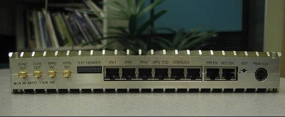
Click to zoom
Application Details
- Equipment Class
- TNB - Licensed Non-Broadcast Station Transmitter
- Date of Grant
- Mar 30, 2005
- Application Purpose
- Original Equipment
- Date of Application
- Mar 30, 2005
- Equipment Note
- iCell CDMA 1X BTS Module - 800 MHz
- Frequency Range
- 869.00000000 - 894.00000000
- Country
- Canada
Documents & Files
Document Text
Text extracted from the exhibit documents filed with the FCC. Open a document above to read the original.
Users Manual
MovingMedia 2000iCell Pico BTS Installation GuidePage1of16 MovingMedia ® 2000 . iCell CDMA2000 1X Pico BTS BASIC INSTALLATION GUIDE RELEASE 4.5 DRAFT 0.1 PART NUMBER NXX0306XXX MovingMedia 2000iCell Pico BTS Installation GuidePage2of16 Copyright © 2004 UTStarcom Incorporated. All rights reserved. Copyright © 2004, UTStarcom, Inc. All rights reserved. No part of this documentation may be reproduced in any form or by any means or used to make any derivative work (such as translation, transformation, or adaptation) without prior written permission from UTStarcom, Inc. UTStarcom, Inc. reserves the right to revise this documentation and to make changes in content from time to time without obligation on the part of UTStarcom, Inc. to provide notification of such revision or change. UTStarcom, Inc. provides this documentation without warranty of any kind, either implied or expressed, including, but not limited to, the implied warranties of merchantability and fitness for a particular purpose. UTStarcom may make improvements or changes in the product(s) and/or the program(s) described in this documentation at any time. UNITED STATES GOVERNMENT LEGENDS: If you are a United States government agency, then this documentation and the software described herein are provided to yousubject to the following: United States Government Legend:All technical data and computer software is commercial in nature and developed solely at private expense. Software is delivered as Commercial Computer Software as defined in DFARS 252.227-7014 (June 1995)or as a commercial item as definedin FAR 2.101(a) and as such is provided with only such rights as are provided in UTStarcom's standard commercial license for the Software. Technical data is provided with limited rights only as provided in DFAR 252.227-7015 (November 1995) or FAR 52.227-14(June 1987), whichever is applicable. You agree not to remove or deface any portion of any legend provided on any licensed program or documentation contained in, or delivered to you in conjunction with, this User Guide. UTStarcom, the UTStarcom logo and MovingMedia 2000 are registeredtrademarks of UTStarcom, Inc. and its subsidiaries. Other brand and product names may be registered trademarks or trademarks of their respective holders. R e g u l a t o r y This device complies with Part 15 of the FCC Rules. Operation of this device is subject to the following two conditions: (1) this device may not cause harmful interference, and (2) this device must accept any interference received including interference that may cause undesired operation. Where appropriate, the use of the equipment is subject to the following conditions: CAUTION! Unauthorized modifications or changes not expressly approved by UTStarcom could void compliance with regulatory rules, and thereby your authority to use this equipment. WARNING (EMI)-United States FCC Information-This equipment has been tested and found to comply with the limits pursuant to Part 15 of the FCC Rules. These limits are designed to provide reasonable protection against harmful interference in an appropriate installation.This equipment generates, uses, and can radiate radio frequency energy and, if not installed and used in accordance with the instructions, may cause harmful interference to radio communication. However, there is no guarantee that interference will not occur in a particular installation.If this equipment does cause harmful interference to radio or television reception, which can be determined by turning the equipment OFF and ON, the user is encouraged to try to correct the interference by one or more of the following measures: –Reorient or relocate the receiving antenna. –Increase the separation between the equipment and receiver. –Connect the equipment into an outlet on a circuit different from that to which the receiver isconnected. –Consult thedealer or an experienced radio/TV technician To comply with Maximum Permissible Exposure (MPE) requirements, the maximum composite output from the antenna cannot exceed 1.26 Watts EIRP and the antenna must be permanently installed in a fixed location that provides at least 13 cm of separation from all persons. MovingMedia 2000iCell Pico BTS Installation GuidePage3of16 1 P R E F A C E 1.1 Objective This document provides installation and configuration instructions for setting up aniCell- CDMA2000 1X system. It covers physical installation,software installation for the various iCell components (sBSC and BTS), configuration, and initial system operation. 1.2 Organization The major sections of this guide are as follows: Table 1-1: Organization Table ChapterTitleDescription Chapter 1PrefaceIntroduction to the Installation Guide. Chapter 2iCell System DescriptionDescribes the System components Chapter 3BTS Physical InstallationProvides mechanical installation and wiring instructions. MovingMedia 2000iCell Pico BTS Installation GuidePage4of16 1.3 Reference Documents The following table summarizes the applicable reference documents. Table 1-2: Reference Documents Ref.TitleNumber 1iCell CDMA2000 1X Alarms and Statistics 2iCell CDMA2000 1X Configuration Guide 1.4 Acronyms and Abbreviations The following table summarizes the acronyms and abbreviations used throughout the document. Table 1-3: Acronyms and Abbreviations 1PPSOne Pulse Per Second AAAAuthentication, Authorization, and Accounting function AbisProtocol interface between sBSC and BTS ASN.1The language used to define the MIB of the NE EMElement Manager GPSGlobal Positioning System HLRHome Location Register sBSCiCell Base Station Controller BTSiCell Base Station Transceiver Subsystem iMBiCell Main Board IOSInter-Operability Standard; A-Interface between sBSC and MSC IPInternet Protocol iPAiCell Power Amplifier MIBManagement Information Base MSMobile Station (phone) MSCMobile Switching Center NENetwork Element or agent NOCNetwork Operations Center OIDObject Identifier OMCOperations & Maintenance Center PAPower Amplifier MovingMedia 2000iCell Pic…
Text truncated - open the document above for the full version.
Cover Letter(s)
UTStarcom Canada 4600 Jacombs Road Richmond, B.C. Canada V6V 3B1 Main : 604.276.0055 Fax: 604.276.0501 www.utstar.com Feb 25, 2005 TCB TÜV America, Inc. 10040 Mesa Rim Road San Diego, CA 92121 Dear Sir or Madam: RE: Authorization of LABTEST to obtain grant forS52P800-1. UTStarcom Canada Company hereby authorizes LabTest Certification Inc, 3133-20800 Westminster Highway, Richmond, British Colombia, V6V 2W3 Canada., Tel#. 604 247 0444to act on our behalf in all matters relating to applications for equipment authorization, including the signing of all documents relating to these matters for proposed FCCID: S52P800-1. We further certify that no party to the applications authorization hereunder is subject to denial of benefits, that includes FCC benefits, pursuant to Section 5301 of the Anti-Drug Abuse Act of 1988, 21 U.S.C. 853 (a). Please direct any questions or comments regarding this request to the undersigned. This agreement expires one year from the above date. Regards, Joe Perrella, P.Eng. Product Manager UTStarcom Canada Company UTStarcom Canada 4600 Jacombs Road Richmond, B.C. Canada V6V 3B1 Main : 604.276.0055 Fax: 604.276.0501 www.utstar.com Feb 25, 2005 TCB TÜV America, Inc. 10040 Mesa Rim Road San Diego, CA 92121 Dear Sir or Madam: RE: Application for Confidentiality pursuant to CFR47 Section 0.459 and 0.457 for certification of Cellular Transceiver, FCC ID: S52P800-1 UTStarcom Canada Company FRN0012744488 requests that all the Schematics, Detailed Circuit Description and Schematics, Parts Lists, Internal Photos and all copies of these documents submitted for FCC ID: S52P800-1 remain confidential due to the proprietary commercial information disclosed therein. These documents detail the exact nature of how our product is designed and would rapidly enable a competitor, without significant capital investment, to replicate our product. Confidentiality for internal photos has been requested since the BTS unit is not sold to the general public and the internal photos would reveal significant design ideas to competitors. The units are sold to licensed wireless operators as sealed units that are professionally installed in various enclosures. Please direct any questions or comments regarding this request to the undersigned. Regards, Joe Perrella, P.Eng. Product Manager UTStarcom Canada Company 604 303 2307
Cover Letter(s)
UTStarcom Canada 4600 Jacombs Road Richmond, B.C. Canada V6V 3B1 Main : 604.276.0055 Fax: 604.276.0501 www.utstar.com March 24, 2005 TCB TÜV America, Inc. 10040 Mesa Rim Road San Diego, CA 92121 Re: Request for Limited Modular approval of Transceiver FCC ID: S52P800-1 We request that the iCell Pico transceiver module be approved as a modular unit, and the unit has the following features which meet the FCC requirement as outlined in its public notice PN27 Aug02. The unit meets the standalone requirements of a module per the following: (1) The unit has its own RF shielding such that the module does not have to rely upon the shielding provided by the device into which it is installed. (2) It has buffered data inputs-Ethernet RJ45 input. (3) The module has its own power supply regulation. (4) Antenna–The module is not sold with antenna. See note below. (5) The module is to be tested in a stand-alone configuration. The only connections required are: DC power, Ethernet RJ45 for control. The antenna is not normally sold with the unit. (6) The nodule will be labeled with its own FCC ID number, and, if the FCC ID is not visible when the module is installed inside another device, then the outside of the device into which the module is installed will display "Contains FCC ID:S52P800-1” It will operate in BandClass 0, licensed Cellular Band. Furthermore,UTSI has no plans to sell the module to an OEM. In other words, UTSI will control the mounting and installation of the module into either a plastic enclosure for wall mounting or into a metal chassis for rack mounting. UTSI will control the installation process such that compliance of the end product is assured. UTStarcom Inc. www.utstar.com The unit is not normally sold with antennas. Licensed Cellular band operators will be responsible for selection of active or passive antennas and ensuring proper installation in commercial buildings. Sincerely, Joe Perrella, P.Eng. Product Manager UTStarcom Canada
External Photos
FCC ID: S52P800-1 Front View of Pico 800 MHz BTS Rear View of Pico 800 MHz BTS Rear and Bottom View of Pico 800 MHz BTS Front and Top View of Pico 800 MHz BTS
ID Label/Location Info
© 2005 UTStarcom Inc. Proprietary -1- Label Information FCC ID: S52P800-1 © 2005 UTStarcom Inc. Proprietary -2- In addition, the Label to be used on the outside of enclosures or rack mount chassis would make reference to: “Contains FCC ID” as required for Modular Transceiver. Following is an exampleof this label: Model No. ____________ Serial No. ____________ FCC ID: S52P800-1 Label location Model No. ____________ Serial No. ____________ Contains FCC ID: S52P800-1 Model No. ____________ Serial No. ____________ FCC ID: S52P800-1
Operational Description
© 2005 UTStarcom Inc. Proprietary and Confidential -1- iCell Pico BTS 800MHz Operational Description Date: Feb. 24, 2005 © 2005 UTStarcom Inc. Proprietary and Confidential -2- iCell Pico BTS 800 MHz Operational Description The iCell BTS CDMA2000 1X core module provides a one CDMA carrier support for one, two or three sector operation. The Pico BTS is limited to 100mWatts per sector. It supports up to three sectors. The Pico BTS module can operate as a standalone Cellular transceiver. It requires a single external Ethernet interface for communication with a BCS server and a connection to anexternal 5.2v DC, 50watt power supply. The Pico BTS module can also be installed into various enclosures which are normally 1U 19” rack mount type. The enclosures contain power supply, fans, and an I/O protection circuit for the RJ45 jacks. There is also a circuit board used to extend the alarm LEDs of the Pico module to the front panel via a ribbon cable. The iCell BTS is designed to comply with the IS-97D standard for base stations for Band Class 0 (Cellular Band) Pico BTS Block Diagram: BTS Module 5.2V DC IP BSC Server Tx/Rx Rx div Sector 1 1 Tx/Rx Rx div Sector 2 1 Tx/Rx Rx div Sector 3 1 AC Adapter 50 Watts Optional GPS Receiver 1 PPS
Test Report
Report No. SC501057-03 Page 1 of 38 Rev.No 1.0 TÜV AMERICA INC 10040 Mesa Rim Road San Diego, CA 92121-2912 Phone 858 678 1400 FAX 858 546 0364 MEASUREMENT AND TECHNICAL REPORT UTSTARCOM CANADA COMPANY 4600 Jacombs Road Richmond, BC V6V 3B1 Canada DATE: 30 March 2005 This Report Concerns: Original Grant: X Class II Change: Equipment Type: iCell BTS with iPA 800 Deferred grant requested per 47 CFR 0.457(d)(1)(ii)? Yes: Defer until: No: X Company Name agrees to notify the Commission by: N/A of the intended date of announcement of the product so that the grant can be issued on that date. Transition Rules Request per 15.37? Yes: No: X* (*) FCC Parts 22, Paragraph(s) 22.917(b) and 22.355 Report Prepared by: TÜV AMERICA, INC 10040 Mesa Rim Road San Diego, CA 92121-2912 Phone: 858 678 1400 Fax: 858 546 0364 Report No. SC501057-03 Page 2 of 38 Rev.No 1.0 TÜV AMERICA INC 10040 Mesa Rim Road San Diego, CA 92121-2912 Phone 858 678 1400 FAX 858 546 0364 TABLE OF CONTENTS Pages 1.0 GENERAL INFORMATION 3 - 16 1.1 Product Description 3 - 14 1.2 Related Submittal Grant 15 1.3 Tested System Details 15 1.4 Test Methodology 15 1.5 Test Facility 16 2.0 SYSTEM TEST CONFIGURATION 17 2.1 Justification 17 2.2 EUT Exercise Software 17 2.3 Special Accessories 17 2.4 Equipment Modifications 17 2.5 Configuration of Test System 17 3.0 RADIATED SPURIOUS EMISSIONS EQUIPMENT/DATA CONDUCTED SPURIOUS EMISSIONS EQUIPMENT/DATA BAND EDGE EQUIPMENT/DATA OUTPUT POWER EQUIPMENT/DATA FREQUENCY STABILITY EQUIPMENT/DATA 18 - 37 4.0 ATTESTATION STATEMENT 38 Report No. SC501057-03 Page 3 of 38 Rev.No 1.0 TÜV AMERICA INC 10040 Mesa Rim Road San Diego, CA 92121-2912 Phone 858 678 1400 FAX 858 546 0364 1.0 GENERAL INFORMATION 1.1 Product Description Report No. SC501057-03 Page 4 of 38 Rev.No 1.0 TÜV AMERICA INC 10040 Mesa Rim Road San Diego, CA 92121-2912 Phone 858 678 1400 FAX 858 546 0364 Report No. SC501057-03 Page 5 of 38 Rev.No 1.0 TÜV AMERICA INC 10040 Mesa Rim Road San Diego, CA 92121-2912 Phone 858 678 1400 FAX 858 546 0364 Report No. SC501057-03 Page 6 of 38 Rev.No 1.0 TÜV AMERICA INC 10040 Mesa Rim Road San Diego, CA 92121-2912 Phone 858 678 1400 FAX 858 546 0364 Report No. SC501057-03 Page 7 of 38 Rev.No 1.0 TÜV AMERICA INC 10040 Mesa Rim Road San Diego, CA 92121-2912 Phone 858 678 1400 FAX 858 546 0364 Report No. SC501057-03 Page 8 of 38 Rev.No 1.0 TÜV AMERICA INC 10040 Mesa Rim Road San Diego, CA 92121-2912 Phone 858 678 1400 FAX 858 546 0364 Report No. SC501057-03 Page 9 of 38 Rev.No 1.0 TÜV AMERICA INC 10040 Mesa Rim Road San Diego, CA 92121-2912 Phone 858 678 1400 FAX 858 546 0364 Report No. SC501057-03 Page 10 of 38 Rev.No 1.0 TÜV AMERICA INC 10040 Mesa Rim Road San Diego, CA 92121-2912 Phone 858 678 1400 FAX 858 546 0364 Report No. SC501057-03 Page 11 of 38 Rev.No 1.0 TÜV AMERICA INC 10040 Mesa Rim Road San Diego, CA 92121-2912 Phone 858 678 1400 FAX 858 546 0364 Report No. SC501057-03 Page 12 of 38 Rev.No 1.0 TÜV AMERICA INC 10040 Mesa Rim Road San Diego, CA 92121-2912 Phone 858 678 1400 FAX 858 546 0364 Report No. SC501057-03 Page 13 of 38 Rev.No 1.0 TÜV AMERICA INC 10040 Mesa Rim Road San Diego, CA 92121-2912 Phone 858 678 1400 FAX 858 546 0364 Report No. SC501057-03 Page 14 of 38 Rev.No 1.0 TÜV AMERICA INC 10040 Mesa Rim Road San Diego, CA 92121-2912 Phone 858 678 1400 FAX 858 546 0364 Report No. SC501057-03 Page 15 of 38 Rev.No 1.0 TÜV AMERICA INC 10040 Mesa Rim Road San Diego, CA 92121-2912 Phone 858 678 1400 FAX 858 546 0364 1.2 Related Submittal Grant None 1.3 Tested System Details The FCC ID’s for all equipment, plus descriptions of all cables used in the tested system are: None 1.4 Test Methodology Purpose of Test: To demonstrate compliance with the following tests. Test Summary Summary of Results Test Description Paragraph Number Low Channel Mid Channel High Channel Pass/Fail Radiated Spurious Emissions 22.917(b) -43.7 dBm -42.7 dBm -36.7 dBm Pass Conducted Spurious Emissions 22.917 -28.3 dBm -28.4 dBm -30.16 dBm Pass Band Edge 22.917 -31.9 dBm -31.5 dBm -31.2 dBm Pass Output Power 22.917 13.6 dBm 14.0 dBm -12.6 dBm Pass Frequency Stability 22.355 -950 Hz +1250 Hz +750 Hz Pass Testing was performed according to the procedures in FCC/ANSI C63.4 and CSA 108.8-M1983. Report No. SC501057-03 Page 16 of 38 Rev.No 1.0 TÜV AMERICA INC 10040 Mesa Rim Road San Diego, CA 92121-2912 Phone 858 678 1400 FAX 858 546 0364 1.5 Test Facility The open area test site and conducted measurement data were tested by: TÜV AMERICA, INC 10040 Mesa Rim Road San Diego, CA 92121-2912 Phone: 858 678 1400 Fax: 858 546 0364 The Test Site Data and performance comply with ANSI C63.4 and are registered with the FCC, 7435 Oakland Mills Road, Columbia Maryland 21046. All Measurement Data is acquired according to the content of FCC Measurement Procedure and ANSI C63.4, unless supplemented with additional requirements as noted in the test report. Report No. SC501057-03 Page 17 of 38 Rev.No 1.0 TÜV AMERICA INC 10040 Mesa Rim Road San Diego, CA 92121-2912 Phone 858 678 1400 FAX 858 546 0364 2.0 SYSTEM TEST CONFIGURATION 2.1 Justification The EUT was initially tested for FCC emissions in the following configuration: See Test Setup Photos Exhibit 2.2 EUT Exercise Software None 2.3 Special Accessories None 2.4 Equipment Modifications None 2.5 Configuration of Test System See Test Setup Photos Exhibit Report No. SC501057-03 Page 18 of 38 Rev.No 1.0 TÜV AMERICA INC 10040 Mesa Rim Road San Diego, CA 92121-2912 Phone 858 678 1400 FAX 858 546 0364 3.0 RADIATED SPURIOUS EMISSIONS EQUIPMENT/DATA CONDUCTED SPURIOUS EMISSIONS EQUIPMENT/DATA BAND EDGE EQUIPMENT/DATA OUTPUT POWER EQUIPMENT/DATA FREQUENCY STABILITY EQUIPMENT/DATA Test Conditions: RADIATED SPURIOUS EMISSIONS: FCC Part 22.917(b) CONDUCTED SPURIOUS EMISSIONS: FCC Part 22.917 BAND EDGE: FCC Part 22.917 OUTPUT POWER: FCC Part 22.917 FREQUENCY STABILITY: FCC Part 22.355 The following measurements were performed at the San Diego Testing Facility: - Test not applicable - Roof (Small Open Area Test S…
Text truncated - open the document above for the full version.
Contact Information
Applicant
Rundeep Chatha(Engineering Manager)
Test Firm
TUV America Inc.Jim Owen
Technical Specifications
| # | Rule Parts | Frequency Range | Power Output | Emission | Tolerance |
|---|---|---|---|---|---|
| 1 | 22H | 869 MHz - 894 MHz | 100.00 mW | 1M25F9W | 2.5000000000 ppm |
Other Applications from Star Solutions International Inc.

S52-7-12-12-00-1
Oct 04, 2023LTE Base Station Band Class 12
Equipment Class
TNB - Licensed Non-Broadcast Station Transmitter
S52-1-10-01-00-1
Nov 20, 2013iCell QUADPAC IX IP-RAN 1900MHz CPU (wo CPU) AC GPS
Equipment Class
PCB - PCS Licensed Transmitter
S52-2-09-01-00-1
Jul 02, 2012iCell COMPAC DO IP-RAN 1900MHz CPU (/wo CPU) DC
Equipment Class
PCB - PCS Licensed Transmitter
S52-1-09-00-00-1
Jun 17, 2012iCell COMPAC 1X IP-RAN 800MHz CPU (/w0 CPU) DC
Equipment Class
TNB - Licensed Non-Broadcast Station Transmitter
S52-2-07-01-00-1
Nov 09, 2010Star Solutions iCell EVDO Indoor Compact BTS 1900MHz
Equipment Class
PCB - PCS Licensed Transmitter