S63BP238DUAL-BAND GSM 850/1900 MHZ MOBILE PHONE
Advanced Wireless Group Limited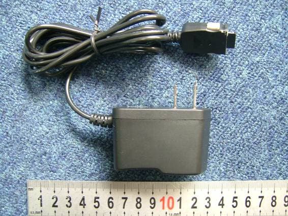
Click to zoom
Application Details
- Equipment Class
- PCE - PCS Licensed Transmitter held to ear
- Date of Grant
- Oct 27, 2005
- Application Purpose
- Original Equipment
- Date of Application
- Oct 27, 2005
- Equipment Note
- DUAL-BAND GSM 850/1900 MHZ MOBILE PHONE
- Frequency Range
- 824.20000000 - 848.80000000
- Country
- Hong Kong
Documents & Files
Document Text
Text extracted from the exhibit documents filed with the FCC. Open a document above to read the original.
Users Manual
BP238 USER MANUAL DISCLAIMER STATEMENT This manual is published by the manufacturer without any warranty. Improvements and changes to this manual necessitated by typographical errors, inaccuracies of current information or improvements to programs and/ or equipment, may be made by the manufacturer at any time and without notice. NOTICE Some services mentioned here are network dependent and may be unsupported by user’s network operator and service provider. Contact your network operator and service provider to check if a service is supported. SAFETY INFORMATION Please read this information for safe and efficient use of this mobile phone and its accessories. Keep phone away from children, dust, excessive moisture and humidity, extreme high or low temperatures, open flames or lit tobacco products. Obey instructions pertaining to phone use especially near medical equipment, in hospitals, in an aircraft, or in areas of potentially explosive atmosphere. Only manufacturer authorized personnel should disassemble the phone. Keep phone away from a car’s airbag. Please use phone with a hands-free device while driving. Please check local regulations for disposal of batteries and electronic products. Use only original batteries and chargers approved for the phone. Failure to comply with safety instructions will void the product warranty. SAR INFORMATION The SAR limit of USA (FCC) is 1.6 W/kg averaged over one gram of tissue. Device types M1211 has also been tested against this SAR limit. The highest SAR value reported under this standard during product certification for use at the ear is 0.645 W/kg and when properly worn on the body is 0.266 W/kg. This device was tested for typical body-worn operations with the back of the handset kept 1.5cm from the body. To maintain compliance with FCC RF exposure requirements, use accessories that maintain a 1.5cm separation distance between the user's body and the back of the handset. The use of belt clips, holsters and similar accessories should not contain metallic components in its assembly. The use of accessories that do not satisfy these requirements may not comply with FCC RF exposure requirements, and should be avoided. ACCESSORIES The BP238 phone support headset, but they are only optional, you can buy from your vendor. 2 TABLE OF CONTENT 1. GETTING STARTED...................................................................................................... 4 2. NAVIGATING THE MENUS........................................................................................... 5 3. QUICK KEYS.................................................................................................................. 5 4. PHONE LAYOUT............................................................................................................ 6 5. ICON DESCRIPTION..................................................................................................... 7 6. MAKE AND RECEIVE CALLS........................................................................................ 8 7. PHONE BOOK................................................................................................................ 8 8. MESSAGE.................................................................................................................... 10 9. CALL HISTORY............................................................................................................ 12 10. SETTINGS.................................................................................................................... 13 11. MULTIMEDIA................................................................................................................ 16 12. FUN & GAMES............................................................................................................. 17 13. USER PROFILES......................................................................................................... 18 14. ORGANIZER................................................................................................................ 19 15. TROUBLE SHOOT....................................................................................................... 20 1. GETTING STARTED NOTE: Insert SIM Card and charge the battery before using phone for the first time. Make sure that the phone is turned off and the charger detached before removing SIM Card, back cover or battery. 1.1 Insert SIM Card Push button at back of phone to remove back cover and battery. Slide SIM Card into place, gold-coloured chip side down. Replace battery and back cover. 1.2 Charge battery Insert charger connector to bottom of the phone. Plug charger into a wall socket. Turn on power. Wait until icon indicates that battery is fully charged. Press on the sides of charger connector to detach it from the phone. NOTE: Charge battery for at least 12 hours prior to first use. It may take several minutes before an icon appears when charging. 1.3 Switching phone on/ off Press ON/OFF key to switch on phone. Key in PIN code (if any), OK. Press and hold ON/OFF key to switch off phone. NOTE: PIN code is provided by your network operator. If you have made a mistake when entering the PIN, press Clear to delete the wrong number, then enter correct PIN. 4 2. NAVIGATING THE MENUS For quick access to menu functions: Press LEFT softkey to select Menu, followed by these number keys. 1 to Phonebook 2 to Messages 3 to Call History 4 to Settings 5 to Multimedia 6 to Fun and Games 7 to User Profiles 8 to Organizer 9 to Shortcuts 3. QUICK KEYS 3.1 Quick keys in idle mode Press sidekeys to adjust Key tone. Press DOWN key to go to Shortcuts menu. Press SEND key to go to Call Logs. Press RIGHT softkey (Name) to go to Phone Book. Press and Hold 0 key to enter + sign. Press and hold ON/OFF to switch phone on/ off. Press UP key to go to Tone Setup. Press and hold 1 to call voice mailbox. 3.2 Quick keys during active call Press SEN…
Text truncated - open the document above for the full version.
Cover Letter(s)
PHOENIX TESTLAB GmbH Product Certification Königswinkel 10 D 32825 Blomberg To Whom It May Concern: Please be advised that Advanced Wireless Group Limited authorizes Morlab to act on our behalf, until otherwise notified, for applications submitted to PHOENIX TESTLAB GmbH (PTL). Thank you for your attention to this matter. 2005-9-22
Cover Letter(s)
PHOENIX TESTLAB GmbH Product Certification Königswinkel 10 D 32825 Blomberg RE: Certification Application FCC ID: S63BP238 Confidentiality Request Pursuant to Section 0.459 of the Commission’s Rule, Advanced Wireless Group Limited hereby requests confidential treatment of information accompanying this Application as outlined below: - Block Diagram - Schematics - Operational Description - Bill Of Materials/Tune-Up-Procedure The above materials contain trade secrets and proprietary information not customarily released to the prublic. The public disclosure of these matters might be harmful to Advanced Wireless Group Limited and provide unjustified benefits to its competitors. Thank you for your attention in this matter. 2005-9-22
External Photos
External Photos 1. Front View of EUT 2. Back View of EUT 3. Back Open 4. all side of the EUT 5. AC/DC adaptor
ID Label/Location Info
Label Label Location
Internal Photos
Internal Photos
RF Exposure Info
No. SAR05-013 Page 3 of 63 Contents 1. GENERAL CONDITIONS 2. ADMINISTRATIVE DATA 2.1. Identification of the Responsible Testing Laboratory 2.2. Identification of the Responsible Testing Location(s) 2.3. Organization Item 2.4. Identification of Applicant 2.5. Identification of Manufacture 3. EQUIPMENT UNDER TEST (EUT) 3.1. Identification of the Equipment under Test 3.2. Identification of all used Test Sample of the Equipment under Test 4. OPERATIONAL CONDITIONS DURING TEST 4.1. Schematic Test Configuration 4.2. SAR Measurement System 5. CHARACTERISTICS OF THE TEST 5.1. Applicable Limit Regulations 5.2. Applicable Measurement Standards 6. LABORATORY ENVIRONMENT 7. TEST RESULTS 7.1. Dielectric Performance 7.2. Summary of Measurement Results 7.3. Conclusion 8. MEASUREMENT UNCERTAINTY 9. MAIN TEST INSTRUMENTS This Test Report consists of the following Annexes: Annex A: Accreditation Certificate Annex B: Test Layout Annex C: Sample Photographs Annex D: Graph Test Results No. SAR05-013 Page 4 of 63 1.GENERAL CONDITIONS 1.1 This report only refers to the item that has undergone the test. 1.2 This report standalone dose not constitute or imply by its own an approval of the product by the certification Bodies or competent Authorities. 1.3 This document is only valid if complete; no partial reproduction can be made without written approval of Shenzhen Electronic Product Quality Testing Center. 1.4 This report cannot be used partially or in full for publicity and/or promotional purposes without previous written approval of Shenzhen Electronic Product Quality Testing Center and the Accreditation Bodies, if it applies. No. SAR05-013 Page 5 of 63 2. Administrative Date 2.1. Identification of the Responsible Testing Laboratory Company Name: ShenZhen Electronic Product Quality Testing Center Department: Testing Department Address: Electronic Testing Building, ShaHe Road, NanShan District, ShenZhen, P. R. China Telephone: +86-0755-26628676 Fax: +86-0755-26627238 Responsible Test Lab Managers: Mr. Wang Keqin 2.2. Identification of the Responsible Testing Location(s) Company Name: ShenZhen Electronic Product Quality Testing Center Address: Electronic Testing Building, ShaHe Road, NanShan District, ShenZhen, P. R. China 2.3. Organization Item S.E.T Report No.: SAR05_013 S.E.T Project Leader: Mr. Li Sixiong S.E.T Responsible for accreditation scope: Mr. Wang Keqin Start of Testing: 2005-9-20 End of Testing: 2005-9-22 2.4. Identification of Applicant Company Name: Advanced Wireless Group Limited Address: Suite 2013, 20F., West Wing Grandtech Centre, 8 On Ping Street, Shaitin, N.T. Hong Kong Contact person: Stephen HO Telephone: (+86)755-2794 2851 Fax: (+86)755-2794 2555 2.5. Identification of Manufacture Company Name: Advanced Wireless Group Limited Address: Blk B, 4/F Qian Jin Road 2, District 75, Liu Tang, Xi Xiang Bao An, ShenZhen. 518102 Contact person: Stephen HO Telephone: (+86)755-2794 2851 Fax: (+86)755-2794 2555 Notes: This data is based on the information by the applicant. No. SAR05-013 Page 6 of 63 3. Equipment Under Test (EUT) 3.1. Identification of the Equipment under Test Brand Name: AWG Type Name: BP238 (production unit) Marking Name: BP238 Test frequency GSM 850MHz PCS 1900MHz Battery type Lithium BP238 Antenna type Build inside Operation mode Call established Modulation mode GSM; NO GPRS; NO BLUETOOTH; General description: Max. Power(EIRP) 0.481w(26.82dBm) 0.324w(25.10dBm) 3.2. Identification of all used Test Sample of the Equipment under Test EUT Code Serial Number Hardware Version Software Version IMEI 18060e01 N.A. BP238REV.0.2 G2CEZZ0208A4 135790246811222 No. SAR05-013 Page 7 of 63 4 OPERATIONAL CONDITIONS DURING TEST 4.1 Schematic Test Configuration During SAR test, EUT is in Traffic Mode (Channel Allocated) at Normal Voltage Condition. A communication link is set up with a System Simulator (SS) by air link, and a call is established. The TCH is allocated to 128, 190 and 251 respectively in the case of GSM 850 MHz, or to 512, 661 and 810 respectively in the case of PCS 1900 MHz. The EUT is commanded to operate at maximum transmitting power. The EUT shall use its internal transmitter. The antenna(s), battery and accessories shall be those specified by the manufacturer. The EUT battery must be fully charged and checked periodically during the test to ascertain uniform power output. If a wireless link is used, the antenna connected to the output of the base station simulator shall be placed at least 50 cm away from the handset. The signal transmitted by the simulator to the antenna feeding point shall be lower than the output power level of the handset by at least 35 dB. 4.2 SAR Measurement System The SAR measurement system being used is the IndexSAR SARA2 system, which consists of a Figure1. SAR Lab Test Measurement Set-up No. SAR05-013 Page 8 of 63 Mitsubishi RV-E2 6-axis robot arm and controller, IndexSAR probe and amplifier and SAM phantom Head Shape. The system is controlled remotely from a PC, which contains the software to control the robot and data acquisition equipment. The software also displays the data obtained from test scans, and determine the averaged SAR values (averaging region 1 gram or 10 gram) for compliance testing. The measurements are done by two scan: first a coarse scan (2-Division) determines the region of the maximum SAR, afterwards the averaged SAR is measured in a second san within the shape of a cube. The measurement time takes about 20 minutes. 4.2.1 Robot system specification The robot is used to articulate the probe to programmed positions inside the phantom head to obtain the SAR readings from the DUT. 4.2.2 Probe and amplifier specification IXP-050 Indexsar isotropic immersible SAR probe The probes are constructed using three orthogonal dipole sensors arranged on an interlocking, triangular No. SAR05-013 Page 9 of 63 prism core. The probes have built-in shielding against static charges and are contained within a PEEK cylindrical enclosure material at the ti…
Text truncated - open the document above for the full version.
Test Report
Report No. FCC05-8030 Page 2 of 52 Table of Contents 1 Test Report Certification ...............................................................................................................5 2 General Information ......................................................................................................................6 2.1 Description of EUT ...............................................................................................................6 2.2 Objective ...............................................................................................................................7 2.3 Test Standards and Results ....................................................................................................7 2.4 List of Equipments Used .......................................................................................................8 2.5 Test Facility ...........................................................................................................................8 2.6 Environmental conditions .....................................................................................................8 3 Conducted Emission Measurement...............................................................................................9 3.1 Limits of Conducted Emission..............................................................................................9 3.2 Test Procedure .......................................................................................................................9 3.3 Test Setup ............................................................................................................................10 3.4 EUT Setup and Operating Conditions.................................................................................10 3.5 Test Results .........................................................................................................................10 4 Radiated Emission Test ...............................................................................................................12 4.1 Limits of Radiated Emission ...............................................................................................12 4.2 Test Procedure .....................................................................................................................12 4.3 Test Setup ............................................................................................................................13 4.4 EUT Setup and Operating Conditions.................................................................................13 4.5 Test Results .........................................................................................................................13 5 Frequencies .................................................................................................................................15 5.1 Frequency Blocks Available for Cellular Service ...............................................................15 5.2 Frequency Blocks Available for Broadband PCS ...............................................................15 5.3 Test Procedure .....................................................................................................................15 5.4 Test Setup ............................................................................................................................16 5.5 EUT Setup and Operating Conditions.................................................................................16 5.6 Test Results .........................................................................................................................17 6 Transmitter Radiated Power (EIRP/ERP) Test ...........................................................................19 Report No. FCC05-8030 Page 3 of 52 6.1 Limits of EIRP/ERP ............................................................................................................19 6.2 Test Procedure .....................................................................................................................19 6.3 Test Setup ............................................................................................................................19 6.4 EUT Setup and Operating Conditions.................................................................................19 6.5 Test Results .........................................................................................................................20 7 Occupied Bandwidth ...................................................................................................................21 7.1 Definition ............................................................................................................................21 7.2 Test Procedure .....................................................................................................................21 7.3 Test Setup ............................................................................................................................21 7.4 EUT Setup and Operating Conditions.................................................................................21 7.5 Test Results .........................................................................................................................22 8 Conducted Spurious Emission Test.............................................................................................24 8.1 Limits of Conducted Spurious Emission.............................................................................24 8.2 Test Procedure .....................................................................................................................24 8.3 Test Setup ............................................................................................................................24 8.4 EUT Setup and Operating Conditions...........................................................................…
Text truncated - open the document above for the full version.
Test Setup Photos
Test Setup Photos 1. CE 2. CSE 3. RE 4. RSE
Contact Information
Applicant
Stephen HO(Sir)
Test Firm
ShenZhen Electronic Product Quality Testing CenterXingsun Lin
Technical Specifications
| # | Rule Parts | Frequency Range | Power Output | Emission | Tolerance |
|---|---|---|---|---|---|
| 2 | 22H | 824.2 MHz - 848.8 MHz | 293.00 mW | 300KGXW | 0.02305 ppm |
Other Applications from Advanced Wireless Group Limited
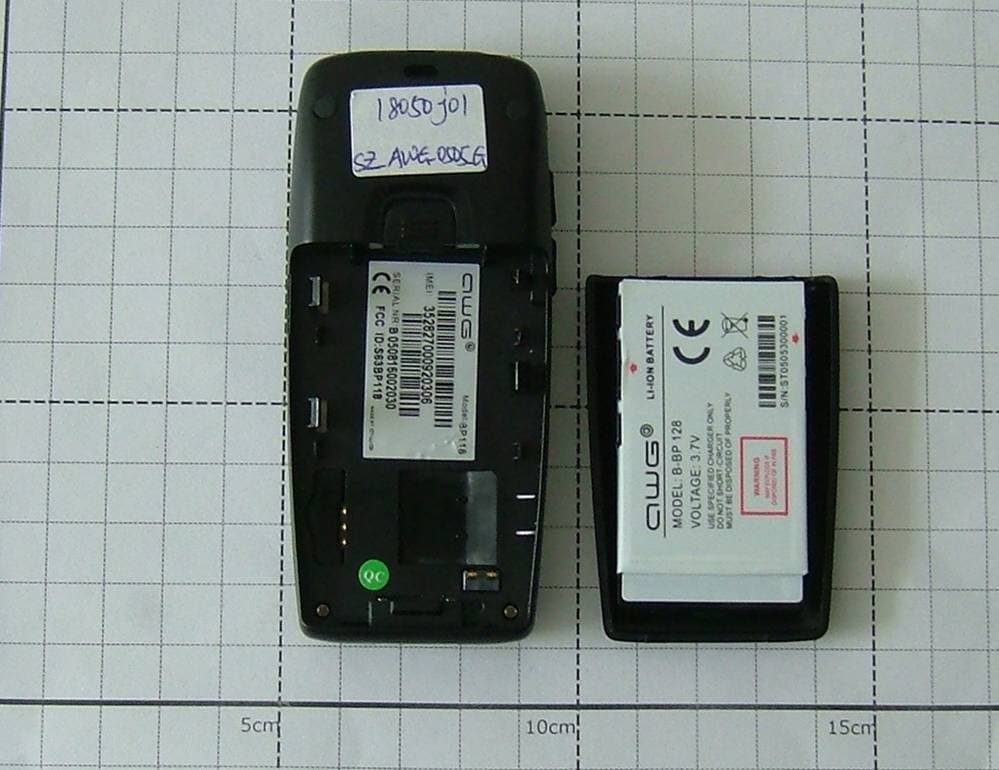
S63BP118
Aug 21, 2005GSM 850/1900 Mobile Phone
Equipment Class
PCE - PCS Licensed Transmitter held to ear