S64MD06Wireless Camera
Moretech Electronics Co., Ltd.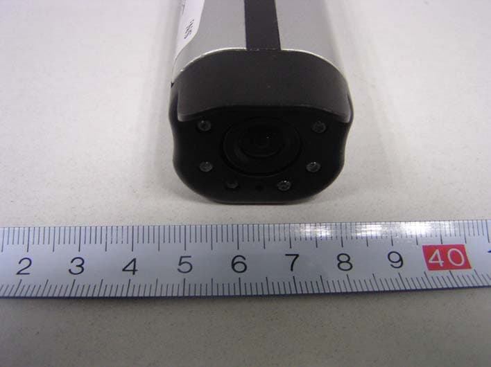
Click to zoom
Application Details
- Equipment Class
- DXX - Part 15 Low Power Communication Device Transmitter
- Date of Grant
- Jan 29, 2006
- Application Purpose
- Original Equipment
- Date of Application
- Jan 29, 2006
- Equipment Note
- Wireless Camera
- Frequency Range
- 2414.00000000 - 2468.00000000
- Country
- China
Documents & Files
Document Text
Text extracted from the exhibit documents filed with the FCC. Open a document above to read the original.
Users Manual
USER’S INSTRUCTIONS 2.4 GHz WIRELESS COLOR CAMERA SYSTEM PORTABLE WIRELESS COLOR CAMERA & RECEIVER MODEL CW3510 WISECOMM LOGO ■ To prevent fire or shock hazard, do not expose this product to rain or moisture. ■ To avoid electrical shock, do not open the case of this product. ■ Operate this product using only the power supply included. ■ Do not overload electrical outlets or extension cords, this can result in fire or electric shock. ■ Keep this product away from the microwave oven, near high voltage and high temperature area, otherwise the battery inside the camera may cause explosion or fire. ■ Do not expose this product in direct sunlight or strong reflected rays. ■ Refer servicing to qualified personnel only. ■ Do not change or modify this product, the warranty terms will be voided. NOTE This equipment has been tested and found to comply with the limits for Class B digital device, pursuant to part 15 of the FCC rules. These limits are designed to provide reasonable protection against harmful interference in a residential installation. This equipment generates, uses and can radiate radio frequency energy and, if not installed and used in accordance with the instructions, may cause harmful interference to radio communications. IMPORTANT SAFETY PRECAUTIONS However, there is no guarantee that interference will not occur in a particular installation. If this equipment does cause harmful interference to radio or television reception, which can be determined by turning the equipment off and on, the user is encouraged to try to correct the interference by one or more of the following measures: ■ Reorient or relocate the receiving antenna. ■ Increase the separation between the equipment and receiver. ■ Connect the equipment into an outlet on a circuit different from that to which the receiver is connected. ■ Consult the dealer or an experienced radio/TV technician for help. HOW TO USE CW3510 FOR OPTIMAL PERFORMANCE 1 CW3510 should be placed on a flat, stable surface to prevent damage to it from falling. 2 For maximum operating range, try to minimize the number of obstacles (TV, other electronics, large steel structures) between the transmitter and the receiver units. 3. Avoid pointing the camera directly into light or extreme sunlight. This will interfere with your ability to obtain a proper image 4. To receive optimum image performance, always make sure lenses are kept clean. 5. This camera is not waterproof. Do not use in wet or high humidity environments, as this can cause damage or electrical shock. WIRLESS CAMERA -------CW3510TX 10 11 3 1 5 4 2 6 7 8 9 12 1.CHARGE LED (RED) Indicates that the built-in battery is being charged. 2.POWER JACK (DC 5V) Plug the 5V adapter (supplied). 3.POWER ON LED (GREEN) Indicates that the power is ON or OFF. 4.ANTENNA Sends audio and video signals. 5.POWER OFF When the switch is at this position, the power is off. 6-9. CHANNEL SELECTION KNOB Must select the same channel on both transmitter and receiver. 10.IR LED Help work at night and dark Place. 11.Universal mounting bracket Make the camera to work at any .direction. 12. Antenna Sends audio and video signals. 1 2 3 4 5 6 7 10 11 12 8 9 1.ANTENNA Receives the audio and video signals. 2. POWER INDICATOR The red LED is lit when the power is on. 3.CHANNEL SELECTION BUTTON Use to find optimal reception. Must select the same channel on both transmitter and receiver. 4.AUTO SWITCHING INDICATOR The yellow LED is lit when in the sequencing mode. 5.CH 1 This light is lit when CH1 has been selected 6.CH 2 This light is lit when CH2 has been selected 7.CH 3 This light is lit when CH3 has been selected. 8.CH 4 This light is lit when CH4 has been selected. 9. BRACKET For the receiver to stand 10.POWER ON/OFF SWITCH Switch for the power On/off. 11.DC IN Plug the 8V adapter (Supplied). 12.AV (AUDIO/VIDEO) OUTPUT JACK Connect the supplied A/V cable to the jack. Plug the yellow colored RCA to the VIDEO IN on the monitor/TV and the white colored RCA to the AUDIO IN respectively. WIRELESS RECEIVER---CW3510RX INSTALLATION Change the picture above from RX to TX(camera) 1. Connect the supplied adaptor (DC 5V 700mA) to the DC IN jack on the rear of the camera and plug it into AC power outlet. The red LED (power indicator light) on the back of the camera will be lit and the battery (inside the camera) will be charging (green LED). 2. Charge the battery first for 2 hours prior to use. 3. Select the channel you wish to view. SEL CH1 CH2 CH3 CH4 POWER INDICATOR AUTO SWITCHING INDICATOR WIRELESS CAMERA---CW3510TX 1. Connect the supplied AC adaptor (DC 8V 200 mA to the DC IN jack of the receiver and plug it into AC outlet. 2. Connect the supplied A/V cable to the jack. Plug the yellow colored RCA to the VIDEO IN on the monitor/TV and the white colored RCA to the AUDIO IN respectively. 3. Turn on the power switch. 4. Press the SEL button to select the same channel as the camera. DC IN AV O U T POWER ON/OFF ANTENNA WIRELESS RECEIVER---CW3510RX OPERATION ■ MANUAL MODE Select the same channel with the SEL button on receiver as the channel of camera. ■ AUTOMATIC MODE Press SEL button on the receiver after CH 4 indicator is lit. It will be in the sequencing mode. Please check the explanation. ■ OPERATION WITH TV /MONITOR 1. If your color TV/MONITOR has A/V jacks, connect the supplied A/V cable to TV’s A/V jacks and to the A/V jack on the receiver. Be sure to connect the white connector of the A/V cable to the AUDIO IN jack and the yellow connector of the A/V cable to the VIDEO IN jack on the TV or MONITOR. 2. Plug the provided AC adapter (DC 8V 200mA) into the DC jack on the receiver and the other end into AC outlet. Make sure the POWER switch is in the OFF position beforehand. 3.Locate and orient the receiver to get optimal performance. 4.Be sure the TV/monitor and the receiver are turned on. REDRAW THE PICTURE TV/MONITOR RECEIVER ■ OPERATION WITH TV/MONITOR AND VCR 1.Connect the provided A/V (audio/video) cable to the A/V jack on the re…
Text truncated - open the document above for the full version.
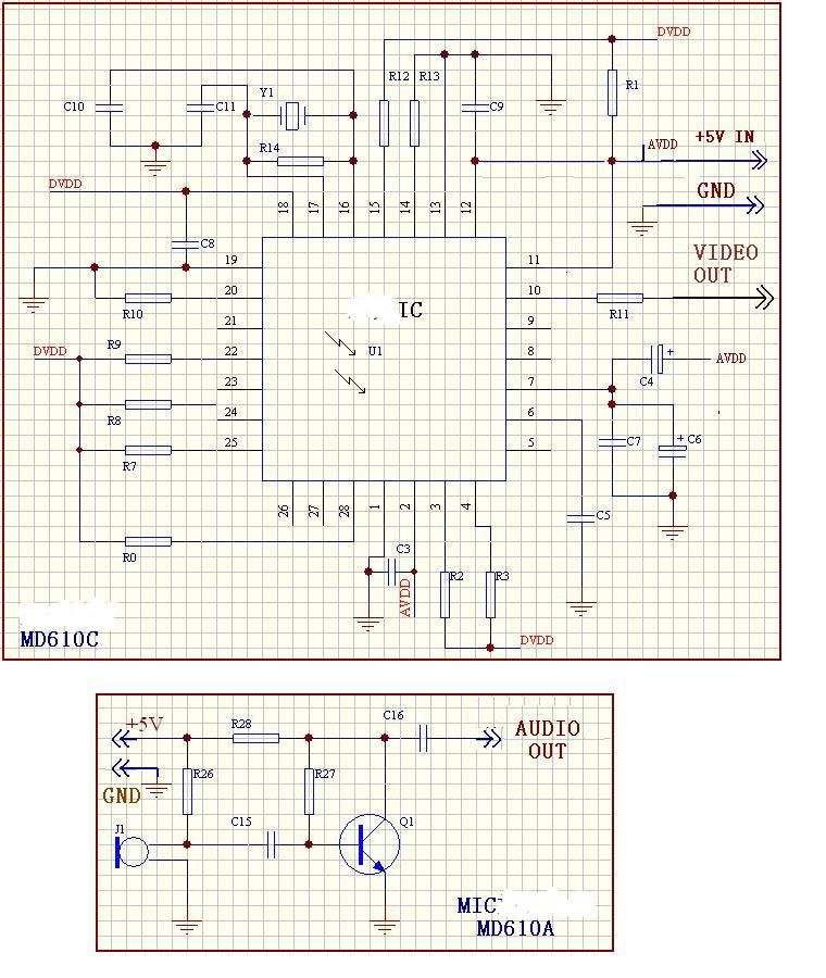
Block Diagram
Block Diagram ANT Video Audio Power DC 5V CMOS Camera VCO 2414~2468 MHz Modulator RF Power AMP Microphone 6.0MHz Modulator Audio AMP 3.6 - 5 V Regulatoer 2.4-2.5G Band-Pass Filters
External Photos
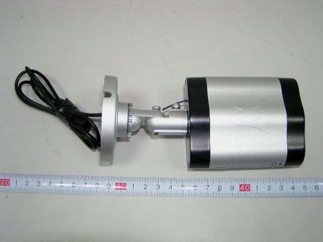
External Photos EUT- View EUT-Front View EUT-Back View
ID Label/Location Info
ID Label Label FCC ID: S64MD06
ID Label/Location Info
ID Label/Location Label Location Information Specifications: Text is Black or white in color and is left justified. Labels are printed in indelible ink on permanent adhesive backing or silk-screened onto the EUT or shall be affixed at a conspicuous location on the EUT. Label Location
Internal Photos
Internal Photos EUT-Inside View EUT- Main PCB Front EUT- Main PCB Back EUT- RF PCB Front View EUT- RF PCB Back View EUT- LED PCB Front View EUT- LED PCB Back View EUT- Camera Lens PCB View EUT- Battery Front View EUT- Battery Back View
Operational Description
Operational Description CW3510 wireless transmitter module intended for in 2414~2468MHz wireless A/V signal Sender and Receive set as RF output modulator, which converts the FM video and audio signal into the RF signal for TV or monitor. This device has a outside antenna. You can fixed the device on a table or wall by screwed the mounting base. To fix the device, please follow the installation. And please make sure the supervision and monitor are set the same band before in use.
Operational Description
Specification for CW3510 wireless camera * Transistors frequency CH1:2414MHZ ,CH2:2432MHZ ,CH3:2450MHZ ,CH4: 2468MHZ * Audio modulate: 6.0MHZ *Modulation: FM *Turn up procedure: phase locking loop *Microphone Frequency range: 20~20,000Hz * Power supply: DC 5V/700mA * Video System: PAL/NTSC * Output RF Power: 50m * Video Level: 1Vp-p * Transmitter Antenna: 30mm * Indoor/Outdoor: Indoor Only * Audio Input Impedance :0.6k * Video Input Impedance:0.075K
Test Report
Note: The test report is specially limited to the above company and this particular sample only. It may not be duplicated without prior written consent of Bay Area Compliance Lab Corp. (ShenZhen). This report must not be used by the client to claim product certification, approval, or endorsement by NVLAP, NIST or any agency of the US Government. FCC PART 15.249 EMI MEASUREMENT AND TEST REPORT For Moretech Electronics Co.,Ltd. 6/F, Budg.9, Shuang Long Shan Industrial District Meixi, Zhuhai FCC ID: S64MD06 January 23, 2006 This Report Concerns: Original Report Equipment Type: Wireless Camera Test Engineer: Kamn Hu Report No.: RSZ06011327 Test Date: January 17-18, 2006 Reviewed By: Chris Zeng Prepared By: Bay Area Compliance Lab Corp. (ShenZhen) 6/F, the 3rd Phase of WanLi Industrial Building, ShiHua Road, FuTian Free Trade Zone, ShenZhen, Guangdong 518038, P.R.China Tel: +86-755-33320018 Fax: +86-755-33320008 Moretech Electronics Co.,Ltd. FCC ID: S64MD06 Report # RSZ06011327 Page 2 of 27 FCC PART 15.249 Report TABLE OF CONTENTS GENERAL INFORMATION.......................................................................................................................................3 PRODUCT DESCRIPTION FOR EQUIPMENT UNDER TEST (EUT) ....................................................................................3 OBJECTIVE...................................................................................................................................................................3 RELATED SUBMITTAL(S)/GRANT(S).............................................................................................................................3 TEST METHODOLOGY..................................................................................................................................................3 TEST FACILITY.............................................................................................................................................................3 EXTERNAL I/O CABLE.................................................................................................................................................4 SYSTEM TEST CONFIGURATION ..........................................................................................................................5 JUSTIFICATION.............................................................................................................................................................5 EUT EXERCISE SOFTWARE..........................................................................................................................................5 SPECIAL ACCESSORIES.................................................................................................................................................5 BLOCK DIAGRAM/SCHEMATICS...................................................................................................................................5 E QUIPMENT M ODIFICATIONS .......................................................................................................................................5 C ONFIGURATION OF T EST S ETUP .................................................................................................................................6 B LOCK D IAGRAM OF T EST S ETUP ................................................................................................................................6 SUMMARY OF TEST RESULTS...............................................................................................................................7 §15.203 - ANTENNA APPLICATION ........................................................................................................................8 STANDARD APPLICABLE..............................................................................................................................................8 §15.207 - CONDUCTED EMISSION ..........................................................................................................................9 MEASUREMENT UNCERTAINTY....................................................................................................................................9 EUT SETUP..................................................................................................................................................................9 EMI TEST RECEIVER SETUP......................................................................................................................................10 TEST EQUIPMENT LIST AND DETAILS.........................................................................................................................10 TEST PROCEDURE......................................................................................................................................................10 TEST RESULTS SUMMARY..........................................................................................................................................10 TEST DATA................................................................................................................................................................11 PLOT(S) OF TEST DATA..............................................................................................................................................13 §15.205 §15.209(A) §15.249(A) - RADIATED EMISSION ......................................................................................20 MEASUREMENT UNCERTAINTY..................................................................................................................................20 EUT SETUP................................................................................................................................................................20 EMI TEST RECEIVER SETUP.........................................................................................................................…
Text truncated - open the document above for the full version.
Test Setup Photos
Test Setup Photos Conducted Emission-Front View Conducted Emission-Side View Radiated Emissions-Front View (below 1GHz) Radiated Emissions-Rear View (below 1GHz) Radiated Emissions-Front View (above 1GHz) Radiated Emissions-Rear View (above 1GHz)
Contact Information
Applicant
Helen Chen(Manager)
Test Firm
Bay Area Compliance Laboratory Corp. (Shenzhen)John Chan
Technical Specifications
| # | Rule Parts | Frequency Range | Power Output |
|---|---|---|---|
| 1 | 15C | 2.41 GHz - 2.47 GHz | - |
Other Applications from Moretech Electronics Co., Ltd.
S64MD08
Mar 15, 2007Wireless Camera
Equipment Class
DXX - Part 15 Low Power Communication Device Transmitter
S64WW7700
Apr 13, 20052.4GHz WIRELESS CAMERA SYSTEM
Equipment Class
DXX - Part 15 Low Power Communication Device Transmitter