S64MD08Wireless Camera
Moretech Electronics Co., Ltd.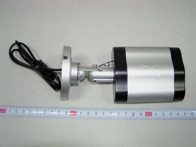
Click to zoom
Application Details
- Equipment Class
- DXX - Part 15 Low Power Communication Device Transmitter
- Date of Grant
- Mar 15, 2007
- Application Purpose
- Original Equipment
- Date of Application
- Mar 15, 2007
- Equipment Note
- Wireless Camera
- Frequency Range
- 2414.00000000 - 2468.00000000
- Country
- China
Documents & Files
Document Text
Text extracted from the exhibit documents filed with the FCC. Open a document above to read the original.
Users Manual
MODEL CW5700 PORTABLE WIRELESS COLOR CAMERA & RECEIVER WITH BUILT-IN USB DVR WIRELESS CAMERA USER'S INSTRUCTIONS Turn your PC to Digital Video Recorder. KEY FEDATURES Plug & play Easy Installation Fast USB2.0 Data Transfer 30F/Sec Recorking Speed Uses Aduanced Mpeg 4 Compression Remote Monitoring via Internet Built-in Motion Detection Scheduled and Timed Recording Remotely record and store images on Your computer hard drive FEATURES: Transmits video and audio signals from the camera to your TV or Monitor Built-in-rechargeable Lithium battery 4channel frequency available to avoid interference Built-in microphone W/IR LEDs for night vision (SEE in total darkness) RANGE UP TO 400ft SPECIFICATIONS Receiver Receiving Frequency ①2414MHZ ②2432MHZ ③2450MHZ ④2468MHZ Demodulation FM Antenna 50ohm SMA Video Output Level 1vpp@75Ω,S/N>38db Audio Output Level 1vpp@600Ω Power Supply +8V DC Current consumption 250mA Operating Temperature –10°C-50°C/14°F-122°F Storage Temperature -40°C-85°C/ -40F°F -185°F O Operating Humidity 85%RH Dimensions (W*L*H) 5”*4.4”*1” Weight 178g Camera Imaging Sensor 1/3-inch Horizontal Resolution 380TV Line View Angle 62° Minimum Illumination 1.5Lux/F1.5 Gain control Automatic Frequency ①2414MHZ ②2432MHZ ③2450MHZ ④2468MHZ Modulation FM Bandwidth 18MHZ Power Supply +12V DC Current consumption 250mA Operating Temperature –10°C 50°C/14°f-122°f Storage temperature –40°C-85°C/-40°f-185°f Operating humidity 85%RH Dimensions(W*L*H) 6.4”*3.2”*1.5” Weight 595g Range 400ftin line of sight Night Vision Range 40ft (Min) Peace of Mind This easy-to-use Wireless Camera System Allows you to check on entry ways, Playrooms, etc from the comfort of another room. Safety With the added benefit of the infrared LEDs on the camera, you can watch the entry ways day or night from the safety and comfort of your home. Convenience This Wireless Video Camera system is easy to use and portable. You can take the system with you throughout your home without worrying about tangled-up wires. Outdoor/lndoor color camera Small enough to be placed anywhere Infrared Lights enable camera to see in total darkness IMPORTANT SAFETY PRECAUTIONS ·To prevent fire of shock hazard, do not expose this product to rain or moisture. ·To avoid electrical shock, do not open the case of this product. ·Operate this product using only the power supply included. ·Do not overload electrical outlets or extension cords, this can result in fire or electric shock. ·Keep this product away from the microwave oven, near high voltage and high temperature area, otherwise the battery inside the camera may cause explosion or fire. ·Do not expose this product in direct sunlight or strong reflected rays. ·Refer servicing to qualified personnel only. ·Do not change or modify this product, the warranty terms will be voided. HOW TO USE CW5700 FOR OPTIMAL PERFORMANCE 1.CW5700 should be placed on a flat, stable surface to prevent damage to it from falling. 2.For maximum operation range, try to minimize the number of obstacles(TV, Other electronics, large steel structures) between the transmitter and the receiver units. 3.Avoid pointing the camera directly into light or extreme sunlight, This will interfere with your ability to obtain a proper image 4.To receive optimum image performance, always make sure lenses are kept clean. 5.This camera is not waterproof. Do not use in wet or high humidity environments, as this can cause damage or electrical shock. WIRLESS CAMERA-CW5700TX 3.CHANNEL SELECTION KNOB Must select the same channel on both transmitter and receiver. 4. IR LED Automatically turns on at night to view objects in darkness. 5. Mounting bracket Install the mounting bracket where you want to. 1. POWER JACK Plug the supplied DC 15V 250mA adapter 2. ANTENNA Sends audio and video signals. WIRELESS RECEIVER-CW5700RX 1. ANTENNA Receives the audio and video signals. 2. USB indicator The red LED is lit when the receiver is connected to computer with USB cable. 3. POWER INDICATOR The red LED is lit when the power is on. 4. AUTO SWITCHING INDICATOR The yellow LED is lit when in the sequencing mode. 5. CH 1 The light is lit when CH1 has been selected. 6. CH 2 This light is lit when CH2 has been selected 7. CH3 This light is lit when CH3 has been selected. 8. CH4 This light is lit when CH4 has been selected. 9. MOUNTING BRACKET For the receiver to stand. 10. POWER ON/OFF SWITCH Switch for the power On/Off. 11. DC IN Plug the 8V adapter (Supplied) 12. AV (AUDIO/VIDEO) OUTPUTJACK Connect the supplied A/V cable to the jack. Plug the yellow. colored RCA to the VIDEO IN on the monitor / TV and the white colored RCA to the AUDIO IN respectively. 13. CHANNEL SELECTION BUTTON Use to find optimal reception. Must select the same channel on both transmitter and receiver. 14. Connector to USB Transfer signal to USB connector. INSTALLATION WIRELESSS CAMERA-CW5700TX 1.Connect the supplied adaptor(DC 15V 250mA )to the DC IN jack of the power cable on the rear of the camera and plug it into AC power outlet. The red LED (power indicator light)on the back of the camera will be lit. 2.Select the channel you wish to view. WIRELESS RECEIVER-CW5700RX 1. Connect the supplied AC adaptor (DC 8V 250mA) to the DC IN jack of the receiver and plug it into AC outlet. 2. Connect the supplied A/V cable to the jack. Plug the yellow colored RCA to the VIDIO IN on the monitor/TV and the white colored RCA to the AUDIO IN respectively. 3. Turn on the power switch. 4. Press the channel selection button to select the same channel as the camera. 5. Refer to the software in the disc included for USB function. OPERATION ·MANUAL MODE Select the same channel with the channel selection button on receiver as the channel of camera. A green LED's light indicates the channel you selected. ·AUTOMATIC SEQUENCING MODE Press channel selection button on the receiver after CH 4 indicator is lit. it will be in the sequencing mode. ·OPERATION WITH TV/MONITOR 1. If your color TV/MONITOR has A/V jacks, connect the…
Text truncated - open the document above for the full version.
Block Diagram
Block Diagram 2414-2468MHz
External Photos
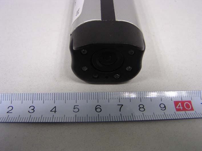
EXHIBIT B - EUT EXTERNAL PHOTOGRAPHS EUT with Accessory View EUT – Front View EUT – Rear View EUT – Top View
ID Label/Location Info
EXHIBIT A - FCC ID LABELING AND LOCATION Proposed FCC ID Labeling Proposed FCC ID Location Label Location FCC ID: S64MD08 This device complies with Part 15 of the FCC Rules. Operation is subject to the following two conditions: (1) this device may not cause harmful interference, and (2) this device must accept any interference received, including interference that may cause undesired operation.
Internal Photos
EXHIBIT C - EUT INTERNAL PHOTOGRAPHS EUT – PCB 1 Top View EUT – PCB 1 Unshielded Top View EUT – PCB 1 Bottom View EUT – PCB 2 Top View EUT – PCB 2 Bottom View
Operational Description
TX operating principle CMOS shoots the video signal resembling machine waiting for the wave filter being composed of via R6 R7 C1 C8, the wave filtering queen enters MIX after R9, another group an audible signal accompanying sound by that C22 R20 entering Q3 Q4 (VCO1) and producing 6 MHZ subsidiary carrier wave, C2 waits for composition, generates 2 from C10 R10 entrance MIX VCO2 from Q1 D1. 4 G high frequency signal, launch by that Gao Fang Q2 enlarges the day after tomorrow from air wire to the outside, while working, another a group of signal controls local oscillator frequency from MCU the I/ O signal that (IC1) produces delivers to PPL (IC2), Let the X-mitter stability job, MCU have four set of frequency choosing from the switch thereby.
Schematics
桌面发射器
Test Report
Note: This test report is for the customer shown above and their specific product only. It may not be duplicated or used in part without prior written consent from Bay Area Compliance Laboratory Corp. (Shenzhen). This report must not be used by the customer to claim product certification, approval, or endorsement by NVLAP, NIST or any agency of the Federal Government. FCC PART 15.249 EMI MEASUREMENT AND TEST REPORT For Moretech Electronics Co., Ltd. 6/F, Bldg. 9, Shuang Long Shan Industrial District, Meixi, Zhuhai, Guangdong, China FCC ID: S64MD08 This Report Concerns: Original Report Equipment Type: Wireless Camera Test Engineer: Deny Xiong Report No.: RSZ07022702 Test Date: 2007-03-02 to 2007-03-06 Report Date: 2007-03-07 Reviewed By: EMC Manager: Boni Baniqued Prepared By: Bay Area Compliance Laboratory Corp. (Shenzhen) 6/F, the 3rd Phase of WanLi Industrial Building, ShiHua Road, FuTian Free Trade Zone Shenzhen, Guangdong, China Tel: +86-755-33320018 Fax: +86-755-33320008 Moretech Electronics Co., Ltd. FCC ID: S64MD08 Report # RSZ07022702 Page 2 of 25 FCC PART 15.249 Report TABLE OF CONTENTS GENERAL INFORMATION.......................................................................................................................................3 PRODUCT DESCRIPTION FOR EQUIPMENT UNDER TEST (EUT) .....................................................................................3 OBJECTIVE...................................................................................................................................................................3 RELATED SUBMITTAL(S)/GRANT(S).............................................................................................................................3 TEST METHODOLOGY..................................................................................................................................................3 TEST FACILITY.............................................................................................................................................................3 EXTERNAL I/O CABLE..................................................................................................................................................4 SYSTEM TEST CONFIGURATION ..........................................................................................................................5 JUSTIFICATION.............................................................................................................................................................5 EQUIPMENT MODIFICATIONS.......................................................................................................................................5 CONFIGURATION OF TEST SETUP.................................................................................................................................6 BLOCK DIAGRAM OF TEST SETUP................................................................................................................................6 SUMMARY OF TEST RESULTS ...............................................................................................................................7 §15.203 - ANTENNA REQUIREMENT......................................................................................................................8 STANDARD APPLICABLE..............................................................................................................................................8 ANTENNA CONNECTOR CONSTRUCTION......................................................................................................................8 §15.207 - CONDUCTED EMISSIONS ........................................................................................................................9 MEASUREMENT UNCERTAINTY....................................................................................................................................9 EUT SETUP..................................................................................................................................................................9 EMI TEST RECEIVER SETUP.......................................................................................................................................10 TEST EQUIPMENT LIST AND DETAILS.........................................................................................................................10 TEST PROCEDURE......................................................................................................................................................10 TEST RESULTS SUMMARY..........................................................................................................................................10 TEST DATA................................................................................................................................................................11 PLOT(S) OF TEST DATA..............................................................................................................................................14 §15.205 §15.209(A) §15.249(A) §15.249(C) - RADIATED EMISSIONS ................................................................20 MEASUREMENT UNCERTAINTY..................................................................................................................................20 EUT SETUP................................................................................................................................................................20 EMI TEST RECEIVER SETUP.......................................................................................................................................21 TEST EQUIPMENT LIST AND DETAILS.........................................................................................................................21 TEST PROCEDURE...................................................................................................…
Text truncated - open the document above for the full version.
Test Setup Photos
EXHIBIT D - TEST SETUP PHOTOGRAPHS Conducted Emissions - Front View Conducted Emissions - Rear View Radiated Emissions - Front View (30 MHz-1 GHz) Radiated Emissions - Rear View (30 MHz-1 GHz) Radiated Emissions - Front View (Above 1 GHz) Radiated Emissions - Rear View (Above 1 GHz)
Contact Information
Applicant
Helen Chen(Manager)
Test Firm
Bay Area Compliance Laboratory Corp. (Shenzhen)John Chan
Technical Specifications
| # | Rule Parts | Frequency Range | Power Output |
|---|---|---|---|
| 1 | 15C | 2.41 GHz - 2.47 GHz | - |
Other Applications from Moretech Electronics Co., Ltd.
S64MD06
Jan 29, 2006Wireless Camera
Equipment Class
DXX - Part 15 Low Power Communication Device Transmitter
S64WW7700
Apr 13, 20052.4GHz WIRELESS CAMERA SYSTEM
Equipment Class
DXX - Part 15 Low Power Communication Device Transmitter