S6MSMBT1Bluetooth module
Sokkia Topcon Co., Ltd.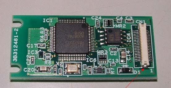
Click to zoom
Application Details
- Equipment Class
- DSS - Part 15 Spread Spectrum Transmitter
- Date of Grant
- Sep 25, 2006
- Application Purpose
- Original Equipment
- Date of Application
- Sep 25, 2006
- Equipment Note
- Bluetooth module
- Frequency Range
- 2402.00000000 - 2480.00000000
- Company
- Sokkia Topcon Co., Ltd.
- Country
- Japan
Documents & Files
Document Text
Text extracted from the exhibit documents filed with the FCC. Open a document above to read the original.
Users Manual
SURVEYING INSTRUMENTS Class 3R Laser Product Class 1 LED Product OPERATOR'S MANUAL Series SRX SRX1 SRX2 SRX3 SRX5 Total Station Li-ion S Li-ion This is the mark of the Japan Surveying Instruments Manufacturers Association. Class 3R Laser Product Class 1 LED Product SURVEYING INSTRUMENTS Series SRX SRX1 SRX2 SRX3 SRX5 Total Station OPERATOR’S MANUAL • Thank you for selecting the SRX1/2/3/5. • Before using the instrument, please read this operator’s manual carefully. • Verify that all equipment is included. "26. STANDARD EQUIPMENT" • SRX has a function to output data saved in Program mode (SDR) to a connected host computer. Command operations from a host computer can also be performed. For details, refer to “Interfacing with the SOKKIA SDR Electronic Field Book” and “Command Explanations” manuals and ask your Sokkia agent. • The specifications and general appearance of the instrument may be altered at any time and may differ from those appearing in brochures and this manual. • Some of the diagrams shown in this manual may be simplified for easier understanding. ii HOW TO READ THIS MANUAL Regarding other manuals •Manuals 2, 3, and 4 below are electronic manuals provided on a CD-ROM in PDF format ( ). •The SRX comes equipped with 4 manuals for operation information: 1. SRX Operator’s Manual (this manual): Explains basic operation and functions of the SRX. 2. Series SRX SDR Software Reference Manual : Explains advanced measurement operations using the SRX in Program mode (SDR), and methods for managing measured data. 3. SFX Dial-Up Program Explanations : Explains how to send and receive data using the SFX function 4. Series SRX Quick Manual : Simplified explanations of operations such as Auto-Tracking to allow users to get started straight away. Symbols The following conventions are used in this manual. [Softkey] etc.: Indicates softkeys on the display and window dialog buttons. {Key} etc.: Indicates keys on the operation panel. <Setting out> etc.: Indicates screen titles. Notes regarding manual style • Except where stated, “SRX” means “SRX1/SRX2/SRX3/SRX5” in this manual. • Screens and illustrations appearing in this manual are of SRX3. • Location of softkeys in screens used in procedures is based on the factory setting. It is possible to change the allocation of softkeys. Softkey allocation: "21.6 Allocating Key Functions" • Kodak Gray Card: KODAK is a registered trademark of Eastman Kodak Company. : Indicates precautions and important items which should be read before operations. :Indicates the chapter title to refer to for additional information. :Indicates supplementary explanation. :Indicates an explanation for a particular term or operation. iii SURVEYING INSTRUMENTS • Bluetooth: Bluetooth ® is a registered trademark of Bluetooth SIG, Inc. •Windows CE ® is a registered trademark of Microsoft Corporation. • All other company and product names featured in this manual are registered trademarks of each respective organization. Operation procedure • Learn basic operations in "4. PRODUCT OUTLINE" and "5. BASIC OPERATION" before you read each measurement procedure. An overview of the available SRX functions is given in "4.1 Functions". For selecting options and inputting figures, see "5.1 Basic Key Operation". • For Auto Tracking measurement, read this manual in conjunction with the On-demand Remote Control System Manual. • Measurement procedures are based on continuous measurement. Some information about procedures when other measurement options are selected can be found in “Note” ( ). iv CONTENTS 1. PRECAUTIONS FOR SAFE OPERATION ................. 1 2. PRECAUTIONS........................................................... 4 3. LASER SAFETY INFORMATION ............................... 6 4. PRODUCT OUTLINE ................................................. 8 4.1Functions ........................................................................... 8 4.2Parts of the Instrument .................................................... 10 4.3Mode Configuration ......................................................... 15 4.4Bluetooth Wireless Technology ....................................... 16 5. BASIC OPERATION ................................................. 18 5.1Basic Key Operation ....................................................... 18 5.2Display Functions ............................................................ 23 5.3Inputting Characters using SIP Code (Input Panel) ........ 29 5.4SETTINGS Mode ............................................................ 30 6. USING THE CF CARD SLOT ................................... 32 6.1Inserting/Removing the CF Card ..................................... 32 7. USING THE BATTERY ............................................ 34 8. CONNECTING TO EXTERNAL DEVICES ............... 36 8.1Wireless Communication using Bluetooth Technology ... 36 8.2Communication between the SRX and Companion Device ......................................................................................... 40 8.3Connection via RS-232C cable ....................................... 42 8.4Connecting to USB devices ............................................ 42 9. SETTING UP THE INSTRUMENT ........................... 44 9.1Centering ......................................................................... 44 9.2Levelling .......................................................................... 45 10. POWER ON/OFF ..................................................... 48 10.1 Resolving Software Issues .............................................. 49 10.2 Configuring the Touch Panel ........................................... 49 10.3 Powering the SRX ON/OFF from an External Instrument 50 11. TARGET SIGHTING ................................................. 51 11.1 Auto Pointing Settings ..................................................... 52 11.2 Auto-Pointing Function for Target Sighting ..................... 54 11.3 Manually Sighting the Target ...........................…
Text truncated - open the document above for the full version.
External Photos
External Photo (SM-BT1) I/F Connector Dipole Antenna SMA Connector Bluetooth Module
ID Label/Location Info
Label for End Product Label for BT module
ID Label/Location Info
Pasitng posision of a label 20 43
Internal Photos
WML-C30 Photos. Top view. Module without antenna. Bottom view. Module without antenna Photo without shielded case. Module without antenna
RF Exposure Info
Applicant: SOKKIA CO., LTD. Type of Equipment : Bluetooth Module Model No. : SM-BT1 FCC ID: S6MSMBT1 SOKKIA CO., LTD. declares that Model : Bluetooth Module complies with FCC radiation exposure requirement specified in the FCC Rules 2.1091. The “SM-BT1“ has 10.33 mW of conducted Peak Output power and 16.37 mW of EIRP. The Following calculation is the reference data for 20cm distance for mobile use. RF Exposure Calculations: The following information provides the minimum separation distance for the highest gain antenna provided with the “SM-BT1“ as calculated from FCC OET Bulletin 65 Appendix A, Table (B) Limits for General Population / Uncontrolled Exposure. This calculation is based on the highest EIRP possible from the system, considering maximum power and antenna gain, and considering a 1.0mW/cm^2 uncontrolled exposure limit. The Friis formula used was: S = (P * G) / (4 * π * r 2 ) Where P = 10.33 mW (Maximum peak output power) G = 1.58 Numerical Antenna gain; equal 2.00 dBi r =20.0 cm For: SM-BT1S = 0.00326 mW/cm 2 RF Exposure for Mobile use No. : 26LE0147-YK-A
Test Report
FCC ID : S6MSMBT1 Test report No. : 26LE0147-YK-A Page : 1 of 82 Issued date : August 29, 2006 Revised date : September 1, 2006 UL Apex Co., Ltd. YAMAKITA EMC LAB. 907 Kawanishi, Yamakita-machi, Ashigarakami-gun, Kanagawa-ken, 258-0124 JAPAN Telephone: +81 465 77 1011 Facsimile: +81 465 77 2112 MF060b (14.06.06) EMI TEST REPORT Test Report No. : 26LE0147-YK-A Applicant : SOKKIA CO., LTD. Type of Equipment : Bluetooth Module Model No. : SM-BT1 FCC ID : S6MSMBT1 Test Standard : FCC Part15 Subpart C, Section 15.207, Section 15.209, Section 15.247: 2006 Test Result : Complied 1. This test report shall not be reproduced except in full, without the written approval of UL Apex Co., Ltd. 2. The results in this report apply only to the sample tested. 3. This equipment is in compliance with the above regulation. 4. The test results in this test report are traceable to the national or international standards. Date of test: July 21, 26, 27, 28, 31 and August 4, 21 and September 1, 2006 Tested by: Tatsuya Arai & Fumiaki Matsuo Tested by: Toyokazu Imamura & Akira Sato Approved by: Osamu Watatani Site Manager of Yamakita EMC Lab. FCC ID : S6MSMBT1 Test report No. : 26LE0147-YK-A Page : 2 of 82 Issued date : August 29, 2006 Revised date : September 1, 2006 UL Apex Co., Ltd. YAMAKITA EMC LAB. 907 Kawanishi, Yamakita-machi, Ashigarakami-gun, Kanagawa-ken, 258-0124 JAPAN Telephone: +81 465 77 1011 Facsimile: +81 465 77 2112 MF060b (14.06.06) Table of Contents Page 1 Applicant Information 3 2 Product Description 4 3 Test Specification, Procedures and Results 5 4 System Test Configuration 7 5 Conducted Emission 8 6 Carrier Frequency Separation 9 7 20dB Bandwidth 9 8 Number of Hopping Frequency 9 9 Dwell time 9 10 Maximum Peak Output Power 9 11 Out of Band Emissions (Antenna Port Conducted) 9 12 Out of Band Emissions (Radiated) 10 Contents of Appendixes 11 APPENDIX 1: Photographs of test setup 12 APPENDIX 2: Test Data 19 APPENDIX 3: Test instruments 81 FCC ID : S6MSMBT1 Test report No. : 26LE0147-YK-A Page : 3 of 82 Issued date : August 29, 2006 Revised date : September 1, 2006 UL Apex Co., Ltd. YAMAKITA EMC LAB. 907 Kawanishi, Yamakita-machi, Ashigarakami-gun, Kanagawa-ken, 258-0124 JAPAN Telephone: +81 465 77 1011 Facsimile: +81 465 77 2112 MF060b (14.06.06) 1 Applicant Information Company Name : SOKKIA CO., LTD. Brand Name : SOKKIA Address : 260-63, Hase, Atsugi-shi, Kanagawa-ken, 243-0036 JAPAN Telephone Number : +81-46-248-0068 Facsimile Number : +81-46-247-6866 Contact Person : Keiji Tomita FCC ID : S6MSMBT1 Test report No. : 26LE0147-YK-A Page : 4 of 82 Issued date : August 29, 2006 Revised date : September 1, 2006 UL Apex Co., Ltd. YAMAKITA EMC LAB. 907 Kawanishi, Yamakita-machi, Ashigarakami-gun, Kanagawa-ken, 258-0124 JAPAN Telephone: +81 465 77 1011 Facsimile: +81 465 77 2112 MF060b (14.06.06) 2 Product Description Type of Equipment : Bluetooth Module Model No. : SM-BT1 Serial No. : SMBT10001 Rating : : DC3.3V Country of Manufacture : Japan Receipt Date of Sample : July 20, 2006 Condition of EUT : Production prototype (Not for Sale: This sample is equivalent to mass-produced items.) Modification of EUT : No modification by the test lab. Model: SM-BT1 (referred to as the EUT in this report) is a Bluetooth Module. Clock frequency : 32.768kHz, 24MHz Equipment type : Transceiver Frequency band : 2402-2480MHz Bandwidth & Channel spacing: 79MHz & 1MHz Type of modulation : FHSS Antenna type : Chip, Dipole Antenna connector type : SMA for Dipole antenna Antenna gain : -2dBi (Chip), +2dBi (Dipole) Mode of operation : Duplex ITU code : F1D Operating temperature range: -20 to +70 deg.C. FCC Part15.31 (e) The modular transmitter does not have its own power supply, so that the regulated power of 3.3V is supplied from the end product. Therefore the use of this device is limited to the end product which has 3.3V stabilized power source. FCC Part15.203 & 204 (c) Antenna requirement This module can select two antennas, one is a chip mounted antenna that cannot removed by user, and the other is a dipole antenna. The Dipole antenna of this equipment is connected with U.FL (Board side) and SMA (Antenna side) that cannot be access by user (Please see Installation description). Therefore the equipment complies with the requirement. FCC ID : S6MSMBT1 Test report No. : 26LE0147-YK-A Page : 5 of 82 Issued date : August 29, 2006 Revised date : September 1, 2006 UL Apex Co., Ltd. YAMAKITA EMC LAB. 907 Kawanishi, Yamakita-machi, Ashigarakami-gun, Kanagawa-ken, 258-0124 JAPAN Telephone: +81 465 77 1011 Facsimile: +81 465 77 2112 MF060b (14.06.06) 3 Test Specification, Procedures and Results 3.1 Test specification Test specification : FCC Part15 Subpart C: 2006 Title : FCC 47CFR Part15 Radio Frequency Device Subpart C Intentional Radiators Section 15.207 Conducted limits Section 15.209 Radiated emission limits, general requirements Section 15.247 Operation within the bands 902-928MHz, 2400-2483.5MHz, and 5725-5850MHz 3.2 Procedures & Results Item Test Procedure Specification RemarksDeviation Worst Margin Results Conducted emission ANSI C63.4:2003 7. AC powerline conducted emission measurements Section 15.207 - N/A 5.5dB (0.1500MHz, L1, QP, Tx 2402MHz, Chip antenna) Complied Carrier Frequency Separation ANSI C63.4:2003 13. Measurement of intentional radiators Section15.247 (a)(1) ConductedN/A Complied 20dB Bandwidth ANSI C63.4:2003 13. Measurement of intentional radiators Section15.247 (a)(1) ConductedN/A Complied Number of Hopping Frequency ANSI C63.4:2003 13. Measurement of intentional radiators Section15.247 (a)(1)(iii) ConductedN/A Complied Dwell time ANSI C63.4:2003 13.Measurement of intentional radiators Section15.247 (a)(1)(iii) ConductedN/A Complied Maximum Peak Output Power ANSI C63.4:2003 13. Measurement of intentional radiators Section15.247 (b)(1) ConductedN/A *See data. Complied Spurious Emission ANSI C63.4:2003 13. Measurement of intentional radiators Section15.209 Section15.247(d) Conducted / Radiated N/A *1) 2.6d…
Text truncated - open the document above for the full version.
Test Setup Photos
FCC ID : S6MSMBT1 Test report No. : 26LE0147-YK-A Page : 12 of 82 Issued date : August 29, 2006 UL Apex Co., Ltd. YAMAKITA EMC LAB. 907 Kawanishi, Yamakita-machi, Ashigarakami-gun, Kanagawa-ken, 258-0124 JAPAN Telephone: +81 465 77 1011 Facsimile: +81 465 77 2112 MF060b (14.06.06) Conducted emission (Chip antenna) FCC ID : S6MSMBT1 Test report No. : 26LE0147-YK-A Page : 13 of 82 Issued date : August 29, 2006 UL Apex Co., Ltd. YAMAKITA EMC LAB. 907 Kawanishi, Yamakita-machi, Ashigarakami-gun, Kanagawa-ken, 258-0124 JAPAN Telephone: +81 465 77 1011 Facsimile: +81 465 77 2112 MF060b (14.06.06) Conducted emission (Dipole antenna) FCC ID : S6MSMBT1 Test report No. : 26LE0147-YK-A Page : 14 of 82 Issued date : August 29, 2006 UL Apex Co., Ltd. YAMAKITA EMC LAB. 907 Kawanishi, Yamakita-machi, Ashigarakami-gun, Kanagawa-ken, 258-0124 JAPAN Telephone: +81 465 77 1011 Facsimile: +81 465 77 2112 MF060b (14.06.06) Radiated emission (EUT alone, Chip antenna) FCC ID : S6MSMBT1 Test report No. : 26LE0147-YK-A Page : 15 of 82 Issued date : August 29, 2006 UL Apex Co., Ltd. YAMAKITA EMC LAB. 907 Kawanishi, Yamakita-machi, Ashigarakami-gun, Kanagawa-ken, 258-0124 JAPAN Telephone: +81 465 77 1011 Facsimile: +81 465 77 2112 MF060b (14.06.06) Radiated emission (EUT alone, Dipole antenna) FCC ID : S6MSMBT1 Test report No. : 26LE0147-YK-A Page : 16 of 82 Issued date : August 29, 2006 UL Apex Co., Ltd. YAMAKITA EMC LAB. 907 Kawanishi, Yamakita-machi, Ashigarakami-gun, Kanagawa-ken, 258-0124 JAPAN Telephone: +81 465 77 1011 Facsimile: +81 465 77 2112 MF060b (14.06.06) Radiated emission (EUT + Another module) Chip antenna Dipole antenna FCC ID : S6MSMBT1 Test report No. : 26LE0147-YK-A Page : 17 of 82 Issued date : August 29, 2006 UL Apex Co., Ltd. YAMAKITA EMC LAB. 907 Kawanishi, Yamakita-machi, Ashigarakami-gun, Kanagawa-ken, 258-0124 JAPAN Telephone: +81 465 77 1011 Facsimile: +81 465 77 2112 MF060b (14.06.06) Pre-check of the worst position (EUT) Chip antenna Dipole antenna X-axis Y-axis Z-axis X-axis Y-axis FCC ID : S6MSMBT1 Test report No. : 26LE0147-YK-A Page : 18 of 82 Issued date : August 29, 2006 UL Apex Co., Ltd. YAMAKITA EMC LAB. 907 Kawanishi, Yamakita-machi, Ashigarakami-gun, Kanagawa-ken, 258-0124 JAPAN Telephone: +81 465 77 1011 Facsimile: +81 465 77 2112 MF060b (14.06.06) Pre-check of the worst position (Another module) X-axis Y-axis Z-axis
Contact Information
Applicant
Keiji Tomita(General Manager)
Technical Contact
UL Apex Co., Ltd.Toyokazu Imamura
[email protected]81-465-77-1011
907 Kawanishi, Yamakita-machi · Ashigarakami-gun, Kanagawa-ken · Japan
Non-Technical Contact
UL Apex Co., Ltd.Keijiro Kumagai
[email protected]81-596-24-8116
Test Firm
UL Japan, Inc. Yokowa EMC Lab.Masamichi Ishii
Technical Specifications
| # | Rule Parts | Frequency Range | Power Output |
|---|---|---|---|
| 1 | 15C | 2.40 GHz - 2.48 GHz | 10.33 mW |
Other Applications from Sokkia Topcon Co., Ltd.
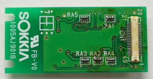
S6MWT11
Nov 01, 2007Bluetooth Module
Equipment Class
DSS - Part 15 Spread Spectrum Transmitter
S6MZ1
Nov 14, 2005Zeal Z1
Equipment Class
DSS - Part 15 Spread Spectrum Transmitter