S6MZ1Zeal Z1
Sokkia Topcon Co., Ltd.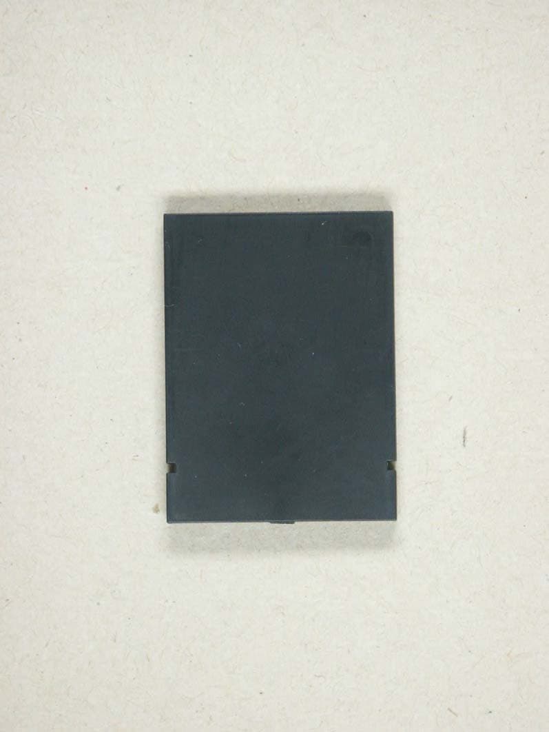
Click to zoom
Application Details
- Equipment Class
- DSS - Part 15 Spread Spectrum Transmitter
- Date of Grant
- Nov 14, 2005
- Application Purpose
- Original Equipment
- Date of Application
- Nov 14, 2005
- Equipment Note
- Zeal Z1
- Frequency Range
- 2402.00000000 - 2480.00000000
- Company
- Sokkia Topcon Co., Ltd.
- Country
- Japan
Documents & Files
Document Text
Text extracted from the exhibit documents filed with the FCC. Open a document above to read the original.
Users Manual
27-Sep-2005 ZEAL [Z1] User's manual Rev.01 27-Sep-2005 Revision history Rev Date Content Rev.01 27-Sep-2005 First edition 27-Sep-2005 Contents 1.General Description ......................................................................................................... 5 2.Product specification ........................................................................................................5 3.Pin Layout ........................................................................................................................ 6 4.Start Mode ........................................................................................................................ 6 Nomal Mode.......................................................................................................6 UART Setting Value Mode ................................................................................ 6 Firmware Rewriting Mode ................................................................................ 6 Automatic Scanning Mode ................................................................................ 6 Automatic Connection Mode ............................................................................. 7 5.Operation Mode ................................................................................................................7 Command Mode................................................................................................. 7 Online Mode....................................................................................................... 7 Park Mode..........................................................................................................7 Escape Mode...................................................................................................... 7 Scan Escape Mode ............................................................................................. 7 Scan Mode..........................................................................................................7 Standby Mode .................................................................................................... 7 6.Command.......................................................................................................................... 8 7.Result code........................................................................................................................ 9 Example:How to use “Zeal”............................................................................................... 10 27-Sep-2005 This device complies with Part 15 of the FCC Rules and RSS-210 of the IC Rules. Operation is subject to the following two conditions: (1) this device may not cause harmful interference, and (2) this device must accept any interference received, including interference that may cause undesired operation. FCC WARNING Changes or modifications not expressly approved by the party responsible for compliance could void the user’s authority to operate the equipment. FCC NOTICE This equipment has been tested and found to comply with the limits for a Class A digital device, pursuant to part 15 of the FCC Rules. These limits are designed to provide reasonable protection against harmful interference when the equipment is operated in a commercial environment. This equipment generates, uses and can radiate radio frequency energy and, if not installed and used in accordance with the instructions, may cause harmful interference to radio communications. Operation of this equipment in a residential area is likely to cause harmful interference in which case the user will be required to correct the interference at his own expense. This transmitter must not be co-located or operated in conjunction with any other antenna or transmitter. The antenna shown in this filing must not be co-located or operated in conjunction with any other antenna or transmitter. End users may not be provided with the module installation instructions. OEM integrators and end users must be provided with transmitter operating conditions for satisfying RF exposure compliance. For portable applications OEM integrators need no SAR evaluation. The max source-based time-averaged output of 0.46 mW is below the low threshold of 24mW for d < 2.5 cm. This equipment complies with FCC radiation exposure limits set forth for uncontrolled equipment and meets the FCC radio frequency (RF) Exposure Guidelines in Supplement C to OET65. This equipment has very low levels of RF energy that it is deemed to comply without testing of specificabsorption ratio (SAR). 27-Sep-2005 1.General Description This product is Bluetooth communication unit with UART I/F. 2.Product specification Item Content Product name ZEAL Product ID Z1 Version 1.2 Protocol L2CAP, SDP, RFCOMM Profile GAP, SPP, DUN Data Rate 723.2/57.6kbps(asymmetrical. Max) Modulation FHSS/GFSK 1Mbps, 1600hop/sec. Bluetooth I/F Output Power Class2 Protocol Asynchronous Serial Communication (Hardware Flow Control) Signal Level Supply power Baud rate 9600bps(Default) UART I/F Connector LPC-12FDS+C [HONDA TSUSHIN KOGYO CO., LTD.] Power Supply Voltage +2.9 - +3.6V DC (Single power supply) Operating Temperature Range -25 - +85°C Outside Dimensions 35.0mm(L), 26.0(W), 4.5mm(H) 27-Sep-2005 3.Pin Layout 1 PIO0 2 RXD 3 TXD 4 PIO1 5 GND 6 PIO2 7 RTS 8 CTS 9 PIO3 10 MODE0 11 MODE1 12 VCC *The signal is a pull-up on the inside in 51KΩ 4.Start Mode The start mode changes by the state of the mode pin when the power supply is turned on. Nomal Mode (MODE0,MODE1) = (1,1) UART communications setting:9600bps,Data8bit,StopBit 1,Parity none It starts by the command mode. UART Setting Value Mode (MODE0,MODE1) = (0,1) It starts by the UART setting to which internal is set, and it becomes a command mode. Firmware Rewriting Mode (MODE0,MODE1) = (0,0) When Farmuuea is rewritten with a special tool, it uses it. Automatic Scanning Mode (MODE0,MODE1) = (1,0) 27-Sep-2005 It starts by the UART setting to which internal i…
Text truncated - open the document above for the full version.
External Photos
ELECTRONIC TECHNOLOGY SYSTEMS DR.GENZ GMBH ETS Dr. Genz GmbH, Germany Registration number: G0M20510-9832-P-15 Page 1 of 9 Appendix A. Pictures ELECTRONIC TECHNOLOGY SYSTEMS DR.GENZ GMBH ETS Dr. Genz GmbH, Germany Registration number: G0M20510-9832-P-15 Page 2 of 9
ID Label/Location Info
27-Sep-2005 Label putting position Label UNIT:mm Label Layout
Internal Photos
ELECTRONIC TECHNOLOGY SYSTEMS DR.GENZ GMBH ETS Dr. Genz GmbH, Germany Registration number: G0M20510-9832-P-15 Page 3 of 9 ELECTRONIC TECHNOLOGY SYSTEMS DR.GENZ GMBH ETS Dr. Genz GmbH, Germany Registration number: G0M20510-9832-P-15 Page 4 of 9 ELECTRONIC TECHNOLOGY SYSTEMS DR.GENZ GMBH ETS Dr. Genz GmbH, Germany Registration number: G0M20510-9832-P-15 Page 5 of 9
RF Exposure Info
___________________________________________________________________________________ ETS Handelsregister: Bankverbindung: Electronic Technology Systems Dr. Genz GmbH Amtsgericht Frankfurt/Oder HRB 5151 Sparkasse Oder-Spree Storkower Strasse 38c Geschäftsführung: Dr. Dietmar Genz BLZ 170 550 50 D-15526 Reichenwalde b. Berlin Norbert Kaspar Kto. Nr. 3105165974 ELECTRONIC TECHNOLOGY SYSTEMS DR.GENZ GMBH RF Exposure Calculation Applicant: SOKKIA CO.,LTD. FCC ID: S6MZ1 The antenna shown in this filing must not be co-located or operated in conjunction with any other antenna or transmitter. End users may not be provided with the module installation instructions. OEM integrators and end- users must be provided with transmitter operating conditions for satisfying RF exposure compliance. This kind of equipment is below 60/frequency[GHz] mW(TCB Exclusion List)so that SAR testing is excluded. The Following calculation is the reference data for 20cm distance. integral Antenna requirement § 15.203). An intentional radiator shall be designed to ensure that no antenna other than that furnished by the responsible party shall be used with the device. The use of a permanently attached antenna or of an antenna that uses a unique coupling to the intentional radiator shall be considered sufficient to comply with the provisions of this section. The following information provides the minimum separation distance for the highest gain antenna provided with the “Z1“ as calculated from FCC OET Bulletin 65 Appendix A, Table (B) Limits for General Population / Uncontrolled Exposure. This calculation is based on the highest EIRP possible from the system, considering maximum power and antenna gain, and considering a 1.0mW/cm² uncontrolled exposure limit.
Test Report
ELECTRONIC TECHNOLOGY SYSTEMS DR. GENZ GMBH TEST - REPORT FCC RULES PART 15 / SUBPART C FCC ID: S6MZ1 Test report no.: G0M20510-9892-P-15 Certificate 1983-01 ELECTRONIC TECHNOLOGY SYSTEMS STORKOWER STRASSE 38C, D-15526 REICHENWALDE B. BERLIN DR. GENZ GMBH PHONE +49-33631-888 00 FAX +49-33631-888 660 ETS Dr. Genz GmbH, Germany Registration number: G0M20510-9892-P-15 Page 1 of 34 ELECTRONIC TECHNOLOGY SYSTEMS DR.GENZ GMBH TABLE OF CONTENTS 1 General information 1.1 Notes 1.2 Testing laboratory 1.3 Details of approval holder 1.4 Application details 1.5 Test item 1.6 Test standards 2 Technical test 2.1 Summary of test results 2.2 Test environment 2.3 Test equipment utilized 2.4 General Test Procedure 3 Test Results 3.1 Peak output power 3.2 Equivalent isotropic radiated power 3.3 RF exposure radiated emission 3.4 Antenna requirement 3.5 Out of band radiated emission 3.6 Transmitter radiated emissions in restricted bands 3.7 Spurious emissions (tx) 3.8 Carrier frequency separation 3.9 Number of hopping frequency 3.10 Time of occupancy 3.11 20 dB bandwidth 3.12 Band-edge compliance of RF emissions 3.13 Conducted measurement at (AC) power line ETS Dr. Genz GmbH, Germany Registration number: G0M20510-9892-P-15 Page 2 of 34 ELECTRONIC TECHNOLOGY SYSTEMS DR.GENZ GMBH 1 General Information 1.1 Notes The purpose of conformity testing is to increase the probability of adherence to the essential requirements or conformity specifications, as appropriate. The complexity of the technical specifications, however, means that full and thorough testing is impractical for both technical and economic reasons. Furthermore, there is no guarantee that a test sample which has Passed all the relevant tests conforms to a specification. Neither is there any guarantee that such a test sample will interwork with other genuinely open systems. The existence of the tests nevertheless provides the confidence that the test sample possesses the qualities as maintained and that is performance generally conforms to representative cases of communications equipment. The test results of this test report relate exclusively to the item tested as specified in 1.5. The test report may only be reproduced or published in full. Reproduction or publication of extracts from the report requires the prior written approval of the ELECTRONIC TECHNOLOGY SYSTEMS DR. GENZ GMBH. Tester: 26.10.2005 D. Hoppe Date ETS-Lab. Name Signature Technical responsibility for area of testing: 26.10.2005 N. Kaspar Date ETS Name Signature ETS Dr. Genz GmbH, Germany Registration number: G0M20510-9892-P-15 Page 3 of 34 ELECTRONIC TECHNOLOGY SYSTEMS DR.GENZ GMBH 1.2 Testing laboratory 1.2.1 Location ELECTRONIC TECHNOLOGY SYSTEM DR. GENZ GMBH (ETS) Storkower Straße 38c D-15526 Reichenwalde b. Berlin Germany Telefon : +49 33631 888 00 Telefax : +49 33631 888 66 1.2.2 Details of accreditation status A CCREDITED TESTING LABORATORY DAR-REGISTRATION NUMBER: TTI-P-G 126/96 ACCREDITED COMPETENT BODY DAR- REGISTRATION NUMBER: BPT-ZE-026/96 FCC FILED TEST LABORATORY REG. NO. 96970 BLUETOOTH QUALIFICATION TEST FACILITY (BQTF) A CCREDITED BY BLUETOOTH QUALIFICATION REVIEW BOARD INDUSTRY CANADA FILED TEST LABORATORY REG. NO. IC 3470 A2LA ACCREDITED Certificate Number 1983-01 1.3 Details of approval holder Name : SOKKIA Co., Ltd. Street : 260-63, Hase, Atsugi-shi, Town : 243-0036 Kanagawa Country : Japan Telephone : +81-465-82-7374 Fax : +81-465-82-5492 Contact : Mr. Keiji Tomita E-mail : [email protected] ETS Dr. Genz GmbH, Germany Registration number: G0M20510-9892-P-15 Page 4 of 34 ELECTRONIC TECHNOLOGY SYSTEMS DR.GENZ GMBH 1.4 Application details Date of receipt of application : 12.10.2005 Date of receipt of test item : 12.10.2005 Date of test : 12.10.2005 – 21.10.2005 1.5 Test item Description of test item : Zeal Type identification : Z1 Serial number : without Photos : See Appendix A Technical data Frequency band : 2.4GHz – 2.4835GHz Frequency ( ch A) : 2402 MHz Frequency (ch B) : 2441 MHz Frequency (ch C) : 2480 MHz Transmitter Vnom Power (ch A) : Conducted: -3.08 dBm Power (ch B) : Conducted: -3.84 dBm Power (ch C) : Conducted: -4.53 dBm Power supply : 3.3 V DC 120 V AC (AC/DC Adapter) Operating mode : duplex Type of modulation : FHSS Antenna type : Multilayer chip antenna Antenna gain : 3 dB (max) ETS Dr. Genz GmbH, Germany Registration number: G0M20510-9892-P-15 Page 5 of 34 ELECTRONIC TECHNOLOGY SYSTEMS DR.GENZ GMBH Host device : test board Classification : Fixed Device Mobile Device (Human Body distance > 20cm) Portable Device (Human Body distance < 20cm) Manufacturer: (if applicable) Name : ADC Technology, Inc. Street : NagoyaSeniBldg. 2-9-27 Nishiki Naka-ku Town : Nagoya Country : Japan Additional information: The test sample is designed as Bluetooth device. Its pseudorandom hopping scheme, authentication, receiver parameters, synchronization procedure and other parameters are determined by Bluetooth Core Specification. ETS Dr. Genz GmbH, Germany Registration number: G0M20510-9892-P-15 Page 6 of 34 ELECTRONIC TECHNOLOGY SYSTEMS DR.GENZ GMBH 1.6 Test standards Technical standard : FCC RULES PART 15 / SUBPART C § 15.247 2 Technical test 2.1 Summary of test results No deviations from the technical specification(s) were ascertained in the course : of the tests performed. or The deviations as specified in 2.5 were ascertained in the course of the tests performed. 2.2 Test environment Temperature : 25 o C Relative humidity content : 20 ... 75 % Air pressure : 86 ... 103 kPa Details of power supply : 3.3 V DC 120 V AC (AC/DC Adapter) Extreme conditions parameters: : test voltage - extreme min.: -- V (Vnom – 15%) max: -- V (Vnom + 15%) ETS Dr. Genz GmbH, Germany Registration number: G0M20510-9892-P-15 Page 7 of 34 ELECTRONIC TECHNOLOGY SYSTEMS DR.GENZ GMBH 2.3 Test equipment utilized No. Test equipment Type Manufacturer ETS 0001 ESD Gun SESD 30000 Schlöder ETS 0002 Test receiver ESVP Rohde & Schwarz ETS 0003 Diode power sensor NRV-Z2 Rohde & Schwarz ETS 0004 Spectrum …
Text truncated - open the document above for the full version.
Test Setup Photos
ELECTRONIC TECHNOLOGY SYSTEMS DR.GENZ GMBH ETS Dr. Genz GmbH, Germany Registration number: G0M20510-9832-P-15 Page 6 of 9 ELECTRONIC TECHNOLOGY SYSTEMS DR.GENZ GMBH ETS Dr. Genz GmbH, Germany Registration number: G0M20510-9832-P-15 Page 7 of 9 ELECTRONIC TECHNOLOGY SYSTEMS DR.GENZ GMBH ETS Dr. Genz GmbH, Germany Registration number: G0M20510-9832-P-15 Page 8 of 9 ELECTRONIC TECHNOLOGY SYSTEMS DR.GENZ GMBH ETS Dr. Genz GmbH, Germany Registration number: G0M20510-9832-P-15 Page 9 of 9
Contact Information
Applicant
Keiji Tomita(General Manager)
Test Firm
Eurofins Product Service GmbHRobert Kschiwan-Kaspar
Technical Specifications
| # | Rule Parts | Frequency Range | Power Output |
|---|---|---|---|
| 1 | 15C | 2.40 GHz - 2.48 GHz | 500.00 µW |
Other Applications from Sokkia Topcon Co., Ltd.
S6MWT11
Nov 01, 2007Bluetooth Module
Equipment Class
DSS - Part 15 Spread Spectrum Transmitter
S6MSMBT1
Sep 25, 2006Bluetooth module
Equipment Class
DSS - Part 15 Spread Spectrum Transmitter