S7USBCA5120Multimedia Equipment: SlingCatcher Model:SC100-100
Sling Media. Inc,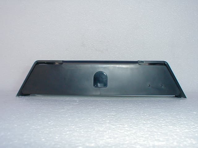
Click to zoom
Application Details
- Equipment Class
- JBP - Part 15 Class B Computing Device Peripheral
- Date of Grant
- Sep 03, 2007
- Application Purpose
- Original Equipment
- Date of Application
- Sep 03, 2007
- Equipment Note
- Multimedia Equipment: SlingCatcher Model:SC100-100
- Company
- Sling Media. Inc,
- Country
- United States
Documents & Files
Document Text
Text extracted from the exhibit documents filed with the FCC. Open a document above to read the original.
Users Manual
SLINGCATCHER USER GUIDE Copyright © 2007 Sling Media, Inc. Sling Media, Slingbox, SlingCatcher, SlingLink, SlingPlayer, SlingPlayer Mobile, SlingProjector, SlingSync, and SlingStream are the registered Trademarks of Sling Media, Inc. Other products and companies mentioned are the Trademarks of their respective owners and not Sling Media, Inc. Windows is a registered trademark of Microsoft Corporation in the United States and/or other countries. HDMI and High Definition Multimedia Interface are trademarks or registered trademarks of HDMI Licensing, LLC. Apple, Mac and Macintosh are registered trademarks of Apple Inc. Dolby is a registered trademark of Dolby Laboratories. All other products and services, screen images, logos, and trademarks are the property of their respective owners. All names used are fictitious and the similarity to any person living or dead is strictly coincidental. All video images are simulated. We have made every effort to ensure that the information in this User Guide is accurate. Sling Media, Inc. is not responsible for clerical or printing errors. WHAT’S IN THE BOX : SlingCatcher Composite Video & Analog Audio Cables Ethernet CablePower Adapter Remote Control & 2 AAA Batteries WELCOmE! Thank you for purchasing SlingCatcher. SlingCatcher allows you to watch digital video on your TV. With the included remote control, you can sit back on your couch and watch video from your Slingbox, or movies and Internet video from your PC. We’ve designed this set up procedure to cover most situations. If you have a more complex home theater system, see the manuals that came with your equipment for set-up information. If you don’t have your manual, many of them are available on the web sites of the manufacturers. 1 BEFORE YOU BEGIN TVRouter Slingbox Windows PC Flashlight WHAT YOU NEED TO SETUP SLINGCATCHER : OPTIONAL EQUIPMENT : 2 • A flashlight to help you see behind your TV. • A TV with composite video, S-video, component video, or HDMI inputs. • A broadband Internet connection (cable or DSL modem) connected to a home network (wired or wireless). Note: For ease-of-use, performance and convenience, Sling Media recommends that you use wired Ethernet or SlingLink TM TURBO to connect SlingCatcher to your home network. Alternatively, you can use SlingLink WIRELESS. It plugs into a USB port on the back of the SlingCatcher and allows you to connect SlingCatcher to your wireless router. SlingLink TURBO and SlingLink WIRELESS are sold separately. Visit http://www.slingmedia.com/slinglink for more information. One or both of these: • A Slingbox on your home network (LAN) or on the Internet (WAN), if you want to watch video from your Slingbox on your TV. • A Windows PC to run the SlingCatcher Desktop software, if you want to sync or stream video from your PC to the SlingCatcher and watch it on the TV. Note: SlingCatcher requires an optional USB 2.0 storage device (hard disk drive or flash memory stick) to support the sync functionality. Visit http://www.slingcatcher.com for more information. Digital audio, HDMI, S-video and component cables may be needed, depending on how you choose to connect SlingCatcher. 3 STEP 1 : INSERT bATTERIES IN ThE REMOTE Place the batteries in the remote control by removing the rear cover of the remote and inserting the batteries. Use the diagram in the battery compartment to make sure you insert the batteries correctly. Once you’ve installed the batteries properly, the red light will flash when you press the OK button. STEP 3 : CONNECT ThE AUdIO CAbLES 1. First, choose the device that you want to send sound to. You can set up SlingCatcher to send audio to your TV, your stereo or your A/V receiver. To connect the cables properly, it’s easiest to start by looking at the back of your TV, stereo or A / V receiver. Note: Some TVs have their connections organized into sets of inputs (INPUT 1, INPUT 2 or AUX 1, AUX 2, etc.). If your TV has these, write down the input set that you use. You may need to change the Input source setting on your TV later in this set up procedure. SETTING UP SLINGCATCHER STEP 2 : PLACE SLINgCATChER NEAR yOUR TV Remove SlingCatcher from the packaging and place it near your TV. For the remote control to work properly, the entire front of the SlingCatcher should be visible from where you watch TV and it must not be blocked. Do not place your SlingCatcher on or near anything that gets hot, such as a stereo amplifier, spotlight, transformer, radiator, etc. Also, don’t place anything on top of your SlingCatcher. IMPORTANT: Before you plug SlingCatcher into an electrical outlet, read the safety information in the included “SlingCatcher Safety, Regulatory, and Legal Information” booklet. That booklet also includes important safety instructions on cleaning your SlingCatcher. 4 TIP : You may need to refer to the manual for your TV, stereo or A/V receiver to see information about the connections. Don’t panic if you don’t have the manual. Many manufacturers have these manuals on their web sites. 2. Next, choose a type of audio connection. There are three kinds of audio connections: analog, digital and HDMI (High-Definition Multimedia Interface). Analog provides good sound. Digital or HDMI provide the best sound. Make sure that the device for audio has the kind of available audio connections that you want to use. ANALOG : Analog audio connections are usually red and white. The red connection is for the right channel and white is for the left channel. If you see connectors on your audio source, connect the matching cables to SlingCatcher and then to the INPUT connections on the audio device that you’ve chosen. Often the analog sound cables include a yellow connector for video. Don’t connect this yellow connector at this time. DIGITAL : Digital audio connections are usually orange. These connections are also called S/PDIF (Sony/Philips Digital Interface) or Coaxial S/PDIF. Many manufacturers use these connections. If the audio device for audio that you’ve …
Text truncated - open the document above for the full version.
External Photos
Sling Media, Inc. FCC ID: S7USBCA5120 External Photos Top View Sling Media, Inc. FCC ID: S7USBCA5120 External Photos Front View Sling Media, Inc. FCC ID: S7USBCA5120 External Photos Bottom View Sling Media, Inc. FCC ID: S7USBCA5120 External Photos
ID Label/Location Info
LABEL AND LOCATION: LOCATED ON THE BOTTOM OF THE UNIT
Internal Photos
Sling Media, Inc. FCC ID: S7USBCA5120 Internal Photos Sling Media, Inc. FCC ID: S7USBCA5120 Internal Photos Sling Media, Inc. FCC ID: S7USBCA5120 Internal Photos
Test Report
FCC Class B Report Number: M70822A1 Page 1 of 16 ELECTRO MAGNETIC TEST, INC. 1547 Plymouth Street, Mountain View, CA 94043 Tel: (650) 965-4000 Fax: (650) 965-3000 FCC PART 15, SUBPART B CLASS B TEST REPORT for the SlingCatcher MODEL: SC100-100 Prepared for SLING MEDIA, INC. 1051 E. HILLSDALE BLVD., SUITE 500 FOSTER CITY, CALIFORNIA 94404 Prepared by: ALIKA HIRANO Approved by: KEVIN BOTHMANN ELECTRO MAGNETIC TEST, INC. 1547 PLYMOUTH STREET MOUNTAIN VIEW, CALIFORNIA 94043 (650) 965-4000 DATE: AUGUST 27, 2007 REPORTAPPENDICESTOTAL BODYABC PAGES16163237 This report shall not be reproduced except in full, without the written approval of Electro Magnetic Test, Inc. FCC Class B Report Number: M70822A1 Page 2 of 16 ELECTRO MAGNETIC TEST, INC. 1547 Plymouth Street, Mountain View, CA 94043 Tel: (650) 965-4000 Fax: (650) 965-3000 TABLE OF CONTENTS SECTIONTITLEPAGE GENERAL REPORT SUMMARY04 SUMMARY OF TEST RESULTS05 1.PURPOSE06 2.ADMINISTRATIVE DATA07 2.1Location of Testin g07 2.2Traceabilit y Statement07 2.3Co gnizant Personnel07 2.4Date Test Sam ple was Received07 2.5Disposition of the Test Sample07 2.6Abbreviations and Acronyms07 3.APPLICABLE DOCUMENTS08 4.DESCRIPTION OF TEST CONFIGURATIONS09 4.1Descri ption of Test Configuration - EMI09 4.1.1Cable Construction and Termination10 5.LIST OF EUT , ACCESSORIES AND TEST EQUIPMENT11 5.1EUT and Accessory List11 5.2EMI Test E quipment12 6.TEST SITE DESCRIPTION13 6.1Test Facilit y Description13 6.2EUT Mounting, Bonding and Grounding13 7.TEST PROCEDURES14 7.1RF Emissions14 7.1.1Conducted Emissions Test14 7.1.2Radiated Emissions Test15 8.CONCLUSIONS / COMPLIANCE STATEMENT16 FCC Class B Report Number: M70822A1 Page 3 of 16 ELECTRO MAGNETIC TEST, INC. 1547 Plymouth Street, Mountain View, CA 94043 Tel: (650) 965-4000 Fax: (650) 965-3000 LIST OF APPENDICES APPENDIXTITLE A Radiated and Conducted Emissions Data Sheets B Test Setup Diagrams C Additional Models Covered Under This Report LIST OF FIGURES FIGURETITLE 1 Conducted Emissions Test Setup 2 Plot Map And Layout of Test Site FCC Class B Report Number: M70822A1 Page 4 of 16 ELECTRO MAGNETIC TEST, INC. 1547 Plymouth Street, Mountain View, CA 94043 Tel: (650) 965-4000 Fax: (650) 965-3000 GENERAL REPORT SUMMARY This electromagnetic emission test report is generated by Electro Magnetic Test, Inc., which is an independent testing and consulting firm. The test report is based on testing performed Electro Magnetic Test, Inc. personnel according to the measurement procedure described in the test specification given below and in the "Test Procedures" section of this report. The measurement data and conclusions appearing herein relate only to the sample tested and this report may not be reproduced in any form unless done so in full. This report must not be used to claim product certification, approval, or endorsement by NVLAP, NIST, or any agency of the U.S. Federal Government. Electro Magnetic Test, Inc. is recognized by the following agencies for performing EMI/EMC testing: COUNTRYAGENCYIDENTIFYING # USAFederal Communications Commission (FCC) (EMT’s test site is recognized by the FCC) Registration Number: 90576 USA, Canada, Taiwan, Australia/New Zealand, European Community National Voluntary Lab Accreditation Program (NVLAP) (EMT is accredited by NVLAP. A copy of the NVLAP Scope Of Accreditation is available upon request.) Lab Code: 200147-0 CanadaIndustry CanadaFile No.: IC 2804 JapanVoluntary Control Council For Interference (VCCI)See Below Open Field Test Site Registration NumberR-589 Conducted Emissions Test Site Registration NumberC-604 KoreaMinistry of Information and Communication’s Radio Research Laboratory (RRL) under the Asia Pacific Economic Cooperation (APEC) Mutual Recognition Arrangement (A copy of the Scope Of Accreditation is available upon request) US0036 TaiwanBureau Of Standards, Metrology and Inspection (BSMI)Reference Number: SL2-IN-E-1024 Australia / New ZealandAustralian Communications Authority (AUSTEL)* European CommunityTUV Rheinland (EMC for the European Community)* *These agencies do not issue an identifying number to test labs. FCC Class B Report Number: M70822A1 Page 5 of 16 ELECTRO MAGNETIC TEST, INC. 1547 Plymouth Street, Mountain View, CA 94043 Tel: (650) 965-4000 Fax: (650) 965-3000 GENERAL REPORT SUMMARY (CONTINUED) Device Tested:SlingCatcher Model: SC100-100 S/N: N/A Product Description:The EUT is a breakthrough consumer electronics device that takes multimedia content either from a USB storage device or through the Ethernet port which gives a video/audio output to the TV. The EUT can be controlled using the included infrared remote control. Modifications:The EUT was not modified during the testing. Manufacturer:Sling Media, Inc. 1051 E. Hillsdale Blvd., Suite 500 Foster City, California 94404 Test Date(s):August 22, 2007 Test Specifications:EMI requirements Limits: CISPR 22: 1997 plus A1:2000 & A2:2002 Class B FCC Title 47, Part 15 Subpart B, Class B Test Procedure: ANSI C63.4: 2003 Test Deviations:The test procedure was not deviated from during the testing. The decoupling ferrite clamp was not used on the I/O cable connecting to remote equipment, since this requirement has been postponed until 2008. This requirement might be removed from the standard in the future. SUMMARY OF TEST RESULTS TESTDESCRIPTIONRESULTS 1Conducted RF Emissions, 150 kHz - 30 MHz.Complies with the Class B limits of CISPR 22: 1997 plus A1:2000 & A2:2002 2Radiated RF Emissions, 30 MHz - 1000 MHz.Complies with the Class B limits of CISPR 22: 1997 plus A1:2000 & A2:2002 3Radiated RF Emissions, 1 GHz - 2 GHz.Complies with the Class B limits of FCC Title 47, Part 15 Subpart B FCC Class B Report Number: M70822A1 Page 6 of 16 ELECTRO MAGNETIC TEST, INC. 1547 Plymouth Street, Mountain View, CA 94043 Tel: (650) 965-4000 Fax: (650) 965-3000 1.PURPOSE This document is a qualification test report based on the Electromagnetic Interference (EMI) tests performed on the SlingCatcher, Model: SC100-100. The EMI measurements wer…
Text truncated - open the document above for the full version.
Test Setup Photos
FCC ID: S7USBCA5120 ELECTRO MAGNETIC TEST, INC. 1547 Plymouth Street, Mountain View, CA 94043 Tel: (650) 965-4000 Fax: (650) 965-3000 FRONT VIEW SLING MEDIA, INC. SlingCatcher MODEL: SC100-100 CISPR 22/FCC CLASS B - RADIATED EMISSIONS PHOTOGRAPH SHOWING THE EUT CONFIGURATION FOR MAXIMUM EMISSIONS FCC ID: S7USBCA5120 ELECTRO MAGNETIC TEST, INC. 1547 Plymouth Street, Mountain View, CA 94043 Tel: (650) 965-4000 Fax: (650) 965-3000 REAR VIEW SLING MEDIA, INC. SlingCatcher MODEL: SC100-100 CISPR 22/FCC CLASS B - RADIATED EMISSIONS PHOTOGRAPH SHOWING THE EUT CONFIGURATION FOR MAXIMUM EMISSIONS FCC ID: S7USBCA5120 ELECTRO MAGNETIC TEST, INC. 1547 Plymouth Street, Mountain View, CA 94043 Tel: (650) 965-4000 Fax: (650) 965-3000 FRONT VIEW SLING MEDIA, INC. SlingCatcher MODEL: SC100-100 CISPR 22 CLASS B - CONDUCTED EMISSIONS PHOTOGRAPH SHOWING THE EUT CONFIGURATION FOR MAXIMUM EMISSIONS FCC ID: S7USBCA5120 ELECTRO MAGNETIC TEST, INC. 1547 Plymouth Street, Mountain View, CA 94043 Tel: (650) 965-4000 Fax: (650) 965-3000 REAR VIEW SLING MEDIA, INC. SlingCatcher MODEL: SC100-100 CISPR 22 CLASS B - CONDUCTED EMISSIONS PHOTOGRAPH SHOWING THE EUT CONFIGURATION FOR MAXIMUM EMISSIONS
Contact Information
Applicant
Ian Schroeder(Hardware Engineer)
Technical Contact
Sling Media Inc.Raghu Tarra
[email protected]650-293-8009
1051 E. Hillsdale Blvd., Suite 500 · Foster City, California · United States
Test Firm
Electro Magnetic Test, Inc.Jay Gandhi
Technical Specifications
| # | Rule Parts | Frequency Range | Power Output |
|---|---|---|---|
| 1 | 15B | - | - |
Other Applications from Sling Media. Inc,
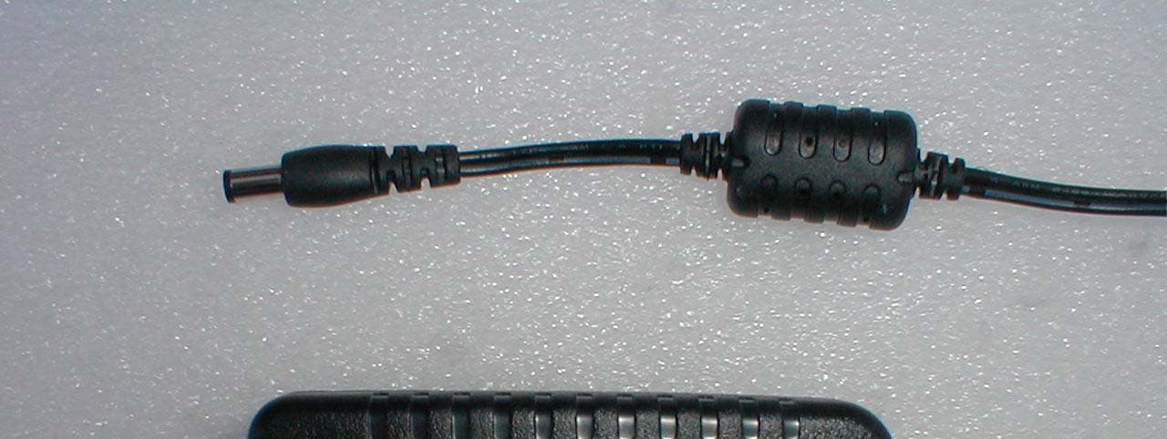
S7USBPB2849
Sep 03, 2007Multimedia Equipment:Slingbox SOLO Model:SB260-100
Equipment Class
JBP - Part 15 Class B Computing Device Peripheral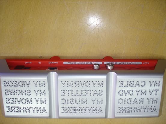
S7USBPB1539
Oct 09, 2006Multimedia Equipment
Equipment Class
JBP - Part 15 Class B Computing Device PeripheralS7USBPB2445
Sep 12, 2006Multimedia Equipment-Slingbox AV Model# SB240-100
Equipment Class
JBP - Part 15 Class B Computing Device PeripheralS7USBPB2041
Sep 12, 2006Multimedia Equipment-Slingbox PRO Model# SB200-100
Equipment Class
JBP - Part 15 Class B Computing Device PeripheralS7USBPB2243
Sep 12, 2006Multimedia Equipment-SlingboxTuner Model#SB220-100
Equipment Class
JBP - Part 15 Class B Computing Device Peripheral