S7Y-AGS1600-001AGS1600 Position Sensing Radar
Navtech Radar Ltd
Click to zoom
Application Details
- Equipment Class
- FDS - Part 15 Field Disturbance Sensor
- Date of Grant
- Apr 03, 2013
- Application Purpose
- Original Equipment
- Date of Application
- Apr 03, 2013
- Equipment Note
- AGS1600 Position Sensing Radar
- Frequency Range
- 76247.00000000 - 76683.00000000
- Company
- Navtech Radar Ltd
- Country
- United Kingdom
Documents & Files
Document Text
Text extracted from the exhibit documents filed with the FCC. Open a document above to read the original.
Users Manual
AdvanceGuard Hardware Installation Guide Document version 1.2e Hardware Installation Guide 1 Contents 2 Welcome 2 Essential items 3 Parts 4 Creating an installation 4 Mounting a radar sensor 4 Mounting the enclosure and power supply 5 Levelling a sensor 7 Connecting a radar sensor 8 Connecting other items 8 Connecting cameras 9 Connecting trigger inputs and alarm outputs 10 Confirming sensor operation 10 Preparing your computer 10 Connecting your computer 11 Testing a sensor 15 Appendices 15 Appendix 1 - FAQ 16 Appendix 2 - Radio frequency energy statement Hardware Installation Guide 2 Welcome The Navtech Radar AdvanceGuard system provides high integrity detection, tracking and intelligent alarm generation for wide area intrusion detection systems. This guide concentrates on installing the key hardware components: Radar sensors; cameras and external inputs/ outputs. As part of the installation process this guide also covers how to test the radar sensor output and adjust its positioning for optimum performance. For details about the witness application group, please refer to the companion Witness Commissioning Guide. Power Supply Unit Radar Processing Unit External inputs Alarm outputs Adam 6060 Essential items The following are the essential additional items that you will need to install a radar sensor: • Laptop computer running Radar View software, • Shielded Cat5E patch lead, • Digital level, • 25m² radar target and tripod, 2 off, • 10mm spanner, • Pair of 2 way radios, • An assistant. Radar & camera models may differ from illustrations Hardware Installation Guide 3 Parts This page lists the main parts that are commonly used in most radar installations (mount poles are not shown). Note that these images are for illustrative purposes only, as items/casing shapes are subject to change. W- Series radar sensor I-Series radar sensor RPU (Radar Processing Unit) IP-rated equipment enclosure Adam 6060 input/output unit Radar sensor power cable (bare ended at enclosure end) Mil spec shroud for radar sensor data connection Radar sensor power supply Hardware Installation Guide 4 Creating an installation Mounting a radar sensor Navtech Radar Limited supply a range of radar sensors and mounting posts to suit various installation sites. The two most common posts are: • Standard mount post which provides a height adjustment of between 1.35m to 1.89m (measured beam height for a W200/500/AGS800/1600 sensor) and can optionally be fitted with a CCTV camera arm. • Telescopic mount post which can extend to 4 metres in height and is suitable for the X variant sensor. For the standard mount posts you should aim to initially position the sensor so that its metal collar is at roughly 1.5 metres above ground level so that the post is at the mid- dle of its vertical adjustment range. During commissioning it may be necessary to raise or lower the sensor to clear obstacles or allow for the local terrain. Note: If you are creating your own mount post, you are recommended to include at least 50 centimetres of vertical adjustment built into the post to allow for local topog- raphy. Mounting the enclosure and power supply The IP-rated equipment enclosure is normally mounted at the base of the radar post and is used to house the radar power supply unit, however, other items may also need to be housed within the enclosure: • If the radar is mounted more than 70 metres from the RPU server then it is recom- mended that a fibre optic ethernet link is used. In this case a media converter would also need to be housed within the enclosure. • If there is a camera option on the post then the camera power supply unit and a possibly a video encoder will also need to be housed. IMPORTANT: To prevent floating voltage levels on the low output of the radar sensor power supply unit, link the 0v output to earth. IMPORTANT: Note that each radar is supplied with a pressure plug, which is left loose during freight. This plug should be reinserted at install time such that the radar is kept pressurised and maintains its ingress protection. Failure to insert the pressure plug could invalidate the warranty in the event of damage. AC Simplified wiring diagram Hardware Installation Guide 5 Levelling a sensor Due to the very narrow beams (1 or 2 degrees) used by most radar sensors, it is impor- tant that each sensor is level in relation to the area that it surveys. Level in this sense may not mean absolutely horizontal. For instance, if the site has a continual slope it may prove beneficial to incline the sensor in line with the slope to ensure that targets are correctly tracked. The exaggerated examples below show how a sensor with an incorrect incline could miss targets which are lower down the slope: A B A B The horizontal radar sensor misses target B. The inclined radar sensor locates both targets. To make sensor levelling adjustments The sensor mounting plate allows for a simple yet effective method to fine tune the incline of the sensor. For each of the mounting holes, the bolt is fed from underneath and locked onto the mounting plate with a nut. Two more nuts and washers are then used above and below the sensor plate so that the sensor can be positioned anywhere up or down the bolt thread, as necessary. We recommend that you begin with the sensor completely horizontal and then carefully adjust it to suit the conditions using the method described next. Hardware Installation Guide 6 Target BTarget A Radar sensor To adjust the sensor level The recommended procedure to check for the optimum incline is to use two radar targets mounted on tripods. 1 Adjust each target to a height of 1.3 metres above ground level and locate them on opposites sides of the sensor at suitable distances (e.g. 30m or further). 2 Connect a portable computer to the radar sensor and then use the procedure To use SPx RadarView (within the section Testing a sensor) to view the resulting scan: Your aim is to ensure that both targets can be clearly seen by the radar sensor.…
Text truncated - open the document above for the full version.
Attestation Statements
TRL 51F047 iss04 LETTER OF AGENCY 11 March 2013 TRaC Global Ltd. 100 Frobisher Business Park Malvern Worcestershire WR14 1BX UK To Whom It May Concern: We certify that we are not subject to denial of federal benefits, that includes FCC benefits, pursuant to Section 5301 of the Anti-Drug Abuse ACT of 1988, U.S.C. 862. Further, no party, as defined in 47 CFR 1.2002(b), to the application, is subject to denial of federal benefits, that includes FCC benefits. Thank you for your attention to this matter. Yours faithfully Navtech Radar Ltd Richard Poulton Navtech Radar Ltd Unit 16 Home Farm Ardington Wantage Oxfordshire, UK OX12 8PD Tel: +44(0)1235 832419 Fax: +44(0)1235 821675 [email protected] www.navtechradar.com
Cover Letter(s)
TRL 51F050 iss02B REQUEST FOR CONFIDENTIALITY IN ACCORDANCE WITH FCC RULE 0.459 11 March 2013 TRaC Global 100 Frobisher Business Park Leigh Sinton Road Malvern Worcestershire WR14 1BX UK RE: Certification Application FCC ID: S7Y-AGS1600-001 To Whom It May Concern: Please be advised that the following information is to be held confidential on behalf of Navtech Radar Ltd. • Parts list / Bill of Materials • Schematic Diagrams • PCB Layout Diagrams • Operational Description • Radio RF Block Diagram • Internal Photographs The application contains technical information which Navtech Radar Ltd deems to be trade secrets and propriety. If made public, the information might be used to the disadvantage of the applicant in the market place. Thank you for your attention to this matter. Yours faithfully Navtech Radar Ltd Richard Poulton Navtech Radar Ltd Unit 16 Home Farm Ardington Wantage Oxfordshire, UK OX12 8PD Tel: +44(0)1235 832419 Fax: +44(0)1235 821675 [email protected] www.navtechradar.com
Cover Letter(s)
TRL 51F050 iss04 Go on then show me then REQUEST FOR CONFIDENTIALITY – INTERNAL PHOTOS Date 12/03/2013 TRaC GLOBAL LTD. 100 Frobisher Business Park Malvern Worcestershire WR14 1BX UK RE: Request for confidentiality FCC ID: S7Y-AGS1600-001 To Whom It May Concern: Please be advised that we request all internal photos to be kept confidential, this product is: • A non-consumer device, serviced only by Navtech Radar Ltd or a designated technician • The warnings on the outside of the device state that warranty is void if unopened by unauthorised personnel • The main boards are covered by EMC cans under the radome Yours faithfully Navtech Radar Ltd Mr Richard Poulton Navtech Radar Ltd Unit 16 Home Farm Ardington Wantage Oxfordshire, UK OX12 8PD Tel: +44(0)1235 832419 Fax: +44(0)1235 821675 [email protected] www.navtechradar.com
Cover Letter(s)
TRL 51F050 iss04 D ECLARATION OF SIMILARITY Date 12/03/2013 TRaC GLOBAL LTD. 100 Frobisher Business Park Malvern Worcestershire WR14 1BX UK RE: Declaration of Similarity FCC ID: S7Y-AGS1600-001 To Whom It May Concern: Please be advised that the models AGS1600 and AGS1600-X are electronically identical, all RF measurements and test results are exactly the same. The difference between the two models is the antenna. The AGS1600 has a 1°x3° Antenna beam shape and the AGS1600-X has a 1°x25° and therefore a lower EIRP measurement than the AGS1600. Thank you for your attention to this matter. Yours faithfully Navtech Radar Ltd Mr Richard Poulton Navtech Radar Ltd Unit 16 Home Farm Ardington Wantage Oxfordshire, UK OX12 8PD Tel: +44(0)1235 832419 Fax: +44(0)1235 821675 [email protected] www.navtechradar.com
Test Report
TRaC RADIO TEST REPORT FOR Navtech Radar Ltd ON AGS1600 77 GHz Position Sensing Radar DOCUMENT NO. TRA-011336-W-US-1 TRaC Radio Test Report: TRA-011336-W-US-1 2 TRaC Wireless Test Report : TRA-010248-W-US-1 Applicant : Navtech Radar Ltd Apparatus : AGS1600 77 GHz Position Sensing Radar Specification(s) : CFR47 Part 15 C 15.253: October 2012 FCCID : S7Y-AGS1600-001 Purpose of Test : Certification Authorised by : : Radio Product Manager Issue Date : 4 th April 2013 Authorised Copy Number : PDF Total number of pages: 41 TRaC Radio Test Report: TRA-011336-W-US-1 Contents Section 1: Introduction 4 1.1 General 4 1.2 Tests Requested By 5 1.3 Manufacturer 5 1.4 Apparatus Assessed 6 1.5 Test Result Summary 7 1.6 Notes Relating To The Assessment 8 1.7 Deviations from Test Standards 8 Section 2: Measurement Uncertainty 9 2.1 Measurement Uncertainty Values 9 Section 3: Modifications 10 3.1 Modifications Performed During Assessment 10 Appendix A: Formal Emission Test Results 11 A1 Radiated Carrier power 12 A2 Transmit Radiated Electric Field Emissions below 40 GHz 13 A3 Transmit Radiated Electric Field Emissions above 40 GHz 15 A4 Transmitter Bandwidth 17 A5 Unintentional Radiated Electric Field Emissions - 15.109 (Receiver/Digital circuitry) 18 A6 ac Power Line Conducted Emissions 15.107 (Receiver/Digital circuitry) 20 Appendix B: Supporting Graphical Data 23 Appendix C: Additional Test and Sample Details 29 Appendix D: Additional Information 35 Appendix E: Photographs and Figures 36 Appendix F: MPE Calculation 40 3 TRaC Radio Test Report: TRA-011336-W-US-1 Section 1: Introduction 1.1 General This report contains an a ssessment of an apparatus against Radio Test Standards based upon tests carried out on samples submitted to the Laboratory. Test performed at: TRaC Telecoms & Radio [ X ] Unit E South Orbital Trading Park Hedon Road Hull, HU9 1NJ. United Kingdom. Telephone: +44 (0) 1482 801801 Fax: +44 (0) 1482 801806 Email: [email protected] Web site: http://www.tracglobal.com Tests performed by: K J Anderson Report author: K J Anderson This report must not be reproduced except in full without prior written permission from TRaC Global. 4 TRaC Radio Test Report: TRA-011336-W-US-1 1.2 Tests Requested By This testing in this report was requested by: Navtech Radar Ltd 16 Home Farm Ardington Wantage Oxfordshire OX12 8PD United Kingdom 1.3 Manufacturer As Above 5 TRaC Radio Test Report: TRA-011336-W-US-1 1.4 Apparatus Assessed The following apparatus was assessed between: 01/11/12 and 17/11/12 AGS1600 77GHz Position Sensing Radar The above consists of an swept frequency transmitter / receiver operating in the 76 to 77 GHz ISM band. 6 TRaC Radio Test Report: TRA-011336-W-US-1 1.5 Test Result Summary Full details of test results are contained within Appendix A. The following table summarises the results of the assessment. The statements relating to compliance with the standards below apply ONLY as qualified in the notes and deviations stated in sections 1.6 to 1.7 of this test report. Full details of test results are contained within Appendix A. The following table summarises the results of the assessment. Test Type Regulation Measurement standard Result Radiated Carrier Power Title 47 of the CFR: Part 15 Subpart C; 15.253(d) ANSI C63.4 Pass Radiated spurious emissions below 40 GHz Title 47 of the CFR: Part 15 Subpart C; 15.253(e)(1) ANSI C63.4 Pass Radiated Spurious Emissions above 40 MHz Title 47 of the CFR: Part 15 Subpart C; 15.253(e)(2)(ii) and 15.253(e)(3) ANSI C63.4 Pass Transmitter bandwidth Title 47 of the CFR: Part 15 Subpart C; 15.253(f) - Pass Radiated Spurious Emissions from digital circuitry Title 47 of the CFR: Part 15 Subpart B; 15.109 ANSI C63.4 Pass RF Safety Title 47 of the CFR : Part 2.1091 and Part 15 Subpart C; 15.253(g) - Pass 7 TRaC Radio Test Report: TRA-011336-W-US-1 1.6 Notes Relating To The Assessment With regard to this assessment, the following points should be noted: The results contained in this report relate only to the items tested and were obtained in the period between the date of initial receipt of samples and the date of issue of the report. The apparatus was set up and exercised using the configurations, modes of operation and arrangements defined in this report only. Particular operating modes, apparatus monitoring methods and performance criteria required by the standards tested to have been performed except where identified in Section 1.7 of this test report (Deviations from Test Standards). For emissions testing, throughout this test report, “Pass” indicates that the results for the sample as tested were below the specified limit (refer also to Section 2, Measurement Uncertainty). Where relevant, the apparatus was only assessed using the monitoring methods and susceptibility criteria defined in this report. All testing with the exception of testing at the Open Area Test Site was performed under the following environmental conditions: Temperature : 17 to 23 C Humidity : 45 to 75 % Barometric Pressure : 86 to 106 kPa All dates used in this report are in the format dd/mm/yy. This assessment has been performed in accordance with the requirements of ISO/IEC 17025. 1.7 Deviations from Test Standards There were no deviations from the standards test ed to. 8 TRaC Radio Test Report: TRA-011336-W-US-1 Section 2: Measurement Uncertainty 2.1 Measurement Uncertainty Values For test dat a recorded, the following measurement uncertainty was calculated: Radiated Electric Field Emissions Quantity Range Quantity Expanded Uncertainty 9kHz to 150 kHz Amplitude dB(μV/m) ±1.6dB 150 kHz to 30 MHz Amplitude dB(μV/m) ±2.1dB 30MHz to 300MHz Horizontal Amplitude dB(μV/m) ±5.1dB 30MHz to 300MHz Vertical Amplitude dB(μV/m) ±5.2dB 300MHz to 1GHz Horizontal Amplitude dB(μV/m) ±5.4dB 300MHz to 1GHz Vertical Amplitude dB(μV/m) ±5.2dB 1GHz to 18GHz Horizontal Amplitude dB(μV/m) ±4.4dB 1GHz to 18GHz Vertical Amplitude dB(μV/m) ±4.4dB 18GHz to 26.5GHz Horizontal Amplitude dB(μV/m) ±4.2dB 18GHz to 26…
Text truncated - open the document above for the full version.
Test Setup Photos
TRA-011336-01_AGS1600
Contact Information
Applicant
Philip Avery(Mr)
Test Firm
Element Materials Technology Warwick LtdMax Leach
Technical Specifications
| # | Rule Parts | Frequency Range | Power Output |
|---|---|---|---|
| 1 | 15.253 | 76.25 GHz - 76.68 GHz | - |
Other Applications from Navtech Radar Ltd

S7Y-MV1K
Jun 14, 2020KTS350-X
Equipment Class
TNB - Licensed Non-Broadcast Station Transmitter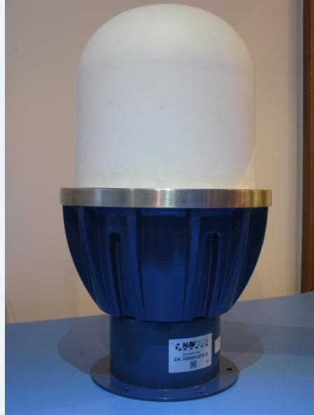
S7Y-AGS800-001
Apr 16, 2013AGS800 Position Sensing Radar
Equipment Class
FDS - Part 15 Field Disturbance Sensor