FCCID.CO- FCC ID Database
HomeCompaniesEquipment ClassesSearch

© 2026 FCC ID Database. All rights reserved.

AboutContactData sourced from FCC public records
  1. Home/
  2. Channel D Solutions, Inc./
  3. S85-DAS2400

S85-DAS2400Antenna Distribution System

Channel D Solutions, Inc.
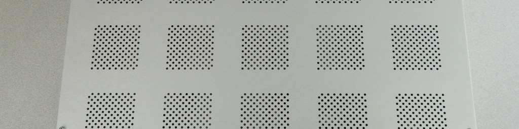
Antenna Distribution System - FCC ID S85-DAS2400 - Channel D Solutions, Inc.
Click to zoom

Application Details

Equipment Class
DTS - Digital Transmission System
Date of Grant
Jan 14, 2015
Application Purpose
Original Equipment
Date of Application
Jan 14, 2015
Equipment Note
Antenna Distribution System
Frequency Range
2402.61120000 - 2480.02560000
Company
Channel D Solutions, Inc.
Country
United States

Documents & Files

Select a file to view

Users Manual

↗

Cover Letter(s)

↗
↗
↗
↗
↗
↗

External Photos

↗

ID Label/Location Info

↗

Internal Photos

↗

RF Exposure Info

↗

Test Report

↗

Test Setup Photos

↗

Document Text

Text extracted from the exhibit documents filed with the FCC. Open a document above to read the original.

Users Manual

5015 B.U. Bowman Drive Buford, GA 30518 USA Voice: 770-831-8048 Fax: 770-831-8598 Certification Exhibit FCC ID: S85-DAS2400 IC: 10899A-DAS2400 FCC Rule Part: 15.247 IC Radio Standards Specification: RSS-210 ACS Project Number: 14-0393 Manufacturer: Channel D Solutions, Inc. Model: DAS2400 www.channelDsolutions.com Sales - 615-323-2852Tech Support - 706-622-3589 Customer: Build Date: Serial Number: AC Power fuse– Type GMA 3A Fast Blow (Spare located in connector) Location – Integrated in AC connector AC input requirements: 85 – 250 VAC 50-60 Hz Operating Temperature Range –From -40 to +50 degrees Centigrade. RF Input Connector:RP-TNC Jack RF Output (To Antenna) Connector:RP-N Jack Warranty– One year parts and labor. Physical damage due to use/abuse is not covered under warranty. See Limited Warranty statement at the end of this manual. Customer pays shipping to Channel D Solutions. WARNING– To reduce the risk of fire or electric shock, do not expose this apparatus to rain or moisture. Do not use this apparatus near water. Do not expose the apparatus to dripping or splashing. Do not place objects filled with liquids, such as vases, on the apparatus. The DAS-2400 shall be connected to a main socket outlet having a protective grounding connection. Do not install near any heat sources such as radiators, heat registers, stoves, or other apparatus (including amplifiers) that produce heat. Do not defeat the safety purpose of the polarizing or grounding type plug. A polarized plug has two blades with one wider than the other. A grounding type plug has two blades and a third grounding prong. The wide blade or third prong is provided for your safety. When the provided plug does not fit into your outlet, consult an electrician for replacement of the obsolete outlet. Protect the power cord from being walked on or pinched, particularly at plugs, convenience receptacles, and the point of exit on the DAS-2400. Only use attachments/accessories specified by the manufacturer. Unplug this apparatus during lightning storms or when unused for long periods of time. Refer all servicing to manufacturer. Servicing is required when the apparatus has been damaged in any way, for example if the power-supply cord has been damaged, liquid has been spilled or objects have fallen into the unit, or if it has been exposed to rain, moisture, does not operate normally, or has been dropped. A/C Power Warning: Users should exercise extreme care when working with electricity. Additional care should be used when working with electricity outdoors in inclement weather. When working outdoors or near water, always connect the system into a ground-fault interrupting circuit.There are no user- serviceable parts inside the DAS-2400. Opening the case may expose dangerous electrical components, and will void the warranty. Important FCC and Safety Information I. Digital Device Statement A. The DAS-2400 been tested and found to comply with the limits for Class B digital devices, pursuant to Part 15 of the Rules and Regulations of the U.S. Federal Communications Commission (the FCC) . This product is marketed as Class B digital device. These limits are designed to provide reasonable protection against harmful interference when the equipment is operated in a commercial environment. B. This equipment generates, uses, and can radiate radio-frequency energy. If not installed and used in accordance with all instructions, it may cause harmful interference to radio communications. C. Operation of this equipment in a residential area is likely to cause harmful interference, in which case the user will be required to correct the interference at his own expense. NOTE: This equipment has been tested and found to comply with the limits for a Class B digital device, pursuant to Part 15 of the FCC Rules. These limits are designed to provide reasonable protection against harmful interference in a residential installation. This equipment generates, uses, and can radiate radio frequency energy and, if not installed and used in accordance with the instructions, may cause harmful interference to radio communications. However, there is no guarantee that interference will not occur in a particular installation. If this equipment does cause harmful interference to radio or television reception, which can be determined by turning the equipment off and on, the user is encouraged to try to correct the interference by one or more of the following measures: • Reorient or relocate the receiving antenna. • Increase the separation between the equipment and receiver. • Connect the equipment into an outlet on a circuit different from that to which the receiver is connected. • Consult the dealer or an experienced radio/TV technician for help. II. Intentional Radiator Statement A. The DAS-2400 is ONLY to be used with the modular, low-power radio transceiver module that operates pursuant to Part 15 of the FCC’s Rules. The DAS-2400 can only be operated AS A COMPLETE SYSTEM under FCCID S85-DAS2400 B. Operation is subject to the following conditions: 1. The DAS-2400 system may not cause harmful interference to other users of the radio spectrum. 2. Upon notification by a representative of the FCC that a DAS-2400 system is causing harmful interference, use of the system must be suspended. Operation must not resume until the condition causing the harmful interference has been corrected. 3. The DAS-2400 system must accept any interference received, including interference that may cause undesired operation. C. The DAS-2400 system must be used with only with the approved antennas listed below. Use of any non-approved antenna, or any modification to any part of the DAS-2400 system violates the system’s warranty, and also constitutes a violation of the FCC’s Rules and Regulations and of § 302 of the Communications Act of 1934, as amended. D. To reduce potential radio interference to other users, the antenna type and its gain should be so chosen that the equivalent isotropically radiat…

Text truncated - open the document above for the full version.

Cover Letter(s)

February 26, 2013 Federal Communications Commission Equipment Authorization Branch 7435 Oakland Mills Road Columbia, MD 21046 Dear Sir or Madam: I hereby appoint Sam Wismer at Advanced Compliance Solutions, Inc. to act as our agent in the preparation of an application for equipment authorization of FCC ID: S85- DAS900 to the FCC Rules and Regulations. I certify that all exhibits contained within this filing properly describe the device or system for which authorization is sought. I further certify that appropriate arrangements have been made to assure that production units of this equipment bearing the name and FCC IDENTIFIER listed in this application will continue to comply with the Commission's requirements. I further certify by signature below that no party (per 47 CFR 1.2002(b)) to the application is subject to a denial of Federal benefits, including FCC benefits, pursuant to Section 5301 of the Anti-Drug Abuse Act of 1988, 21 U.S.C. 853(a). This appointment also includes the authority to complete FCC Form 731 on our behalf and sign the application as an authorized agent. Sincerely, W. Michael Porter W. Michael PorterW. Michael Porter W. Michael Porter W. Michael Porter President Channel D Solutions, Inc. P.O. Box 1073 Brentwood TN 37024 DAS DAS2400 October 3, 2014

Cover Letter(s)

CONFIDENTIALITY REQUEST Federal Communications CommissionDate: October 1, 2014 Equipment Authorization Branch 7435 Oakland Mills Road Columbia, MD 21046 Gentlemen: Channel D Solutions, Inc., respectfully requests confidentiality of certain materials provided with the submission of the DAS-2400 under FCC ID: S85-DAS2400 in accordance with 47 CFR 0.457(d) and 47 CFR 0.459. The confidentiality request applies to the Block Diagram and System Theory contained in this filing and included in the following files. 14-0393 – System Block Diagram.pdf 14-0393 – Theory of Operation.pdf The DAS-2400 has been developed at considerable effort and expense by Channel D Solutions, Inc. These items are considered as Trade Secrets and therefore public access to the proprietary material could possibly result in duplication of equipment that could severely damage the company's business advantage. I appreciate your assistance in this matter. Sincerely, W. Michael Porter PresidentOctober 2, 2014 Channel D Solutions, Inc. P.O. Box 1073 Brentwood TN 37024

Cover Letter(s)

5015 B. U. Bowman Dr. Buford, GA 30518 November 24, 2014 ACS TCB 5015 B.U. Bowman Drive Buford, GA 30518 Re: FCC ID: S85-DAS2400 To Whom It May Concern: The following application is submitted on behalf of our client, Channel D Solutions, Inc., for evaluation of their model DAS2400 for certification under FCC Part 15.247. The DAS2400 system provides wireless communications through the use of a 2402.6 – 2480.0 MHz frequency-hopping-spread-spectrum RF module, and transmits a digitally-encoded signal. It is used to expand communications coverage into areas that cannot be covered by a single antenna. The complete system is designed for and sold only to commercial end-users, and is not available to the general public. The DAS2400 was tested in full to the requirements of the aforementioned rules and was found to be in compliance. Sincerely, Sam Wismer Vice President, Technology Advanced Compliance Solutions, Inc.

Cover Letter(s)

October 1, 2014 DAS-2400 Module Certification To Whom It May Concern: Regarding Part 15 Unlicensed Modular Transmitter Approval, the following requirements called out in Part 15.212(a)(1) are observed: 1. The DAS-2400 has its own RF shielding. 2. The DAS-2400 modular transmitter has buffered modulation/data inputs to ensure that the module will comply with Part 15 requirements under conditions of excessive data rates or over-modulation. 3. The DAS-2400 employs on board power supply regulation. 4. The DAS-2400 employs a MMCX connector on the module, qualifying as a unique antenna coupler. 5. The DAS-2400 was tested in a stand-alone configuration. 6. The DAS-2400 has a permanently affixed label with the FCC ID: S85-DAS2400. 7. An instruction manual is provided with the system authorized under FCC ID: S85-DAS2400, detailing proper installation and usage. 8. The DAS-2400 complies with RF exposure requirements at a distance of 20 cm from the intentional radiator. J. Michael Motes Chief Engineer Channel D Solutions, Inc. P.O. Box 1073 Brentwood, TN 37024 Channel D Solutions, Inc. P.O. Box 1073 Brentwood TN 37024

Cover Letter(s)

Advanced Compliance Solutions – 5015 B.U. Bowman Drive, Buford, GA 30518 Phone: (770) 831-8048 Fax: (770) 831-8598 December 1, 2014 Federal Communications Commission Equipment Authorization Branch 7435 Oakland Mills Road Columbia, MD 21046 Gentlemen: Channel D Solutions, Inc. respectfully requests confidentiality of certain materials provided with the submission of the DAS2400 under FCC ID: S85-DAS2400 in accordance with 47 CFR 0.457(d) and 47 CFR 0.459. The following documents have been provided by a third party and require confidential treatment: 14-0393 – Schematics – Third Party – L-com.pdf 14-0393 – System Block Diagram – Third Party – L-com.pdf 14-0393 – Theory of Operation – Third Party – L-com.pdf The DAS2400 has been developed at considerable effort and expense by S85-DAS2400. These items are considered as Trade Secrets and therefore public access to the proprietary material could possibly result in duplication of equipment that could severely damage the company’s business advantage. I appreciate your assistance in this matter. Sincerely, Sam Wismer Vice President, Technology Agent

Cover Letter(s)

Advanced Compliance Solutions – 5015 B.U. Bowman Drive, Buford, GA 30518 Phone: (770) 831-8048 Fax: (770) 831-8598 December 1, 2014 Federal Communications Commission Equipment Authorization Branch 7435 Oakland Mills Road Columbia, MD 21046 Gentlemen: Channel D Solutions, Inc. respectfully requests confidentiality of certain materials provided with the submission of the DAS2400 under FCC ID: S85-DAS2400 in accordance with 47 CFR 0.457(d) and 47 CFR 0.459. The following documents have been provided by a third party and require confidential treatment: 14-0393 – Schematics – Third Party – RFM.pdf 14-0393 – System Block Diagram – Third Party – RFM.pdf 14-0393 – Theory of Operation – Third Party – RFM.pdf The DAS2400 has been developed at considerable effort and expense by Channel D Solutions, Inc.. These items are considered as Trade Secrets and therefore public access to the proprietary material could possibly result in duplication of equipment that could severely damage the company’s business advantage. I appreciate your assistance in this matter. Sincerely, Sam Wismer Vice President, Technology Agent

External Photos

5015 B.U. Bowman Drive Buford, GA 30518 USA Voice: 770-831-8048 Fax: 770-831-8598 Certification Exhibit FCC ID: S85-DAS2400 IC: 10899A-DAS2400 FCC Rule Part: 15.247 IC Radio Standards Specification: RSS-210 ACS Project Number: 14-0393 Manufacturer: Channel D Solutions, Inc. Model: DAS2400 Model: DAS2400FCC ID: S85-DAS2400IC: 10899A-DAS2400 ACS Project: 14-0393Advanced Compliance SolutionsPage 2 Figure 1: External Photo Figure 2: External Photo Model: DAS2400FCC ID: S85-DAS2400IC: 10899A-DAS2400 ACS Project: 14-0393Advanced Compliance SolutionsPage 3 Figure 3: External Photo Figure 4: External Photo Model: DAS2400FCC ID: S85-DAS2400IC: 10899A-DAS2400 ACS Project: 14-0393Advanced Compliance SolutionsPage 4 Figure 5: External Photo Figure 6: External Photo Model: DAS2400FCC ID: S85-DAS2400IC: 10899A-DAS2400 ACS Project: 14-0393Advanced Compliance SolutionsPage 5 Figure 7: External Photo – RF Module Figure 8: External Photo – RF Module Model: DAS2400FCC ID: S85-DAS2400IC: 10899A-DAS2400 ACS Project: 14-0393Advanced Compliance SolutionsPage 6 Figure 9: External Photo – RF Module Figure 10: External Photo – RF Module Model: DAS2400FCC ID: S85-DAS2400IC: 10899A-DAS2400 ACS Project: 14-0393Advanced Compliance SolutionsPage 7 Figure 11: External Photo – RF Module Figure 12: External Photo – RF Module

ID Label/Location Info

5015 B.U. Bowman Drive Buford, GA 30518 USA Voice: 770-831-8048 Fax: 770-831-8598 Certification Exhibit FCC ID: S85-DAS2400 IC: 10899A-DAS2400 FCC Rule Part: 15.247 IC Radio Standards Specification: RSS-210 ACS Project Number: 14-0393 Manufacturer: Channel D Solutions, Inc. Model: DAS2400 Model: DAS2400FCC ID: S85-DAS2400IC: 10899A-DAS2400 ACS Project: 14-0393Advanced Compliance SolutionsPage 2 Figure 1: Sample Label – Label affixed to right side of DAS2400 antenna distribution chassis Figure 2: Sample Label Location - DAS2400 antenna distribution chassis Model: DAS2400FCC ID: S85-DAS2400IC: 10899A-DAS2400 ACS Project: 14-0393Advanced Compliance SolutionsPage 3 Figure 3: Sample Label – Label affixed to the DAS2400 RF Module Figure 4: Sample Label Location - DAS2400 RF Module Model: DAS2400FCC ID: S85-DAS2400IC: 10899A-DAS2400 ACS Project: 14-0393Advanced Compliance SolutionsPage 4 Figure 5: Sample Label – Label affixed to host equipment containing DAS2400 RF Module

Internal Photos

5015 B.U. Bowman Drive Buford, GA 30518 USA Voice: 770-831-8048 Fax: 770-831-8598 Certification Exhibit FCC ID: S85-DAS2400 IC: 10899A-DAS2400 FCC Rule Part: 15.247 IC Radio Standards Specification: RSS-210 ACS Project Number: 14-0393 Manufacturer: Channel D Solutions, Inc. Model: DAS2400 Model: DAS2400FCC ID: S85-DAS2400IC: 10899A-DAS2400 ACS Project: 14-0393Advanced Compliance SolutionsPage 2 Figure 1: Internal Photo – DAS2400 Interior View Figure 2: Internal Photo – Top View of RF Amplifier Model: DAS2400FCC ID: S85-DAS2400IC: 10899A-DAS2400 ACS Project: 14-0393Advanced Compliance SolutionsPage 3 Figure 3: Internal Photo – Side View of RF Amplifier Figure 4: Internal Photo – RF Amplifier Board installed in Amp Chassis Model: DAS2400FCC ID: S85-DAS2400IC: 10899A-DAS2400 ACS Project: 14-0393Advanced Compliance SolutionsPage 4 Figure 5: Internal Photo – RF Module installed with Bottom Shield, Top Shield Removed Model: DAS2400FCC ID: S85-DAS2400IC: 10899A-DAS2400 ACS Project: 14-0393Advanced Compliance SolutionsPage 5 Figure 6: Internal Photo – Top of RF Module Figure 7: Internal Photo – Bottom of RF Module Model: DAS2400FCC ID: S85-DAS2400IC: 10899A-DAS2400 ACS Project: 14-0393Advanced Compliance SolutionsPage 6 Figure 8: Internal Photo – Top of Amplifier Board Figure 9: Internal Photo – Bottom of Amplifier Board

RF Exposure Info

Certification Exhibit FCC ID: S85-DAS2400 IC: 10899A-DAS2400 FCC Rule Part: 15.247 IC Radio Standards Specification: RSS-210 ACS Project Number: 14-0393 Manufacturer: Channel D Solutions, Inc. Model: DAS2400 RF Exposure 5015 B.U. Bowman Drive Buford, GA 30518 USA Voice: 770-831-8048 Fax: 770-831-8598 Model: DAS2400 FCC ID: S85-DAS2400 IC: 10899A-DAS2400 General Information: Applicant: Channel D Solutions, Inc. Device Category: Mobile Environment: General Population/Uncontrolled Exposure Technical Information: Antenna Type / Gain: Channel D Solutions part number 479980, 2 dBi omnidirectional Channel D Solutions part number 385564, 3 dBi omnidirectional Max Directional Gain: 3 dBi + 10*Log(8) = 12 dBi Maximum Transmitter Conducted Power: 17.55 dBm, 56.84 mW Maximum System EIRP: 29.55 dBm, 901.57 mW Exposure Conditions: Greater than 20 centimeters Note: The directional gain was calculated based on FCC KDB 662911 D01 Multiple Transmitter Output v01r02 as worst case, assuming (8) correlated outputs. However, in a normal operating configuration the antennas cannot be installed such that the patterns overlap. As worst case, even though not achievable for system operation, the directional gain calculation and maximum EIRP calculation were based on collocated correlated transmissions. MPE Calculation The Power Density (mW/cm 2 ) is calculated as follows: S = 2 4R PG π Where: S = power density (in appropriate units, e.g. mW/cm2) P = power input to the antenna (in appropriate units, e.g., mW) G = power gain of the antenna in the direction of interest relative to an isotropic radiator R = distance to the center of radiation of the antenna (appropriate units, e.g., cm) MPE Calculator for Mobile Equipment Limits for General Population/Uncontrolled Exposure* 2480.025617.551.0056.891215.849 200.179 Power De n si ty (mW/cm^2) Distance (cm) Transmit Frequency (MHz) Radio Power (dBm) Power Density Limit (mW/Cm2) Radio Power (mW) Antenna Gain (dBi) Antenna Gain (mW e q.) Installation Guidelines The installation manual should contain text similar to the following advising how to install the equipment to maintain compliance with the FCC RF exposure requirements: RF Exposure In accordance with FCC requirements of human exposure to radio frequency fields, the radiating element shall be installed such that a minimum separation distance of 20 centimeters will be maintained. Conclusion This device complies with the MPE requirements by providing adequate separation between the device, any radiating structure and the general population. ACS Project: 14-0393 Advanced Compliance Solutions Page 2

Test Report

5015 B.U. Bowman Drive Buford, GA 30518 USA Voice: 770-831-8048 Fax: 770-831-8598 Certification Test Report FCC ID: S85-DAS2400 IC: 10899A-DAS2400 FCC Rule Part: 15.247 IC Radio Standards Specification: RSS-210 ACS Report Number: 14-0393.W06.1A Manufacturer: Channel D Solutions, Inc. Model: DAS2400 Test Begin Date: October 20, 2014 Test End Date: November 20, 2014 Report Issue Date: November 24, 2014 FOR THE SCOPE OF ACCREDITATION UNDER LAB Code 200612-0 This report must not be used by the client to claim product certification, approval, or endorsement by NVLAP, NIST, or any agency of the Federal Government. Reviewed by: Kirby Munroe Director, Wireless Certifications ACS, Inc. This test report shall not be reproduced except in full. This report may be reproduced in part with prior written consent of ACS, Inc. The results contained in this report are representative of the sample(s) submitted for evaluation. This report contains 26 pages 5015 B.U. Bowman Drive Buford, GA 30518 USA Voice: 770-831-8048 Fax: 770-831-8598 TABLE OF CONTENTS 1GENERAL .............................................................................................................................................. 3 1.1PURPOSE............................................................................................................................................ 3 1.2PRODUCTDESCRIPTION..................................................................................................................... 3 1.3TESTMETHODOLOGY ANDCONSIDERATIONS................................................................................... 3 2TEST FACILITIES ................................................................................................................................ 4 2.1LOCATION......................................................................................................................................... 4 2.2LABORATORYACCREDITATIONS/RECOGNITIONS/CERTIFICATIONS.................................................. 4 2.3RADIATEDEMISSIONSTESTSITEDESCRIPTION................................................................................ 5 2.3.1Semi-Anechoic Chamber Test Site ........................................................................................... 5 2.3.2Open Area Tests Site (OATS) ................................................................................................... 6 2.4CONDUCTEDEMISSIONSTESTSITEDESCRIPTION............................................................................ 7 3APPLICABLE STANDARD REFERENCES ..................................................................................... 7 4LIST OF TEST EQUIPMENT.............................................................................................................. 8 5SUPPORT EQUIPMENT ...................................................................................................................... 9 6EQUIPMENT UNDER TEST SETUP BLOCK DIAGRAM ............................................................ 9 7SUMMARY OF TESTS ....................................................................................................................... 10 7.1ANTENNAREQUIREMENT–FCC15.203......................................................................................... 10 7.2POWERLINECONDUCTEDEMISSIONS–FCC15.207,IC:RSS-GEN8.8 ........................................ 10 7.2.1Measurement Procedure ........................................................................................................ 10 7.2.2Measurement Results.............................................................................................................. 10 7.36DB/99%BANDWIDTH–FCC15.247(A)(2),IC:RSS-210A8.2(A) ............................................. 12 7.3.1Measurement Procedure ........................................................................................................ 12 7.3.2Measurement Results.............................................................................................................. 12 7.4FUNDAMENTALEMISSIONOUTPUTPOWER–FCC15.247(B)(3),IC:RSS-210A8.4(4) ................ 14 7.4.1Measurement Procedure ........................................................................................................ 14 7.4.2Measurement Results.............................................................................................................. 14 7.5EMISSIONLEVELS–FCC15.247(D),15.205,15.209;ICRSS-2102.2/A8.5,RSS-GEN8.9 .......... 15 7.5.1Emissions into Non-restricted Frequency Bands ................................................................... 15 7.5.1.1Measurement Procedure .................................................................................................................... 15 7.5.1.2Measurement Results ......................................................................................................................... 15 7.5.2Emissions into Restricted Frequency Bands .......................................................................... 18 7.5.2.1Measurement Procedure .................................................................................................................... 18 7.5.2.2Duty Cycle Correction ....................................................................................................................... 18 7.5.2.3Measurement Results ......................................................................................................................... 18 7.5.2.4Sample Calculation: ........................................................................................................................... 20 7.6MAXIMUMPOWERSPECTRALDENSITY IN THEFUNDAMENTALEMISSION–FCC15.247(E)IC: RSS-210A8.2(B) ........................................................................................................................................ 21 7.6.1Measurement Procedure .............................................................................................…

Text truncated - open the document above for the full version.

Test Setup Photos

5015 B.U. Bowman Drive Buford, GA 30518 USA Voice: 770-831-8048 Fax: 770-831-8598 Certification Exhibit FCC ID: S85-DAS2400 IC: 10899A-DAS2400 FCC Rule Part: 15.247 IC Radio Standards Specification: RSS-210 ACS Project Number: 14-0393 Manufacturer: Channel D Solutions, Inc. Model: DAS2400 Model: DAS2400FCC ID: S85-DAS2400IC: 10899A-DAS2400 ACS Project: 14-0393Advanced Compliance SolutionsPage 2 Figure 1: Radiated Emissions – Whip Antenna XPOS Figure 2: Radiated Emissions – Whip Antenna XPOS Model: DAS2400FCC ID: S85-DAS2400IC: 10899A-DAS2400 ACS Project: 14-0393Advanced Compliance SolutionsPage 3 Figure 3: Radiated Emissions – Whip Antenna YPOS Figure 4: Radiated Emissions – Whip Antenna YPOS Model: DAS2400FCC ID: S85-DAS2400IC: 10899A-DAS2400 ACS Project: 14-0393Advanced Compliance SolutionsPage 4 Figure 5: Radiated Emissions – Whip Antenna ZPOS Figure 6: Radiated Emissions – Whip Antenna ZPOS Model: DAS2400FCC ID: S85-DAS2400IC: 10899A-DAS2400 ACS Project: 14-0393Advanced Compliance SolutionsPage 5 Figure 7: Radiated Emissions – Ceiling Antenna XPOS Figure 8: Radiated Emissions – Ceiling Antenna XPOS Model: DAS2400FCC ID: S85-DAS2400IC: 10899A-DAS2400 ACS Project: 14-0393Advanced Compliance SolutionsPage 6 Figure 9: Conducted Emissions – DAS2400 Figure 10: Conducted Emissions – DAS2400 Model: DAS2400FCC ID: S85-DAS2400IC: 10899A-DAS2400 ACS Project: 14-0393Advanced Compliance SolutionsPage 7 Figure 11: Conducted Emissions – DAS2400 Supply Figure 12: Conducted Emissions – DAS2400 Supply

Contact Information

Applicant

W Michael Porter(President)
[email protected](615)480-6965Fax: (615)371-5005

Test Firm

Advanced Compliance Solutions, Inc.Randy Abernathy
[email protected]770-831-8048Fax: 770-831-8598

Technical Specifications

#Rule PartsFrequency RangePower Output
115C2.40 GHz - 2.48 GHz57.00 mW
Modular Type
Single Modular Approval
Confidentiality
Long Term
Grant Notes
Modular Approval. Power Output listed is conducted. Approval is limited to OEM installation only. OEM integrators must be provided with antenna installation instructions. OEM integrators and end-users must be provided with transmitter operation conditions for satisfying RF exposure compliance. This grant is valid only when the device is sold to OEM integrators and the OEM integrators are instructed to ensure that the end user has no manual instructions to remove or install the device. This device must transmit with a source-based time-averaging duty factor not exceeding 0.833%. The antenna(s) used for this transmitter must be installed to provide a separation distance of at least 20 cm from all persons and must not be co-located or operating in conjunction with any other antenna or transmitter. Device must be marketed and operated as a complete system.

Other Applications from Channel D Solutions, Inc.

Antenna Distribution System - FCC ID S85-DAS900 - Channel D Solutions, Inc.
S85-DAS900

Antenna Distribution System

Mar 11, 2013

Equipment Class

DSS - Part 15 Spread Spectrum Transmitter