S9E-RGTSC3WNRanger/TSC3
Trimble Inc.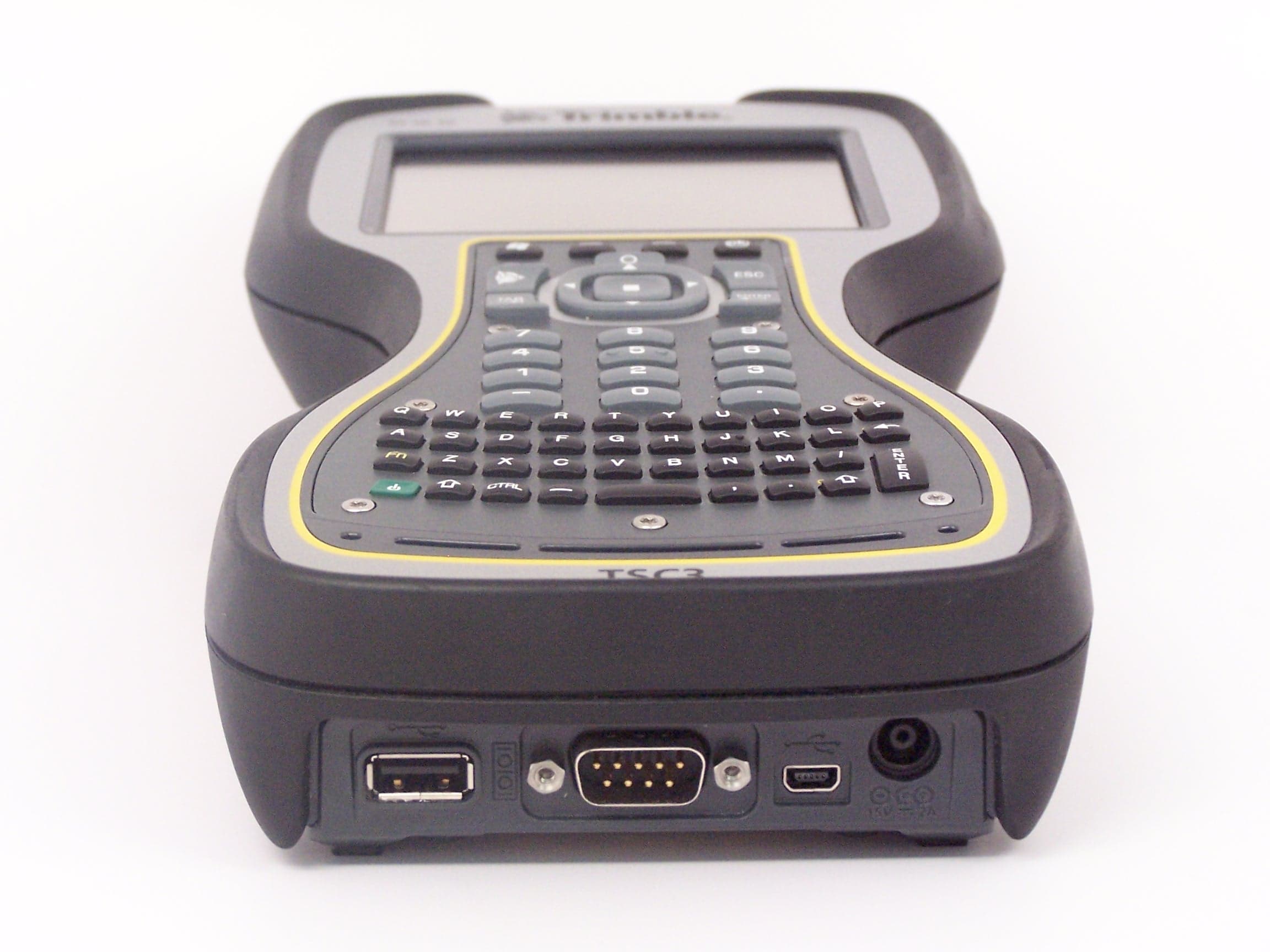
Click to zoom
Application Details
- Equipment Class
- PCB - PCS Licensed Transmitter
- Date of Grant
- Nov 04, 2010
- Application Purpose
- Original Equipment
- Date of Application
- Nov 01, 2010
- Equipment Note
- Ranger/TSC3
- Frequency Range
- 1852.40000000 - 1907.60000000
- Company
- Trimble Inc.
- Country
- United States
Documents & Files
Document Text
Text extracted from the exhibit documents filed with the FCC. Open a document above to read the original.
Users Manual
GETTING STARTED GUIDE Ranger ® Series data collector September 2010 2 Limited Warranty & Liability Limitations This unit and battery are limited warranted against defects in materials and workmanship for twelve (12) months from the original date of purchase. All other accessories and peripherals are limited warranted against defects in materials and workmanship for ninety (90) days from the original date of purchase. If notice is received of such defects during the limited warranty period, the proven defective product(s) will either be repaired or replaced, at the manufacturer’s option. Replacement products may be either new or like new. The manufacturer does not warrant that the operation of the products will be uninterrupted or error free. If the product is not, within a reasonable time, repaired or replaced to a condition as limited warranted, the customer will be entitled to a refund of the purchase price upon prompt return of the product. Limited warranty does not apply to defects resulting from (a) improper or inadequate maintenance or calibration, (b) software, interfacing, parts, or supplies not supplied by manufacturer, (c) unauthorized modification, or misuse, (d) operation outside of the published environmental specifications for the product, or (e) physical damage due to external causes, including accident, abuse, misuse or problems with electrical power. Water damage caused by improper installation of the accessories and service parts is not covered by warranty. Removal of the back case or X-bay lid voids the limited warranty. There are important seals that will break and the unit will no longer be waterproof. To the extent allowed by local law, the above limited warranties are exclusive and no other warranty or condition, whether written or oral, is expressed or implied, specifically disclaiming any implied warranties or conditions of merchantability, satisfactory quality, and fitness for a particular purpose. To the extent allowed by local law, the remedies in this limited warranty statement are the customer’s sole and exclusive remedies. Except as indicated above, in no event will the manufacturer or its suppliers be liable for loss of data or for direct, special, incidental, consequential (including lost profit or data), or other damage, whether based in contract, tort, or otherwise. 3 Contents Welcome......................................................................................3 Device Hardware.........................................................................4 Unit Setup....................................................................................6 Working with the Unit and the Battery......................................10 Status indicators.........................................................................15 Settings on your Unit.................................................................16 Communication..........................................................................19 Connecting to a PC....................................................................19 Working with Bluetooth............................................................20 Working with Wi-Fi (Wireless Lan, WLAN or 802.11)...........22 Working with the Camera..........................................................24 Working with the Barcode Scanner...........................................27 Working with the GPS...............................................................28 SatViewer..................................................................................29 Working with the Wireless WAN..............................................30 Troubleshooting.........................................................................34 Caring for your Unit..................................................................35 Environmental Considerations...................................................36 Environmental Specifications....................................................37 Hardware Specifications............................................................37 Regulatory Information.............................................................38 Declaration of Conformity.........................................................39 Safe Use of your Unit................................................................40 Appendix A................................................................................43 Using SatViewer........................................................................43 Welcome Congratulations on your purchase of the most powerful and advanced handheld computer available on the market today. Its rugged design allows you to work in harsh outdoor environments. You can operate your unit in blazing heat, subzero cold, driving rain or dusty job sites – places you could not take a consumer-grade handheld computer. NOTE: Not all the features discussed in this manual will apply to every unit, as some of the features are offered as options. If the feature described does not apply to your unit, please disregard that section. 4 Device Hardware Front View Back View NOTE: Some features are offered as options and may not apply to your unit. Be sure to read the warranty and safety information in this manual prior to using your unit. Notification LEDs Enter Power Battery Door Latch (under hand strap) Battery Door Hand Strap Stylus 2.4 GHz Antenna (if present) Navigation Pad Enter Dual LED Camera Flash Qwerty Keypad Camera 5 Top View Bottom View I/O The I/O has a mini-USB client (to connect to Microsoft Windows Mobile Device Center used on Microsoft Windows Vista ® and Windows 7 ® or connect to Microsoft ActiveSync ® used on Microsoft Windows XP ® ), a USB host port (to connect to USB client devices) and a DB9 RS-232 connector (for use with serial devices). NOTE: COM1 is always reserved in software for the 9-pin port. Many USB host peripheral devices supported by personal computers (Microsoft Windows XP, Microsoft Vista, Microsoft Windows 7, et…
Text truncated - open the document above for the full version.
Cover Letter(s)
Northwest EMC TCB Compliance Opinion Rev. 12/08/09 TRPO0055 Information about the Applicant Grantee (Company Name) Trimble Navigation Limited FCC Contact Person Bob Grant Address 345 SW Avery Ave City, State, Zip Corvallis, OR 97333 Job Number TRPO0055 Model Ranger/TSC3WN FCC ID S9E-RGTSC3WN Agent Approval Type Original Equipment Class PCB - PCS Licensed Transmitter Rule Part 22H and 24E Overview This application is for an original approval of a WWAN cellular modem radio FCC ID: S9E- RGTSC3WN. A limited modular approval is requested for the radio installed in the Trimble Handheld Computer, model Ranger/TSC3. The Ranger \TSC3 will also contain FCC ID: S9E- RGTSC3BW and FCC ID: S9E-RNGR2410. Test reports and RF exposure reports have been submitted in support of this application. Confidentiality requested for allowed files. Request is properly addressed and referenced. A letter listing the applicable modular requirements was submitted. Recommendation All items have been resolved and completed to my satisfaction; therefore I recommend this application for approval. Signature 10/27/2010 Dave Tolman, TCB Committee
Cover Letter(s)
Trimble Navigation Limited MCS 345 SW Avery Corvallis, OR 97333 September 15, 2010 To whom it may concern, Trimble Navigation Limited MCS is submitting this application for an Original certification for FCC ID: S9E-RGTSC3WN. It is a WWAN module. It is seeking limited modular approval for co-location with other radios in the Trimble Handheld computer Model Ranger/TSC3. The Ranger/TSC3 also contains a combination Wi-Fi / Bluetooth radio module (FCC ID: S9E-RGTSC3BW) and a FHSS module (FCC ID: S9E-RNGR2410). This application contains an EMC test report for the WWAN module and RF safety information for the co-located radios. All of the modules are installed by the client and are not user accessible. The modules will not be sold individually. Your attention to this matter is greatly appreciated and please contact me if you have any questions. Best regards, Bob Grant Regulatory Engineer Trimble Navigation [email protected]
Cover Letter(s)
Trimble Navigation Limited MCS 345 SW Avery Corvallis, OR 97333 September 15, 2010 Dear Application Examiner: We, Trimble Navigation Limited, are seeking limited modular approval for Ranger/TSC3 (FCC ID S9E-RGTSC3WN). The radio meets the requirements for modular approval as detailed in FCC 15.212. Compliance to each of the requirements is described below: 1. “The modular transmitter must have its own RF shielding.” The radio portion of the module is contained in its own RF shielding. The shielding is installed at the factory. Please see the Internal Photos exhibit. 2. “The modular transmitter must have buffered modulation/data inputs.” The EUT has buffered data inputs to insure compliance with Part 15 requirements under conditions of excessive data rates or over-modulation. Please see the Schematics exhibit. 3. “The modular transmitter must have its own power supply regulation.” The EUT has its own power supply regulation to insure compliance with Part 15 requirements regardless of the quality or level of external DC supplying the module from the host unit. Please see Schematics exhibit. Also, the technical report exhibit contains AC power line conducted emissions data taken with the EUT powered from a linear power supply that contains no EMC suppression components. 4. “The modular transmitter must comply with the antenna requirements of Section 15.203 and 15.204(c).” The EUT meets the FCC antenna requirements. Please see Antenna information exhibit and internal photos exhibit. 5. “The modular transmitter must be tested in a stand-alone configuration.” The EUT was tested in a stand-alone configuration. The module was greater than 10 cm from the host device. Please see test setup photos exhibit and technical report exhibit. 6. “The modular transmitter must be labeled with its own FCC ID number.” The Although the host device is labeled with “Contains FCC ID: S9ERGTSC3WN” The module itself is not labeled with its own FCC ID number. The module will always be installed by Trimble in their host device. Please see FCC ID label & location exhibit. 7. “The modular transmitter must comply with any specific rule or operating requirements applicable to the transmitter and the manufacturer must provide adequate instructions along with the module to explain any such requirements.” The EUT is compliant with all applicable FCC rules. Detail instructions for maintaining compliance are given in the User Manual. 8. “The modular transmitter must comply with any applicable RF exposure requirements.” The EUT is compliant with all applicable RF exposure requirements. Please see RF Exposure Exhibit. Please contact me if you have additional questions. Your attention to this matter is greatly appreciated. Best regards, Bob Grant Regulatory Engineer Trimble Navigation [email protected]
Internal Photos
Cell Radio Cell Antenna WiFi Bluetooth Radio WiFi Bluetooth Antenna Cirronet Radio Cirronet Antenna
Operational Description
PRODUCT: CELLULAR ETHERTRONICS 9605 Scranton Road, Suite 300 | San Diego, CA 92121 - USA | www.ethertronics.com tel +(1) 858.550.3820 | fax +(1) 858.550.3821 | contact: [email protected] TECHNOLOGY ADVANTAGES KEY BENEFITS Part No. P522303 Stays in Tune IMD antenna technology provides superior RF field containment, resulting in less interaction with surrounding components. Ethertronics IMD antennas resist de-tuning; providing a robust radio link regardless of the usage position. Prestta TM Standard Penta-Band Cellular Embedded Antenna 850/900/1800/1900/2100 MHz SERVICE AND SUPPORT Extensive RF Experience • Our Prestta antennas are supported by documentation, and when needed, by the expertise of RF engineers who have integrated hundreds of antenna designs into wireless devices. Global Operations & Design Support • Ethertronics’ global operations supports an integrated network of design centers that can take projects from concept to production. Ethertronics’ Prestta series of Isolated Magnetic Di- pole™ (IMD) embedded antennas address the chal- lenges facing today’s product designers. IMD’s high performance and isolation characteristics offer bet- ter connectivity and minimal interference. Prestta antennas can be used in a variety of applications in- cluding: • M2M • Automotive • Automatic Meter Reading • Healthcare • Point of Sale • Tracking END USER ADVANTAGES Unique Form Factors Support Advanced Industrial Designs • Smaller, more efficient IMD embedded antennas break through restrictive design rules and provide new free- dom in component placement. Superior Range • Better antenna function means longer range and greater sensitivity to critically precise signals— delivering greater customer satisfaction while building brand loyalty. DESIGN ADVANTAGES Reduced Costs and Time-to-Market • Standard antenna eliminates design fees and cycle time associated with a custom solution; getting prod- ucts to market faster. Greater Flexibility with Unique Form Factors • Ethertronics’ IMD technology helps you deliver more advanced ergonomic designs without adverse impact on product performance. • SMD mountable design enables faster and lower cost manufacturing. RoHS Compliant • Ethertronics’ antennas are fully compliant with the European RoHS Directive 2002/95/EC. Prestta antennas use patented IMD technology in a stamped metal configuration to provide high performance. IMD antennas requires a smaller design keep-out area, carry lower program development risk which yields a quicker time-to-market, without sacrificing RF performance. Example: Ethertronics’ Penta-Band Internal (Embedded) Antenna Specifications. Below are the typical specs for a Penta-Band application. PRODUCT: Cellular Electrical Specifications Typical Characteristics Measurements taken with a match- ing circuit on a 50 x 110 mm ground plane. Cellular Antenna 824-849, 869-894 880-915, 925-960 1710-1785, 1805-1880 1850-1910, 1930-1990 1920– 1980, 2110-2170 Peak Gain 1.4 dBi 1.2 dBi 2.7 dBi 2.6 dBi 2.8 dBi Average Efficiency 62% VSWR Match 2.5:1 max Feed Point Impedance 50 ohms unbalanced (other if required) Power Handling 2 Watt cw Polarization Linear 66% Maximum Dimensions 42.5 x 12.7 x 8.1 mm Mechanical Mounting Metal on plastic carrier. Antenna Assembly is SMD attached to main PCB. RF Mounting RF and Ground feed pads are SMD attached to main PCB. Mechanical Specifications Typical Efficiency Typical Return Loss PRODUCT: Cellular © 2010 Ethertronics. All rights reserved. Ethertronics, the Ethertronics logo, shaping antenna technology, Prestta, Isolated Magnetic Dipole and the iMD logo are trademarks of Ethertronics. All other trademarks are the property of their respective owners. Specifications subject to change and are dependent upon actual implementation. Cell 04-13-10 Ethertronics’ Test Board PCB: 50x110mm Antenna Radiation Patterns Typical Performance +x +y +z(up) +x -z (up) +y -z +y +x (up) +x +y +z(up) +x -z (up) +y -z +y +x (up) +x +y +z(up) +x -z (up) +y -z +y +x (up) +x +y +z(up) +x -z (up) +y -z +y +x (up) +x -z (up) +y -z +y +x (up) .17 - 30.64 1.81 - 13.82 -.63 - 31.98 1.35 - 14.97 .79 - 16.51 50x110mm z (up) y (back) x (right) +x +y +z(up)
RF Exposure Info
NORTHWEST EMC OVERVIEW COMPLIANCE WITH 2.1091 All other mobile and unlicensed transmitting devices are categorically excluded from routine environmental evaluation for RF exposure prior to equipment authorization or use, except as specified in §§1.1307(c) and 1.1307(d) of this chapter. Applications for equipment authorization of mobile and unlicensed transmitting devices subject to routine environmental evaluation must contain a statement confirming compliance with the limits specified in paragraph (d) of this section as part of their application.” “Mobile devices that operate in the Cellular Radiotelephone Service, the Personal Communications Services, the Satellite Communications Services, the General Wireless Communications Service, the Wireless Communications Service, the Maritime Services and the Specialized Mobile Radio Service authorized under subpart H of part 22 of this chapter, parts 24, 25, 26 and 27 of this chapter, part 80 of this chapter (ship earth stations devices only) and part 90 of this chapter are subject to routine environmental evaluation for RF exposure prior to equipment authorization or use if they operate at frequencies of 1.5 GHz or below and their effective radiated power (ERP) is 1.5 watts or more, or if they operate at frequencies above 1.5 GHz and their ERP is 3 watts or more. Unlicensed personal communications service devices, unlicensed millimeter wave devices and unlicensed NII devices authorized under §§15.253, 15.255, and 15.257, and subparts D and E of part 15 of this chapter are also subject to routine environmental evaluation for RF exposure prior to equipment authorization or use if their ERP is 3 watts or more or if they meet the definition of a portable device as specified in §2.1093(b) requiring evaluation under the provisions of that section. The EUT will only be used with a separation distance of 20 centimeters or greater between the antenna and the body of the user or nearb y persons and can therefore be considered a mobile transmitter per 47 CFR 2.1091(b). Per 47 CFR Maximum Permissible Exposure (MPE) XMit 2008.12.29 2 **4 * R GP S Human exposure to RF emissions from mobile devices (47 CFR §2.1091) may be evaluated based on the MPE limits adopted by the FCC for electric and magnetic field strength and/or power density, as appropriate, since exposures are assumed to occur at distances of 20 cm or more from persons. ANSI C95.1-1992 specifies a minimum separation distance of 20 cm for performing reliable field measurements to determine adherence to MPE limits. If the minimum separation distance between a transmitter and nearby persons is more than 20 cm under normal operating conditions, compliance with MPE limits may be determined at such distance from the transmitter. When applicable, operation instructions and prominent warning labels may be used to alert the exposed persons to maintain a specified distance from the transmitter or to limit their exposure durations and usage conditions to ensure compliance. If the use of warning labels on a transmitter is not effective or desirable, the alternative of performing SAR evaluation with the device at its closest range to persons under normal operating conditions may be used. The field strength and power density limits adopted by the FCC are based on whole-body averaged exposure and the assumption of RF field levels relate most accurately to estimating whole-body averaged SAR. This means some local values of exposures exceeding the stated field strength and power density limits may not necessarily imply non-compliance if the spatial average of spatially averaged RF fields over the exposed portions of a person’s body does not exceed the limits. COMPLIANCE WITH FCC KDB 447498 D01 Mobile Portable RF Exposure V04 FCC LIMITS FOR MPE Limits for General Population /Uncontrolled Expsoure: 47 CFR 1.1310 METHOD OF EVALUATION The exposure level at a 20 cm distance from the EUT’s transmitting antenna is calculated using the general equation: 1500 - 100000 f = frequency in MHz the user or nearby persons and can therefore be considered a mobile transmitter per 47 CFR 2.1091(b). Per 47 CFR 1.1310, the EUT meets the General Population / Uncontrolled exposure limits listed in Table 1. 30 30 - 300 * = Plane-wave equivalent power density 30 0.3 - 1.34 1 300 - 1500f/1500 1.34 - 30824/f 1.63*(100) 2.19/f*(180/f 2 ) 27.50.0730.2 Power Density 30 30 30 (MHz)(V/m)(A/m)(mW/cm 2 ) 614 The cellular, WiFi / Bluetooth, and Cirronet radio transceivers are mobile transmitters and are greater than 5 cm from each other and all other simultaneous transmitting antennas. "KDB 447498 D01 Mobile Portable RF Exposure v04" provides the procedures, requirements, and authorization policies for mobile and portable devices. Item #8 best fits the exosure condition described in this report. Since these mobile devices are categorically excluded from routine evaluation; per footnotes 1 and 32 of KDB 447498, simple calculations may be used to estimate the power density to demonstrate compliance with 47 CFR 1.1310 requirements. The attached estimate shows MPE limits are met for simultaneous transmission at a 20 cm boundary. Averaging Time (minutes) Frequency RangeStrength g Strength 2 **4 * R GP S Human exposure to RF emissions from mobile devices (47 CFR §2.1091) may be evaluated based on the MPE limits adopted by the FCC for electric and magnetic field strength and/or power density, as appropriate, since exposures are assumed to occur at distances of 20 cm or more from persons. ANSI C95.1-1992 specifies a minimum separation distance of 20 cm for performing reliable field measurements to determine adherence to MPE limits. If the minimum separation distance between a transmitter and nearby persons is more than 20 cm under normal operating conditions, compliance with MPE limits may be determined at such distance from the transmitter. When applicable, operation instructions and prominent warning labels may be used to alert the exposed person…
Text truncated - open the document above for the full version.
Test Report
Trimble Navigation Limited Ranger/TSC3 WWAN Radio Report No. TRPO0055 Report Prepared By www.nwemc.com 1-888-EMI-CERT © 2010 Northwest EMC, Inc 22975 NW Evergreen Parkway Suite 400 Hillsboro, Oregon 97124 Certificate of Test Last Date of Test: September 2, 2010 Trimble Navigation Limited Model: Ranger/TSC3 WWAN Radio Emissions Test Description Specification Test Method Pass/Fail Out of Band Emissions FCC 22H:2009 ANSI/TIA/EIA-603-C-2004 Pass Out of Band Emissions FCC 24E:2009 ANSI/TIA/EIA-603-C-2004 Pass Effective Radiated Power (ERP) FCC 22H:2009 ANSI/TIA/EIA-603-C-2004 Pass Effective Radiated Power (EIRP) FCC 24E:2009 ANSI/TIA/EIA-603-C-2004 Pass Modifications made to the product See the Modifications section of this report Test Facility The measurement facility used to collect the data is located at: Northwest EMC, Inc. 22975 NW Evergreen Parkway, Suite 400 Hillsboro, OR 97124 Phone: (503) 844-4066 Fax: (503) 844-3826 This site has been fully described in a report filed with and accepted by the FCC (Federal Communications Commission) and Industry Canada (Site filing #2834D-2). Approved By: Don Facteau, IS Manager NVLAP Lab Code: 200630-0 This report must not be used to claim product certification, approval, or endorsement by NVLAP, NIST, or any agency of the federal government of the United States of America. Product compliance is the responsibility of the client, therefore the tests and equipment modes of operation represented in this report were agreed upon by the client, prior to testing. This Report may only be duplicated in its entirety. The results of this test pertain only to the sample(s) tested. The specific description is noted in each of the individual sections of the test report supporting this certificate of test. Northwest EMC Revision History Revision 06/29/09 Revision Number Description Date Page Number 00 None Barometric Pressure The recorded barometric pressure has been normalized to sea level. Accreditations and Authorizations FCC Accredited by NVLAP for performance of FCC radio, digital, and ISM device testing. Our Open Area Test Sites, certification chambers, and conducted measurement facilities have been fully described in reports filed with the FCC and accepted by the FCC in letters maintained in our files. Northwest EMC has been accredited by ANSI to ISO / IEC Guide 65 as a product certifier. We have been designated by the FCC as a Telecommunications Certification Body (TCB). This allows Northwest EMC to certify transmitters to FCC specifications in accordance with 47 CFR 2.960 and 2.962. NVLAP Northwest EMC, Inc. is accredited under the United States Department of Commerce, National Institute of Standards and Technology, and National Voluntary Laboratory Accreditation Program for satisfactory compliance with the requirements of ISO/IEC 17025 for Testing Laboratories. The NVLAP accreditation encompasses Electromagnetic Compatibility Testing in accordance with the European Union EMC Directive 2004/108/EC, and ANSI C63.4. Additionally, Northwest EMC is accredited by NVLAP to perform radio testing in accordance with the European Union R&TTE Directive 1999/5/EEC, the requirements of FCC, and the RSS radio standards for Industry Canada. NVLAP LAB CODE 200629-0 NVLAP LAB CODE 200630-0 NVLAP LAB CODE 200676-0 NVLAP LAB CODE 200761-0 NVLAP LAB CODE 200881-0 Industry Canada Accredited by NVLAP for performance of Industry Canada RSS and ICES testing. Our Open Area Test Sites and certification chambers comply with RSS-Gen, Issue 2 and have been filed with Industry Canada and accepted. Northwest EMC has been accredited by ANSI to ISO / IEC Guide 65 as a product certifier. We have been designated by NIST and recognized by Industry Canada as a Certification Body (CB) per the APEC Mutual Recognition Arrangement (MRA). This allows Northwest EMC to certify transmitters to Industry Canada technical requirements. (Site Filing Numbers - Hillsboro: 2834D-1, 2834D-2, Sultan: 2834C-1, Irvine: 2834B-1, 2834B-2, Brooklyn Park: 2834E-1) CAB Designated by NIST and validated by the European Commission as a Conformity Assessment Body (CAB) to conduct tests and approve products to the EMC directive and transmitters to the R&TTE directive, as described in the U.S. - EU Mutual Recognition Agreement. NEMKO Assessed and accredited by NEMKO (Norwegian testing and certification body) for European emissions and immunity testing. As a result of NEMKO's laboratory assessment, they will accept test results from Northwest EMC, Inc. for product certification (Authorization No. ELA 119). Accreditations and Authorizations Australia/New Zealand The National Association of Testing Authorities (NATA), Australia has been appointed by the ACA as an accreditation body to accredit test laboratories and competent bodies for EMC standards. Accredited test reports or assessments by competent bodies must carry the NATA logo. Test reports made by an overseas laboratory that has been accredited for the relevant standards by an overseas accreditation body that has a Mutual Recognition Agreement (MRA) with NATA are also accepted as technical grounds for product conformity. The report should be endorsed with the respective logo of the accreditation body (NVLAP). VCCI Accepted as an Associate Member to the VCCI, Acceptance No. 564. Conducted and radiated measurement facilities have been registered in accordance with Regulations for Voluntary Control Measures, Article 8. (Registration Numbers. - Hillsboro: C-1071, R-1025, G-84, C-2687, T-1658, and R-2318, Irvine: R-1943, G-85, C- 2766, and T-1659, Sultan: R-871, G-83, C-1784, and T-1511, Brooklyn Park: R-3125, G-86, C-3464, and T- 1634). BSMI Northwest EMC has been designated by NIST and validated by C-Taipei (BSMI) as a CAB to conduct tests as described in the APEC Mutual Recognition Agreement (US0017). License No.SL2-IN-E-1017. GOST Northwest EMC, Inc. has been assessed and accredited by the Russian Certification bodies Certinform VNIINMASH, CERTINFO, SAMTES, and Federa…
Text truncated - open the document above for the full version.
Test Report
7 layers AG Aufsichtsratsvorsitzenderh Registergerichth registered in: Borsigstrasse 11 Chairman of the Supervisory Board: Düsseldorf, HRB 44096 40880 Ratingen, Germany Markus Becker USt-IdNr h VAT Nr: Phone: +49 (0) 2102 749 0 Vorstandh Board: DE 203159652 Fax: +49 (0) 2102 749 350 Dr. Hans-Jürgen Meckelburg www.7Layers.com René Schildknecht InterLab is a registered trademark of 7 layers AG FCC Measurement/Technical Report on GSM/UMTS module Siemens Cellular Engine HC25 Report Reference: MDE_Siem_0605_FCCb Test Laboratory: 7 layers AG Borsigstrasse 11 40880 Ratingen Germany email: [email protected] DAT-P-192/99-01 Note: The following test results relate only to the devices specified in this document. This report shall not be reproduced in parts without the written approval of the testing laboratory. Test report Reference: MDE_Siem_0605_FCCb Page 2 of 67 Table of Contents 0 Summary 3 0.1 Technical Report Summary 3 0.2 Measurement Summary 4 1 Administrative Data 6 1.1 Testing Laboratory 6 1.2 Project Data 6 1.3 Applicant Data 6 1.4 Manufacturer Data 6 2 Testobject Data 7 2.1 General EUT Description 7 2.2 EUT Main components 8 2.3 Ancillary Equipment 8 2.4 EUT Setups 8 2.5 Operating Modes 9 3 Test Results 10 3.1 RF Power Output 10 3.2 Frequency stability 14 3.3 Spurious emissions at antenna terminals 20 3.4 Field strength of spurious radiation 24 3.5 Emission and Occupied Bandwidth 28 3.6 Band edge compliance 32 4 Test Equipment 35 5 Photo Report 38 6 Setup Drawings 42 7 Annex 44 Measurement Plots Test report Reference: MDE_Siem_0605_FCCb Page 3 of 67 0 Summary 0.1 Technical Report Summary Type of Authorization Certification for a GSM cellular radiotelephone device Applicable FCC Rules Prepared in accordance with the requirements of FCC Rules and Regulations as listed in 47 CFR Ch.1 Parts 0 to 19 and Parts 20 to 69 (10-1-06 Edition). The following subparts are applicable to the results in this test report. Part 2 Subpart J - Equipment Authorization Procedures, Certification § 2.1046 Measurement required: RF power output § 2.1049 Measurement required: Occupied bandwidth § 2.1051 Measurement required: Spurious emissions at antenna terminals § 2.1053 Measurement required: Field strength of spurious radiation § 2.1055 Measurement required: Frequency stability § 2.1057 Frequency spectrum to be investigated Part 22 Subpart C – Operational and Technical Requirements § 22.355 Frequency tolerance Subpart H – Cellular Radiotelephone Service § 22.913 Effective radiated power limits § 22.917 Emission limitations for cellular equipment Summary Test The EUT complied with all performed tests as listed in chapter 0.2 Measurement Summary. Test report Reference: MDE_Siem_0605_FCCb Page 4 of 67 0.2 Measurement Summary RF Power Output The measurement was performed according to FCC §2.1046 10-1-06 OP-Mode Setup Port Fina…
Text truncated - open the document above for the full version.
Contact Information
Applicant
Katherine Allen(Compliance Engineer)
Test Firm
Northwest EMC, Inc.Greg Kiemel
Technical Specifications
| # | Rule Parts | Frequency Range | Power Output | Emission | Tolerance |
|---|---|---|---|---|---|
| 6 | 24E | 1.85 GHz - 1.91 GHz | 295.00 mW | 4M20F9W | 2.5 ppm |
Other Applications from Trimble Inc.
S9E-GS200A
Sep 26, 2024Wireless Load Cell Sensor
Equipment Class
DTS - Digital Transmission SystemS9E-GS200G
Sep 26, 2024Wireless Line Riding Tensiometer & Rope payout sensor
Equipment Class
DTS - Digital Transmission SystemS9E-GS200C
Sep 26, 2024Wireless Boom Angle Sensor and Powered Boom Angle Sensor
Equipment Class
DTS - Digital Transmission SystemS9E-GS200B
Sep 26, 2024Wireless Wind Speed Sensor
Equipment Class
DTS - Digital Transmission SystemS9E-GS200D
Sep 26, 2024Wireless Slew Angle Sensor
Equipment Class
DTS - Digital Transmission System