S9E-RNGR80BTRanger X Series
Trimble Inc.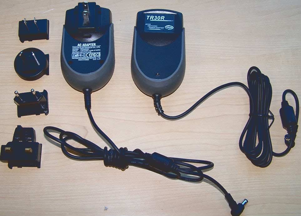
Click to zoom
Application Details
- Equipment Class
- DTS - Digital Transmission System
- Date of Grant
- Jul 17, 2005
- Application Purpose
- Original Equipment
- Date of Application
- Jul 17, 2005
- Equipment Note
- Ranger X Series
- Frequency Range
- 2412.00000000 - 2462.00000000
- Company
- Trimble Inc.
- Country
- United States
Documents & Files
Document Text
Text extracted from the exhibit documents filed with the FCC. Open a document above to read the original.
Users Manual
1 Contents Welcome 1 Device Hardware 2 Unit Set Up 3 Working with Your Unit 6 Settings on Your Unit 17 Connecting to Your PC 18 Communication 19 Caring for Your Unit 29 Environmental Considerations 31 Hardware Specifications 33 Environmental Specifications 33 Safe Use of Your Unit 34 Troubleshooting and FAQs 35 Regulatory Information 39 Declaration of Conformity 40 Welcome Congratulations on your purchase of one of the most advanced handheld computers available on the market today. The rugged design of your handheld allows you to work in harsh outdoor environments. You can operate your unit in blazing heat, subzero cold, driving rain or dusty job sites – places you could not take a consumer-grade handheld computer. NOTE: Not all the features discussed in this manual will apply to every unit, as many of the features are offered as options. If the feature described does not apply to your unit, please disregard that section. 2 Device Hardware Front Panel Back Panel Removable CF-Cap covers two CompactFlash slots and one SD slot CF-Cap Top View- without Cap Bottom View CompactFlash and SD card slots NOTE: Be sure to read the warranty and safety information in this manual prior to using your unit. PowerBoot coin screws PowerBoot Module Stylus holder Power Serial port USB host CF slot #1 type I External power USB client CF slot #2 type I & II SD Notification LED Hand strap 3 Unit Set Up 1. Attach the PowerBoot Module The PowerBoot Module TM that contains the batteries is shipped detached from the unit. Align the PowerBoot Module with the contacts facing down. Insert the top end of the PowerBoot Module first as shown, and then drop the PowerBoot Module into the unit. Secure by tightening the two screws with the stylus, a coin, or a screwdriver. 2. Attach the hand strap Insert the strap as shown onto the two small bolts located on the back of the unit, near the bottom of the PowerBoot Module. Now stretch the hand strap and insert the other end of the strap onto the two bolts at the top of the unit. 3. Charge your unit The AC charger that ships with your unit comes with adapters to fit almost every electrical outlet and voltage. Connect the correct adapter to the charger, plug the charger into an electrical outlet and plug the DC jack barrel end of the charger into the external power port on the PowerBoot Module. Charge the PowerBoot Module for approximately 4.5 hours. Warning! Be sure to always use the charger included with your unit. Use of other chargers will void your warranty. 4 4. Turning your unit on and off To turn your computer on, press the green Power key on the lower left hand corner of the keypad. To turn the computer off, press the Power key again. One of the most convenient features of the unit is “instant on” and “instant off” that happens every time the Power key is pressed. Also known as “suspend/resume”, it means that there is no waiting for the computer to boot up every time the unit is turned on. “Instant on” does not occur on the first boot-up. 5. Align the touchscreen When the unit first turns on (or after a hard reset) the touchscreen may require alignment. A series of targets is displayed in sequence on the screen. Use the stylus to tap the targets firmly and accurately to align the touchscreen. Sometimes it is necessary to repeat the alignment procedure more than once to provide a satisfactory calibration. 6. Using the CF and SD expansion slots Your unit contains two CompactFlash (CF) slots and one Secure Digital (SD) expansion slot. The SD slot is located within the walls of one of the CF slots. The SD slot is for memory cards only. SDIO devices such as cameras or GPS receivers will not operate in this slot. To access the CF and SD expansion slots, remove the CF-Cap TM . To do this, unscrew the screw on the top of the CF-Cap using the stylus, a coin or a screwdriver as shown, and slide the cap off the main unit. NOTE: When using smaller CF cards (such as memory or Bluetooth), it is critical that you attach a CF Card Pull Tab to the CF card before sliding the card into the slot. A Pull Tab will allow you to easily remove the CF card from the slot. Pull Tabs are part of the accessories included with your unit. Power 5 CF Slot #1 T ype I CF Slot #2 T ype I & II SD With the CF-Cap removed, the 2 CF and 1 SD expansion slots are visible. The CF slots are side by side, and the SD slot can be seen inside the CF slot #2 cavity. To insert a CF or SD card: - CF cards must be inserted with the front of the card facing toward the display side of the unit. CF slot #1 supports Type I cards. CF slot #2 supports Type I and II cards. - SD cards must be inserted with the front of the card facing away from the display. - Again, be sure to attach a Pull Tab to the smaller CF cards (such as memory or Bluetooth) before sliding the cards into the slots. - Gently insert the CF card or SD memory card into one of the two CF slots. Do not force the card into the slot. The pins can be damaged if the card is not aligned correctly. When replacing the CF-Cap, first be sure it is oriented correctly. The stylus holder in the CF-Cap is towards the front of the unit. Replace the CF-Cap and tighten the screw to reseal. The cap should be securely tightened, but do not over-tighten the screw. NOTE: Be sure to correctly orient the CF-Cap when you are reattaching it. The unit is NOT sealed when the cap is off or attached backwards. Water damage caused by improper installation of the CF-Cap is not covered by warranty. 6 Working with Your Unit Using the stylus The touchscreen on your unit works like a mouse on a PC. Use the stylus to navigate and select objects on the screen. Tap: Tap the screen with the stylus to select or open an item. Tapping is equivalent to clicking an item with the left mouse on your PC. Touch and hold: When you touch and hold, a circle of blue dots appears around the stylus to indicate that a pop-up menu will soon appear. Touching and holding is equivalent to right-clicking your PC mouse b…
Text truncated - open the document above for the full version.
Cover Letter(s)
L LL 7DSTM THEWAYTOGO TRIPODDATASYSTEMS ATRIMBLECOMPANY 345SWAveryAve. Corvallis,OR97333 541.753.9322 Fax541.757.7439 www.tdsway.com May19,2005 FederalCommunicationsCommission AuthorizationandEvaluationDivision 7435OaklandMillsRoad Columbia,Maryland21046 Towhomit mayconcern, We,theundersigned,herebyauthorizeNorthwestEMC,Inc.,toactonourbehalf,asouragent, inthefollowingmattersrelatedtotheFCCapprovalofourproducts:reportsubmittal,related correspondence,thesigningofalldocumentsrelatingtothesematters,andanyotherlawful activitynecessarytoobtainsuchcertification.AnyactcarriedoutbyNorthwestEMC,Inc.within thescopeof thisauthorizationshallhavethesameaffectasourown. Thisauthorizationshallexpire12monthsfromoriginaldate. Sincerely, ~oc(~ HardwareDevelopmentManager TripodDataSystems,Inc.
Cover Letter(s)
NORTHWEST EMC, INC. 22975 NW Evergreen Parkway, Suite 400 Hillsboro, OR 97124 July 10, 2005 Dear Application Examiner: On behalf of Tripod Data Systems, Inc., Northwest EMC, Inc. is submitting this application for the certification of Tripod’s USI radio module, FCC ID: S9E- RNGR80BT. It is an 802.11b / Bluetooth combo radio operating in the 2.4 GHz band. The radio module is installed in Tripod’s Ranger X Series handheld computer and is seeking limited modular approval for that mobile host configuration. Ranger X handheld computer will also contain a second radio module (Cirronet) that is currently seeking limited modular approval under FCC ID: S9E-RNGR2410. It is a 2.4 GHz frequency hopping spread spectrum radio. All radios in the Ranger X can transmit simultaneously – each radio through its own antenna. The USI radio utilizes two identical chip antennas that are integral to the printed circuit board. One antenna is used for the 802.11b portion, and the other antenna is used for the Bluetooth portion. This configuration satisfies the requirements of 47 CFR 15.203. The USI radio was previously certified under FCC ID: IXMWM-BB-AG-01. This new application for certification is required for the co-located exposure condition in Tripod’s Ranger X handheld. However, all the antenna direct connect test data from the previous certification continues to be representative, and is used in support of this application. New radiated spurious emissions data and AC powerline conducted emissions data was taken for Tripod’s Ranger X configuration and is documented in the Northwest EMC test report. The technical reports and exhibits demonstrate compliance with FCC rules 47 CFR 15.247 as a Digital Transmission System (DTS) transmitter. Your efforts in reviewing this application are greatly appreciated. Best regards, Northwest EMC, Inc.
Cover Letter(s)
NORTHWEST EMC, INC. 22975 NW Evergreen Parkway, Suite 400 Hillsboro, OR 97124 July 10, 2005 Dear Application Examiner: Tripod’s USI radio module, FCC ID: S9E-RNGR80BT is seeking limited modular approval. The radio meets the requirements for limited modular approval as detailed in FCC Public Notice DA00-1407. Compliance to each of the requirements is described below: 1. “The modular transmitter must have its own RF shielding.” The radio portion of the module is contained in its own RF shielding. The shielding is installed at the factory. Please see the Internal Photos exhibit. 2. “The modular transmitter must have buffered modulation/data inputs.” The EUT has buffered data inputs to insure compliance with Part 15 requirements under conditions of excessive data rates or over-modulation. Please see the Schematics exhibit. 3. “The modular transmitter must have its own power supply regulation.” The EUT has its own power supply regulation to insure compliance with Part 15 requirements regardless of the quality or level of external DC supplying the module from the host unit. Please see Schematics exhibit. 4. “The modular transmitter must comply with the antenna requirements of Section 15.203 and 15.204(c).” The EUT meets the FCC antenna requirements. Please see Antenna information exhibit and internal photos exhibit. 5. “The modular transmitter must be tested in a stand-alone configuration.” The EUT was not tested in a stand-alone configuration. The module was installed in Tripod’s Ranger X Series handheld computer. The Ranger X also contains a 2.4 GHz Frequency Hopping Spread Spectrum radio module, FCC ID: S9E- RNGR2410, that is currently seeking certification. This is why Tripod is seeking limited modular approval of their USI radio module in this host-specific configuration. 6. “The modular transmitter must be labeled with its own FCC ID number.” The EUT is not labeled with its own FCC ID number since it will always be factory installed by Tripod into their Ranger X Series handheld computer. The exterior of the Ranger X is labeled with the EUT’s FCC ID number. Please see FCC ID label & location exhibit. 7. “The modular transmitter must comply with any specific rule or operating requirements applicable to the transmitter and the manufacturer must provide adequate instructions along with the module to explain any such requirements.” The EUT is compliant with all applicable FCC rules. Detail instructions for maintaining compliance are given in the User Manual. 8. “The modular transmitter must comply with any applicable RF exposure requirements.” The EUT is compliant with all applicable RF exposure requirements. Please see the RF Exposure exhibit and the User Manual. Please contact me if you have additional questions. Your attention to this matter is greatly appreciated. Best regards, Greg Kiemel, Director of Engineering Northwest EMC, Inc.
Cover Letter(s)
L LL 7DSTM THEWAYTOGO TRIPODDATASYSTEMS ATRIMBLECOMPANY 345SWAveryAve. Corvallis,OR97333 541.752.9000 Fax541.750.7931 www.tdswoy.com June8, 2005 FederalCommunicationsCommission AuthorizationandEvaluationDivision 7435OaklandMillsRoad Columbia,Maryland21046 Towhomit mayconcern, Weherebyrespectfullyrequestthatundertheprovisionof 47CFR0.459,thedocumentslisted belowandattachedwiththisapplicationforcertificationbeprovidedwithconfidentialstatus. . Productschematics Frequencyblockdiagrams Theoriesofradiooperation . . Anyexhibit/ informationforwhichwehaverequestedconfidentiality,butwhichmaynotbe accordedsuchtreatmentbytheFCC,shouldbereturnedtous. Thedocumentslistedabovecontaintradesecretsthataretreatedasconfidentialbyus. Substantialcompetitiveharmtouscouldresultshouldtheybemadeavailabletothepublic. Sincerely, ~ DennisYork HardwareDevelopmentManager tfti
Cover Letter(s)
Northwest EMC TCB Compliance Opinion Revision 05//02 TRPD0007 - USI Information about the Applicant Applicant: Tripod Data Systems, Inc. Address: 345 SW Avery Ave City, State, Zip Corvallis, OR 97333 Test Requested By: Dennis York Model: 802.11b / Bluetooth combo radio installed in Tripod’s Ranger X Series FCC ID: S9E-RNGR80BT Agent Northwest EMC, Inc. Approval Type Certification Equipment Type Low power intentional radiator Rule Part 15.247 Overview This application for the certification of Tripod’s USI radio module, FCC ID: S9E-RNGR80BT. It is an 802.11b / Bluetooth combo radio operating in the 2.4 GHz band. The radio module is installed in Tripod’s Ranger X Series handheld computer and is seeking limited modular approval for that mobile host configuration. Ranger X handheld computer will also contain a second radio module (Cirronet) that is currently seeking limited modular approval under FCC ID: S9E-RNGR2410. It is a 2.4 GHz frequency hopping spread spectrum radio. All radios in the Ranger X can transmit simultaneously – each radio through its own antenna. The USI radio utilizes two identical chip antennas that are integral to the printed circuit board. One antenna is used for the 802.11b portion, and the other antenna is used for the Bluetooth portion. This configuration satisfies the requirements of 47 CFR 15.203. The USI radio was previously certified under FCC ID: IXMWM-BB-AG-01. This new application for certification is required for the co-located exposure condition in Tripod’s Ranger X handheld. However, all the antenna direct connect test data from the previous certification continues to be representative, and is used in support of this application. New radiated spurious emissions data and AC powerline conducted emissions data was taken for Tripod’s Ranger X configuration and is documented in the Northwest EMC test report. . Findings Finding: TCB 410 Is missing hyphen on FCC ID Resolution: Corrected document (with client approval) Recommendation All items have been resolved and completed to my satisfaction; therefore I recommend this application for approval. Signature Northwest EMC TCB Compliance Opinion Revision 05//02 TRPD0007 - USI Opinion Specification Requirements Description 15.207 Conducted Power Line Emissions Opinion: The Equipment meets the intent specified by the requirements listed above. Discussion: The Applicant has submitted test results in the form of a test report. Reference: Technical Report Specification Requirements Description 15.247( d ) Spurious Emissions, Radiated Emissions Opinion: The Equipment meets the intent specified by the requirements listed above. Discussion: The Applicant has submitted test results in the form of a test report. Reference: Technical Report Specification Requirements Description 2.1091/15.247 RF Exposure Opinion: The Equipment meets the intent specified by the requirements listed above. Discussion: The Applicant has submitted MPE estimates demonstrating compliance. Reference: RF Exposure Exhibit Specification Requirements Description Additional Requirements FCC Compliance requirements for Limited Modular Approval Opinion: The Equipment meets the intent specified by the requirements listed above. Discussion: The Applicant has submitted the required information in the test report. Reference: Letter supporting Limited Modular Approval
ID Label/Location Info
The information contained in this drawing is the sole property of Tripod Data Systems.Any reproduction in part or whole without the written permission of Tripod Data Systems is prohibited. REVISIONS DESCRIPTION PARTS LIST ITEM NO. PART NO. NOMENCLATURE OR DESCRIPTION MATERIAL SPECIFICATION QTY REQ'D Unless otherwise specified dimensions are in mm tolerances are: Tripod Data Systems A TrimbleCompany DO NOT MANUALL Y UPDATE ST BCase Lbl BT Wireless Artwork SCALE: FILE NAME: SHEET 1 of 1 SIZE: DWG. NO.: APPROVALS DATE MATERIAL: FINISH: DO NOT SCALE DRAWING DECIMALSANGLES .X + 0.1 + 1 DATE APPROVED REV. Preliminary Added “Contains Transmitter Module” Moved Bluetooth logo M750-0022-ART Notes: See ST Back Case Label mechanical drawing for specifications. Dimensions 1X: Text -- Arial Narrow Black CYMK 0 0 0 100 Graphics Contact: Jeanie Wenning 541-752-9000 � M750-0022-ART ST BCase Lbl BT Wireless Art.ai/pdf 1 2 3 6/2/05 6/7/05 6/8/05 Dennis York Dennis York Dennis York -50mm ruler 0 mm +50mm PRELIMINARY - NOT RELEASED YET Label w/BT Wireless Radio combo 2 3 RANGER X Series by Tripod Data Systems, Inc. TM Phone: 1-541-753-9322 www.tdsway.com ! See manual for battery, adaptor and regulatory information. Assembled in Mexico with foreign and domestic parts N324 0981 Tested to comply with FCC standards FOR HOME OR OFFICE USE 50.95±0.30 56.88±0.30 - + Input: DC 5.0 V Max 4.5 A X Contains Transmitter Module FCC ID: S9E-RNGR80BT IC: 5817A-RNGR80BT The information contained in this drawing is the sole property of Tripod Data Systems.Any reproduction in part or whole without the written permission of Tripod Data Systems is prohibited. REVISIONS DESCRIPTION PARTS LIST ITEM NO. PART NO. NOMENCLATURE OR DESCRIPTION MATERIAL SPECIFICATION QTY REQ'D Unless otherwise specified dimensions are in mm tolerances are: Tripod Data Systems A TrimbleCompany DO NOT MANUALL Y UPDATE ST Back Case Label Artwork SCALE: FILE NAME: SHEET 1 of 1 SIZE: DWG. NO.: APPROVALS DATE MATERIAL: FINISH: DO NOT SCALE DRAWING DECIMALSANGLES .X + 0.1 + 1 DATE APPROVED 3 3 REV. Preliminary Revised and Redrawn. Added add’l FCC Transmitter mod. Removed Radio info. Changed DC voltage to 5.0 V and symbol; Removed p/n from artwork. Changed “made in ...”. Changed p/n and file name to M750-0005-ART per mfg request M750-0005-ART Notes: See ST Back Case Label mechanical drawing for specifications. Dimensions 1X: Text -- Arial Narrow Black CYMK 0 0 0 100 Graphics Contact: Jeanie Wenning 541-752-9000 � M750-0005-ART ST Back Case Label Artwork.ai/pdf 1 2 3 5/4/05 5/18/05 5/26/05 Dennis York Dennis York Dennis York -50mm ruler 0 mm +50mm PRELIMINARY - NOT RELEASED YET 3 3 RANGER X Series by Tripod Data Systems, Inc. TM Phone: 1-541-753-9322 www.tdsway.com ! See manual for battery, adaptor and regulatory information. Assembled in Mexico with foreign and domestic parts N324 0981 Tested to comply with FCC standards FOR HOME OR OFFICE USE 50.95±0.30 56.88±0.30 - + Input: DC 5.0 V Max 4.5 A X Label w/no radios The information contained in this drawing is the sole property of Tripod Data Systems.Any reproduction in part or whole without the written permission of Tripod Data Systems is prohibited. REVISIONS DESCRIPTION PARTS LIST ITEM NO. PART NO. NOMENCLATURE OR DESCRIPTION MATERIAL SPECIFICATION QTY REQ'D Unless otherwise specified dimensions are in mm tolerances are: Tripod Data Systems A TrimbleCompany DO NOT MANUALL Y UPDATE ST BCase Lbl BT Wrelss Cir Artwork SCALE: FILE NAME: SHEET 1 of 1 SIZE: DWG. NO.: APPROVALS DATE MATERIAL: FINISH: DO NOT SCALE DRAWING DECIMALSANGLES .X + 0.1 + 1 DATE APPROVED REV. Preliminary Added “Contains Transmitter Module” Added second “Contains Transmitter Module” & moved Bluetooth logo M750-0023-ART Notes: See ST Back Case Label mechanical drawing for specifications. Dimensions 1X: Text -- Arial Narrow Black CYMK 0 0 0 100 Graphics Contact: Jeanie Wenning 541-752-9000 � M750-0023-ART ST BCase Lbl BT Wrelss Cir Art.ai/pdf 1 2 3 6/8/05 6/2/05 6/7/05 Dennis York Dennis York\ Dennis York 2 3 -50mm ruler 0 mm +50mm PRELIMINARY - NOT RELEASED YET RANGER X Series by Tripod Data Systems, Inc. TM Phone: 1-541-753-9322 www.tdsway.com ! See manual for battery, adaptor and regulatory information. Assembled in Mexico with foreign and domestic parts N324 0981 Tested to comply with FCC standards FOR HOME OR OFFICE USE 50.95±0.30 56.88±0.30 - + Input: DC 5.0 V Max 4.5 A X Contains Transmitter Module FCC ID: S9E-RNGR80BT IC: 5817A-RNGR80BT Label w/BT Wireless & Cirronet Contains Transmitter Module FCC ID: S9E-RNGR2410 IC: 5817A-RNGR2410
Operational Description
ANT-2.45-CHP-x 2.45GHz ULTRA COMPACT CHIP ANTENNA DATA GUIDE Revised 02/17/05 AAnnyy 22..44GGHHzz wwiirreelleessss pprroodduucctt iinncclluuddiinngg:: ■Bluetooth ■802.11 ■ZigBee ■Wireless PCMCIA Cards ■Telemetry ■Data Collection ■Industrial Process Monitoring ■Compact Wireless Products ■External Antenna Elimination APPLICATIONS ■Incredibly compact SMD package ■Superior LTCC technology ■50Ωcharacteristic impedance ■Low loss ■Wide bandwidth ■Favorable linear polarization ■> Unity gain ■No external matching required ■Highly stable over temperature and humidity ■Fully hand- and reflow-assembly compatible ■Cost-effective FEATURES The exciting ANT-2.45-CHP is one of the world’s smallest high-performance 2.4GHz Chip Antennas. It is ideal for all 2.4GHz applications including Bluetooth, 802.11, Home RF, ZigBee and other popular standards. The antenna uses advanced Low Temperature Co-fired Ceramic (LTCC) technology and a proprietary element to achieve superior size and performance characteristics. The tiny SMD package measures a mere 6.5mm (L) x 2.2mm (W) x 1.0mm (H) and is compatible with hand- and reflow-assembly. Favorable electrical specifications, stability, and outstanding cost-effectiveness make it the logical choice for a wide variety of applications. DESCRIPTION PHYSICAL DIMENSIONS 2.45GHz ULTRA COMPACT CHIP ANTENNA DATA GUIDE Actual Size PART #DESCRIPTION ANT-2.45-CHP-x2.45GHz Ultra-Compact Chip Antenna x= “T” for Tape/Reel, “B” for Bulk Standard Reel is 3,000 pcs. Quantities less than 3,000 pcs. supplied in bulk. ORDERING INFORMATION 1.00mm 2.20mm 6.50mm SPECIFICATIONS Page 2 Dimensions (mm)6.5(L) x 2.2(W) x 1.0(H) Operating/Storage Temperature-40~+85°C ConstructionLTCC PHYSICAL SPECIFICATIONS Center Frequency2.45GHz Bandwidth180.0MHz PatternOmni-directional PolarizationLinear VSWR<2.0 (Max.) Maximum Gain+0.5dBi Impedance50Ω Power Handling3W (Max.) ELECTRICAL PERFORMANCE PAD LAYOUT PIN CONFIGURATIONLAYOUT DETAILS 2.4 Pin No. 1 1 Feed Termination Solder Termination Pin connects to the transmitter or receiver. Pin is soldered for physical support. There is no electrical connection. 2 2 Pin Description 2.4 No ground plane or traces under the antenna Ground plane on bottom layer for counterpoise 50 ohm microstrip line No electrical connection. For physical support only PCB pads for the CHP 2.54mm 1.02mm 6.60mm Page 3 REFLOW SOLDERING PROFILE ASSEMBLY CONSIDERATIONS The antenna is designed to support hand or automated assembly. To avoid damage to the part, the reflow/solder guidelines found below should be carefully followed. The antenna is single ended meaning that one pad is electrically connected while the other is for mechanical support only. The antenna terminals are not interchangeable so polarity must be observed during assembly. Hand Soldering This antenna is designed for high-volume automated assembly, however, it may be successfully attached by hand assembly techniques. A hand-solder temperature of 225° or lower should be used. Do not exceed a 10 sec. heating time. Reflow Temperature Profile The single most critical stage in the automated assembly process is the reflow process. The reflow profile below should be closely followed since excessive temperatures or transport times during reflow will irreparably damage the antennas. Assembly personnel will need to pay careful attention to the oven's profile to ensure that it meets the requirements necessary to successfully reflow all components while still meeting the limits mandated by the antennas themselves. Absolute Maximum Solder Times Hand-Solder Temp. TX +225°C for 10 Sec. Hand-Solder Temp. RX +225°C for 10 Sec. Recommended Solder Melting Point +180°C Reflow Oven: +220°C Max. (See adjoining diagram) Page 4 LAYOUT CONSIDERATIONS The antenna’s wide bandwidth and good stability allow it to perform well and accommodate differing layout requirements. Despite this, proper layout is vital to ensure correct operation. Improper placement of planes, traces or system components will result in nulls or complete detuning. Failure by the designer to respect and account for these requirements will result in unsatisfactory performance. Ideally the antenna will be mounted on the board in such a way as to allow an unobstructed field of view. The area under the backside of the antenna must be free of components, traces, and planes. Components may be placed to the rear of the antenna in the ground plane counterpoise area. The feed trace from the RF stage to the antenna must be a microstrip trace or coax transmission line and should be kept as short as practical. Two sample layouts and their associated data are illustrated on the following pages. They are intended to be representative and it is not necessary to follow them precisely. They do however, exhibit layout techniques and the differences that occur with differing size PCB’s and layouts. After your own layout is complete the performance of the antenna in your specific product should be carefully checked using tools like a network analyzer. In some cases the size of the product’s PCB, proximity of the case or other factors may make a custom version of the antenna necessary. You may contact Antenna Factor for more information. Effective DielectricWidth/HeightDielectricCharacteristic Constant(W/d)ConstantImpedance 4.81.83.5950.0 423.0751.0 2.5532.1248.0 Microstrip Formulas (Er = Dielectric constant of PC board material) MICROSTRIP CALCULATIONS Page 5 TEST BOARD PATTERNS RETURN LOSS Test Board 1 Test Board 2 35 40 5 10 50Ω Transmission Line (Top Layer) Ground plane (Bottom Layer) Test board-2 30 30 14 20 14 50Ω Transmission Line Ground plane (Top and Bottom Layers) Test Board 1 Unit: mm Board Thickness: 0.023” Board Material: FR4 Test Board 2 Unit: mm Board Thickness: 0.031” Board Material: FR4 50ΩMicrostrip trace (Top layer) 50ΩMicrostrip trace Ground plane (Bottom layer) Ground plane (Top and bottom layers) Page 6 PATTERN TEST PCB 1 2.45GHz H-Plane Vertical Horizontal 2.45GHz H-Plane Vertical 2.…
Text truncated - open the document above for the full version.
RF Exposure Info
Compliance with 47 CFR 15.247(i) “Systems operating under the provisions of this section shall be operated in a manner that ensures that the public is not exposed to radio frequency energy levels in excess of the Commission's guidelines. See § 1.1307(b)(1) of this chapter.” The EUT will only be used with a separation distance of 20 centimeters or greater between the antenna and the body of the user or nearby persons and can therefore be considered a mobile transmitter per 47 CFR 2.1091 (b). Up to two radio modules can be installed in the EUT – each operating in the 2.4 GHz band: A FHSS radio module, and an 802.11b/Bluetooth combo module. The radios can transmit simultaneously. Each radio transmits through its own antenna. The total transmit power is less than 1.5 W (ERP), therefore the EUT is categorically excluded from routine environmental evaluation per 47 CFR 2.1091(c). The MPE estimates are as follows: Table 1 in 47 CFR 1.1310 defines the maximum permissible exposure (MPE) for the general population. The exposure level at a 20 cm distance from the EUT’s transmitting antenna is calculated using the general equation: S = (PG)/4πR 2 Where: S = power density (mW/cm 2 ) P = power input to the antenna (mW) G = numeric power gain relative to an isotropic radiator R = distance to the center of the radiation of the antenna (20 cm = limit for MPE estimates) PG = EIRP Solving for S, the maximum power densities 20 cm from the transmitting antennas are summarized in the tables on the following pages: MPE Estimates for Self Co-located Device Antenna Type Antenna Part No. Transmit Frequency Max Peak Conducted Output Power Antenna Gain Minimum Antenna Cable Loss Power Density @ 20 cm General Population Exposure Limit from 1.1310 Ratio of Power Density to the Exposure Limit (MHz)(mW)(dBi)(dB) (mW/cm 2 )(mW/cm 2 ) OmniPW5S-2400-02-04240047.86200.01510.01509 Worst Case Ratio of Power Density to the Exposure Limit = 0.01509 Antenna T ype Antenna Part No.Transmit Max Peak Antenna GainMinimum Power General Ratio of Power (MHz)(mW)(dBi)(dB) (mW/cm 2 )(mW/cm 2 ) ChipANT-2.45-CHP-X240028.180.500.00610.00629 Worst Case Ratio of Power Density to the Exposure Limit = 0.00629 Antenna T ype Antenna Part No.Transmit Max Peak Antenna GainMinimum Power General Ratio of Power (MHz)(mW)(dBi)(dB) (mW/cm 2 )(mW/cm 2 ) ChipANT-2.45-CHP-X24001.760.500.0003910.00039 Worst Case Ratio of Power Density to the Exposure Limit = 0.00039 Per Note 24 shown below, the Sum of Worst Case Power Ratios cannot exceed 1.0 FHSS Radio Worst Case Ratio of Power Density to the Exposure Limit 802.11b Radio Worst Case Ratio of Power Density to the Exposure Limit Bluetooth Radio Worst Case Ratio of Power Density to the Exposure Limit Sum of Worst Case Ratios (Power Density to the Exposure Limit) FCC Limit for Sum of Worst Case Ratios 0.015090.006290.000390.021771.0PASS FHSS Radio Bluetooth Radio FCC ID: S9E-RNGR2410 FCC ID: S9E-RNGR80BT The results shown in the above table are equivalent to the Sum of the EIRP of the Two Co-located Transmitters (EIRP TX1 + EIRP TX2) compared to the exposure limit. The benefit of this method, is that accounts for transmitters operating at different frequencies against different exposure limits. Worst Case Co-located Exposure Condition 802.11 (b) Radio Excerpts from TCB Training, April 3, 2002, “Mobile Transmitters”, Slide 6: “Devices operating in multiple frequency bands When RF exposure evaluation is required for TCB approval o Separate antennas – estimated minimum separation distances may be considered for the frequency bands that do not require evaluation or TCB approval, however, the estimated distance should take into account the effect of co-located transmitte…
Text truncated - open the document above for the full version.
Contact Information
Applicant
Katherine Allen(Compliance Engineer)
Test Firm
Northwest EMC, Inc.Greg Kiemel
Technical Specifications
| # | Rule Parts | Frequency Range | Power Output |
|---|---|---|---|
| 2 | 15C | 2.41 GHz - 2.46 GHz | 28.00 mW |
Other Applications from Trimble Inc.
S9E-GS200A
Sep 26, 2024Wireless Load Cell Sensor
Equipment Class
DTS - Digital Transmission SystemS9E-GS200G
Sep 26, 2024Wireless Line Riding Tensiometer & Rope payout sensor
Equipment Class
DTS - Digital Transmission SystemS9E-GS200C
Sep 26, 2024Wireless Boom Angle Sensor and Powered Boom Angle Sensor
Equipment Class
DTS - Digital Transmission SystemS9E-GS200B
Sep 26, 2024Wireless Wind Speed Sensor
Equipment Class
DTS - Digital Transmission SystemS9E-GS200D
Sep 26, 2024Wireless Slew Angle Sensor
Equipment Class
DTS - Digital Transmission System