S9L64-04-05-06-08RFID Label Printer
Avery Dennison Deutschland GmbH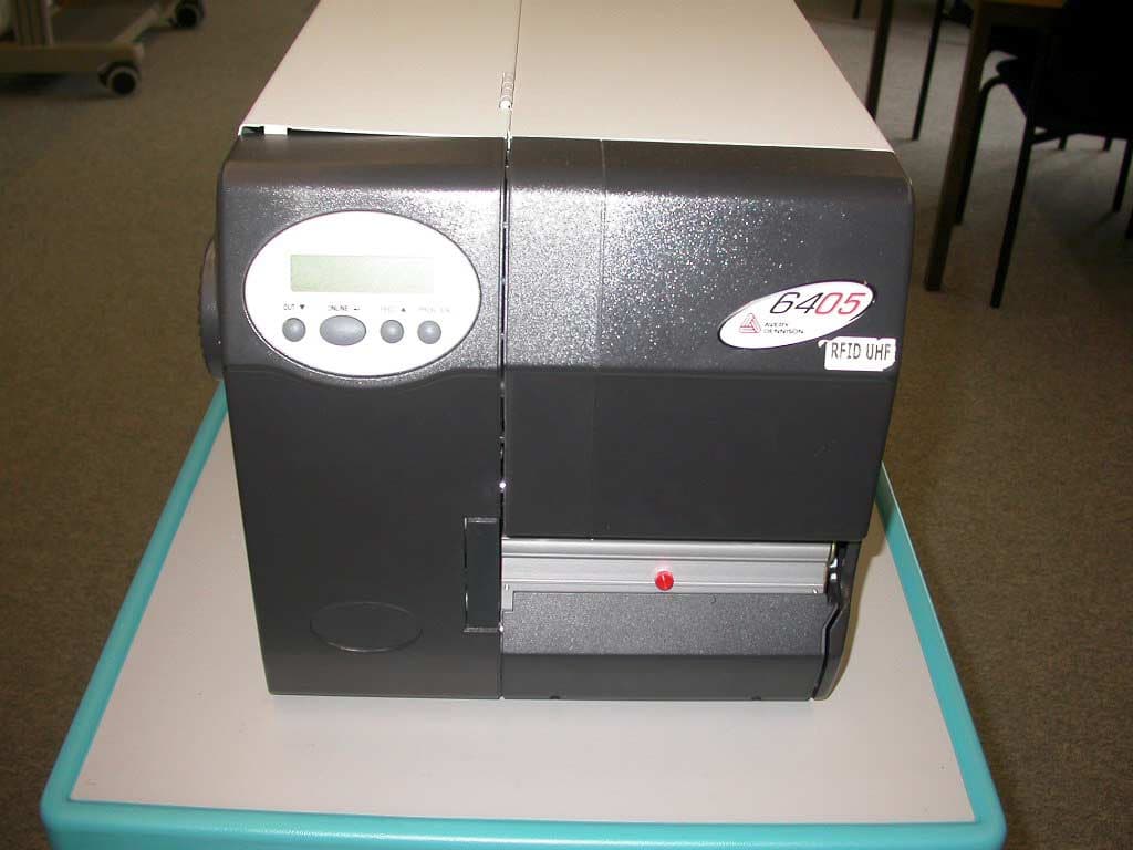
Click to zoom
Application Details
- Equipment Class
- DSS - Part 15 Spread Spectrum Transmitter
- Date of Grant
- Jul 07, 2005
- Application Purpose
- Original Equipment
- Date of Application
- Jul 07, 2005
- Equipment Note
- RFID Label Printer
- Frequency Range
- 902.40000000 - 926.50000000
- Country
- Netherlands
Documents & Files
Document Text
Text extracted from the exhibit documents filed with the FCC. Open a document above to read the original.
Users Manual
03/05 Rev. 3.01-02 USER + SERVICE MANUAL 64-xx – 64-xx dispenser – TT4 Specifications Device Types, Use......................................... 2 64-0x Basic ................................................ 2 64-0x Peripheral ......................................... 2 64-0x Dispenser M ..................................... 2 64-0x Dispenser A...................................... 3 TT4 ............................................................. 3 Options ....................................................... 3 Technical Specifications ................................ 5 Dimensions ................................................ 5 Performance data....................................... 6 Label material............................................. 8 Ribbon ........................................................ 9 Connections, device data ........................... 9 Ambient conditions ..................................... 9 Interfaces ................................................... 9 Electronics................................................ 10 Operation features ................................... 10 Status messages / Test functions ............ 10 Test certificates ........................................ 10 Appendix ...................................................... 11 Automatic ribbon economy....................... 11 Important distances to the print line ......... 12 TT4 Specifications.................................... 13 Index ............................................................ 14 03/05 Rev. 3.01-02 USER + SERVICE MANUAL Specifications 64-xx – 64-xx dispenser – TT4 2 Device Types, Use 64-0x Basic The x in the printer name stands for 4, 5, 6 or 8. The higher this number is, the wider label material can be used with this printer. • Monotone printing of labelling materials for thermal and thermotransfer processes • Printing on different materials, e.g. cardboard or self-adhesive labels • Processing roll and fan-folded material • Print width: -- 64-04 up to 106.6 mm -- 64-05 up to 127.9 mm -- 64-06 up to 159.9 mm -- 64-08 up to 213.2 mm • Resolution: 300 dpi • Interfaces: RS 232, RS 422/485 (optional), USB, Centronics, Ethernet (optional) ̄ The 64-0x Basic may not be used with peripheral devices! 64-0x Peripheral • Basic equipment as 64-0x Basic • The 64-0x Peripheral is additionally equipped with a motor driver and a connector for peripheral devices. Thus it offers the possibility of driving a cutter or a rewinder. 64-0x Dispenser M • Basic equipment as 64-0x Peripheral • Additional features: Dispensing edge and internal backing paper rewinder • Dispensing of self-adhesive labels after printing; the backing paper is wound up inside of the printer. • „M“ stands for manual application of the labels, what means that the label is taken off the dispensing edge and is applied to the product by hand. For this reason, the dispensing edge provides a light barrier which triggers the dispensing of the next label, if the current one is taken off. ̄ Alternatively, the dispensing can be triggered by a foot switch. The switch must be connected to the optional single-start connector. 03/05 Rev. 3.01-02 USER + SERVICE MANUAL Specifications 64-xx – 64-xx dispenser – TT4 3 64-0x Dispenser A • Basic equipment as 64-0x Peripheral • Additional features: Dispensing edge and internal backing paper rewinder • Dispensing of self-adhesive labels after printing; the backing paper is wound up inside of the printer. • “A” stands for automatic label application, what means, that the label is applied by an applicator. The dispensing edge is longer than the type “M” edge and has no light barrier. TT4 • Label printer based on 64-04 • Monotone printing of labelling materials for thermal and thermotransfer processes • Print width up to 98.0 mm • Automatic label material feed from 4 material sources: One roll material unwinder and three compartments for leporello material. The compartments are placed in a magazin below the printer. Options Internal Options ...should be factory-fitted or installed by a service engineer: • Reflex sensor: Light barrier fork that apart from the transmission sensor, also contains a reflex sensor. • Fullsize sensor: Punch sensor which can be shifted across the full material width. ̄ The fullsize sensor can not be used under one of the following conditions: -- The printer is a 64-0x Dispenser (type A or M). -- The printer is operated with the online verifier (see below) option. • USI (Universal Signal Interface): can e.g. be used to control an applicator or a scanner. • Options board with an additional serial interface (COM 2) and a PS/2 keyboard connector. • Antistatic kit: reduces electrostatic charge, which can especially arise of the processing of plastic labels. Electrostatic discharge can damage or destroy electronic circuits of the printer. • Realtime clock • RS 422/485 interface, instead of RS 232 • Single-Start option: Connector for a foot switch or another external signal, which is supposed to start or stop the printer. 03/05 Rev. 3.01-02 USER + SERVICE MANUAL Specifications 64-xx – 64-xx dispenser – TT4 4 External Options ...do not require any special alterations to the printer, however, the printer must be prepared for the use of peripheral devices: • Cutter: Optional high-performance, low-noise cutter with double-cut function from 1 to 5 mm • Rewinder: is mounted to the printer and rewinds the printed label materials with the printed side facing inwards or outwards • Online Verifier: The online verifier (OLV) checks printed bar code immediately after printing it. If the bar code has not been printed or has not been printed in a readable way, the OLV stopps the printer. • Keyboard for standalone operation • Foot switch for triggering the label dispenser (printer must be equipped with single-start option) 03/05 Rev. 3.01-02 USER + SERVICE MANUAL Specifications 64-xx – 64-xx dispenser – TT4 5 Technical Specifications Dimensions Fig. 1 Dimensions of the 64-xx s…
Text truncated - open the document above for the full version.
Users Manual
Valid for the following printers: USER MANUAL Rev. 3.02, Release 03/2005 © 2003, Avery Dennison Deutschland GmbH, Ohmstraße 3, 85386 Eching, Germany. All rights reserved. 64-0464-04 Dispenser 64-0564-05 Dispenser 64-0664-06 Dispenser 64-0864-08 Dispenser CopyrightSymbols Using the Documentation Safety Notes Commissioning and Operation Setup Advanced Applications Maintenance Info-Printouts and Parameters Status Reports Internal Fonts Specifications Accessories USER MANUAL Fig.: 64-05 (Delivered version may deviate from the picture)
Users Manual
11/04 Rev. 3.01-01OPERATOR / SERVICE MANUAL All Printers Safe Operation of Thermotransfer Label Printers Information and qualifications ....................... 2 Where are warnings given? ...................... 2 Warnings in the text .................................. 2 General safety notes ................................. 3 Information must be made available ......... 3 Ensure necessary qualifications ................ 4 Machine operating safety .............................. 5 Appropriate use ......................................... 5 Protect against injuries that can result from electrical current ........................................ 5 Protect against injuries that can result from mechanical actions .................................... 5 Disposal measures ........................................ 6 11/04 Rev. 3.01-01OPERATOR / SERVICE MANUALSafety All Printers 2 Information and qualifications Where are warnings given? General notes on safety are found in this section. Special safety notes and warnings are provided at the at the top of descripti- ons of possibly dangerous operations in the user and service manual of the printer. ̄Warning notes and warning symbols are also attached directly to the de- vices and device components. Pay attention to these safety notes as well! Warnings in the text Important text passages which must absolutely be followed are particularly marked for special attention: WARNING! A warning notice indicates risks which could result in death or serious injury of the personnel! «The notice contains safety instructions on how to safeguard possibly affec- ted personnel. The instructions must be followed. CAUTION! A caution notice indicates risks which, if unheeded, could lead to material damage or bodily injury (minor injuries). «The notice contains instructions on how to prevent damage or injury. The instructions must be followed. 11/04 Rev. 3.01-01OPERATOR / SERVICE MANUALSafety All Printers 3 General safety notes Information must be made available This operating manual «is to be stored at the machine operating location and made accessible to the operator. «is to be maintained in legible condition. «Safety and warning notices attached to the machine must be kept clean and legible. Missing or damaged warning labels and plates are to be replaced. WARNING! Safe and efficient operation of the printer can only be guaranteed if you observe all necessary information. «Before operating the printer, read the operating instructions and all other notes carefully. «Observe the additional safety and warning notes on the machine. «Only operate the printer using the system voltage indicated on the name- plate! «Only connect the printer to a grounded power socket fitted to authorized standards! «Make sure that the power supply socket for the printer is readily accessible! «Only use the printer in enclosed areas with normal environmental conditi- ons (standard office temperatures)! «Only operate the printer when the cover is closed! «Only trained and authorized personnel should operate the printer! «During operation, the printhead can become hot! Care should be taken when touching the printhead! «Do not make any modifications or any additional casing for the printer! «Do not allow any liquids to enter into the printer! «Repairs to the printer may only be performed by authorized specialists who are aware of the risks involved! «In case of emergency, switch off the printer and disconnect the power supply cable! «Before cleaning, switch off the printer and disconnect from the power! «Only use original accessories! «Connect the printer only to devices that fulfil SELV (safety extra-low voltage) circuit requirements to EN 60950! «Keep long hair, loose jewellery, long sleeves, etc. away from rotating parts of the printer! 11/04 Rev. 3.01-01OPERATOR / SERVICE MANUALSafety All Printers 4 Ensure necessary qualifications «Only allow the machine to be operated, adjusted and serviced by instructed and authorised personnel. «Train at least 2 persons to operate the machine. Instruction of the operating personnel must ensure – that operating personnel can use the machine independently and without posing a danger. – that operating personnel can remedy minor operational malfunctions them- selves. «Make label materials for test purposes available in sufficient quantities. «Moreover, personnel are to be regularly instructed about work safety and en- vironmental protection issues. «The responsibilities for operation, adjustment and servicing of the machine must be clearly defined and consistently maintained. «Only make adjustments to the machine in accordance with this manual and with all due care. ServiceSpecial servicing, fault searching and fault correction are to be carried out by the manufacturer, his appointees or other authorised service agents. This also includes the optional installation and refitting of components. 11/04 Rev. 3.01-01OPERATOR / SERVICE MANUALSafety All Printers 5 Machine operating safety Appropriate use Thermotransfer label printers are designed for printing label material, using the thermal or thermal transfer printing process. It is possible to use a wide range of label materials and thermal transfer ribbons, which must both be supplied in shape of rolls. The actual stipulated usage is detailed in the technical specifications of the respective devices. PFor details refer to topic section „Specifications“ in the user manual of the printer. Avery Dennison assumes no liability for damage due to improper use of the printer. Protect against injuries that can result from electrical current Protect against injuries that can result from mechanical actions WARNING! The printer is connected with the mains supply! Contact with energised components can result in life-endangering currents through the body as well as burns. «Only put the machine into operation when installed in a correctly installed housing. «The housing may only be removed by trained personnel when the machine is …
Text truncated - open the document above for the full version.
Cover Letter(s)
Request for Confidentiality in accordance with 47 CFR 0.459 Date: 24 May 2005 PHOENIX TEST-LAB GmbH Königswinkel 10 D32825 Blomberg Germany RE: Certification Application FCC ID: S9L64-04-05-06-08 Please be advised that the following information is to be held confidential on behalf of Avery Dennison Deutschland GmbH: • Schematics • Parts Lists • Block Diagram • Technical Description The application contains technical information which Avery Dennison Deutschland GmbH deems to be trade secrets and proprietary. If made public, the information might be used to the disadvantage of the applicant in the market place. Thank you for your attention to this matter.
External Photos
Pro Seite darf nur 1 Foto sein
Internal Photos
FCC ID S9L64-04-05-06-08 Antenna holder FCC ID S9L64-04-05-06-08 Module FCC ID S9L64-04-05-06-08 FCC ID S9L64-04-05-06-08 FCC ID S9L64-04-05-06-08
Parts List/Tune Up Info
Sheet1 Page 1 Part TypeDesignatorFootprintPart Field 1Part Field 2Part Field 3Part Field 4 0R1.1510402SRES.CHIPP0.0KJCT-ND5% 1/16WPANASONIC 0R1.1500402SRES.CHIPP0.0KJCT-ND5% 1/16WPANASONIC 0.5pFC1.460402SCap, ChipPCC0R5CQCT-ND+-0.25pF,NPO,50VPanasonic 0.5pFC1.490402SCap, ChipPCC0R5CQCT-ND+-0.25pF,NPO,50VPanasonic 0.5pFC1.450402SCap, ChipPCC0R5CQCT-ND+-0.25pF,NPO,50VPanasonic 1.00KR1.1170402SRES.CHIPP1.00KLCT-ND1% 1/16WPANASONIC 1.00KR1.1250402SRES.CHIPP1.00KLCT-ND1% 1/16WPANASONIC 1.00KR1.100402SRES.CHIPP1.00KLCT-ND1% 1/16WPANASONIC 1.00KR1.1160402SRES.CHIPP1.00KLCT-ND1% 1/16WPANASONIC 1.00KR1.1150402SRES.CHIPP1.00KLCT-ND1% 1/16WPANASONIC 1.00KR1.670402SRES.CHIPP1.00KLCT-ND1% 1/16WPANASONIC 1.00KR1.390402SRES.CHIPP1.00KLCT-ND1% 1/16WPANASONIC 1.00KR1.1080402SRES.CHIPP1.00KLCT-ND1% 1/16WPANASONIC 1.00KR1.310402SRES.CHIPP1.00KLCT-ND1% 1/16WPANASONIC 1.00KR1.750402SRES.CHIPP1.00KLCT-ND1% 1/16WPANASONIC 1.00KR1.1070402SRES.CHIPP1.00KLCT-ND1% 1/16WPANASONIC 1.0pFC1.580402SCap, ChipPCC010CQCT-ND+-0.25pF,NPO,50vPanasonic 1.0pFC1.510402SCap, ChipPCC010CQCT-ND+-0.25pF,NPO,50VPanasonic 1.0pFC1.1280402SCap, ChipPCC010CQCT-ND+-0.25pF,NPO,50vPanasonic 1.0pFC1.1290402SCap, ChipPCC010CQCT-ND+-0.25pF,NPO,50vPanasonic 1.0pFC1.280402SCap, ChipPCC2252CT-ND+-0.1pF,COG,25VPanasonic 1.0pFC1.1310402SCap, ChipPCC010CQCT-ND+-0.25pF,NPO,50vPanasonic 1.0pFC1.1300402SCap, ChipPCC010CQCT-ND+-0.25pF,NPO,50vPanasonic 1.0uFC1.320603RCap, ChipPCC1787CT-ND/DIGIKEY+80%-20%,10VPanasonic 1.0uFC1.40603RCap, ChipPCC1787CT-ND+80-20%,Y5V,10VPanasonic 1.0uFC1.1230603RCap, ChipPCC1787CT-ND/DIGIKEY+80%-20%,10VPanasonic 1.0uFC1.950603RCap, ChipPCC1787CT-ND/DIGIKEY+80%-20%,10VPanasonic 1.0uFC1.1170603RCap, ChipPCC1787CT-ND/DIGIKEY+80%-20%,10VPanasonic 1.0uFC1.110603RCap, ChipPCC1787CT-ND+80-20%,Y5V,10VPanasonic 1.0uFC1.180603RCap, ChipPCC1787CT-ND+80-20%,Y5V,10VPanasonic 1.0uFC1.150603RCap, ChipPCC1787CT-ND+80-20%,Y5V,10VPanasonic 1.0uFC1.70603RCap, ChipPCC1787CT-ND+80-20%,Y5V,10VPanasonic 1.0uFC1.120603RCap, ChipPCC1787CT-ND+80-20%,Y5V,10VPanasonic 1.0uFC1.920603RCap, ChipPCC1787CT-ND/DIGIKEY+80%-20%,10VPanasonic 1.0uFC1.1200603RCap, ChipPCC1787CT-ND/DIGIKEY+80%-20%,10VPanasonic Sheet1 Page 2 1.0uFC1.1140603RCap, ChipPCC1787CT-ND/DIGIKEY+80%-20%,10VPanasonic 1.0uFC1.20603RCap, ChipPCC1787CT-ND+80-20%,Y5V,10VPanasonic 1.0uFC1.380603RCap, ChipPCC1787CT-ND+80-20%,Y5V,10VPanasonic 1.1pFC1.500402SCap, ChipPCC010CQCT-ND+-0.25pF,NPO,50VPanasonic 1.1pFC1.350402SCap, ChipPCC2252CT-ND+-0.1pF,COG,25VPanasonic 1.1pFC1.360402SCap, ChipPCC2252CT-ND+-0.1pF,COG,25VPanasonic 1.1pFC1.290402SCap, ChipPCC2252CT-ND+-0.1pF,COG,25VPanasonic 1.8pFC1.520402SCap, ChipPCC1R5CQCT-ND+-0.25pF,NPO,50VPanasonic 2.2nHnL1.60402SInduc. Chip0805-2N2XGBW+-5%.100mACoilCraft 2.2nHnL1.280402SInduc. Chip0805-2N2XGBW+-5%.100mACoilCraft 2.2nHnL1.290402SInduc. Chip0805-2N2XGBW+-5%.100mACoilCraft 2.2nHnL1.50402SInduc. Chip0805-2N2XGBW+-5%.100mACoilCraft 2N7002U1.14SOT-23FETDual N-channel2N700250V, 3 OhmN-FET 2N7002U1.28SOT-23FETDual N-channel2N700250V, 3 OhmN-FET 2N7002U1.32SOT-23FETDual N-channel2N700250V, 3 OhmN-FET 2N7002U1.35SOT-23FETDual N-channel2N700250V, 3 OhmN-FET 2N7002U1.9SOT-23FETDual N-channel2N700250V, 3 OhmN-FET 2N7002U1.10SOT-23FETDual N-channel2N700250V, 3 OhmN-FET 2N7002U1.36SOT-23FETDual N-channel2N700250V, 3 OhmN-FET 2N7002U1.24SOT-23FETDual N-channel2N700250V, 3 OhmN-FET 2N7002U1.12SOT-23FETDual N-channel2N700250V, 3 OhmN-FET 2N7002U1.7SOT-23FETDual N-channel2N700250V, 3 OhmN-FET 2N7002U1.8SOT-23FETDual N-channel2N700250V, 3 OhmN-FET 2N7002U1.17SOT-23FETDual N-channel2N700250V, 3 OhmN-FET 2N7002U1.18SOT-23FETDual N-channel2N700250V, 3 OhmN-FET 2N7002U1.27SOT-23FETDual N-channel2N700250V, 3 OhmN-FET 2N7002U1.11SOT-23FETDual N-channel2N700250V, 3 OhmN-FET 2N7002U1.13SOT-23FETDual N-channel2N700250V, 3 OhmN-FET 2N7002U1.31SOT-23FETDual N-channel2N700250V, 3 OhmN-FET 2N7002U1.5SOT-23FETDual N-channel2N700250V, 3 OhmN-FET 2N7002U1.26SOT-23FETDual N-channel2N700250V, 3 OhmN-FET 2N7002U1.19SOT-23FETDual N-channel2N700250V, 3 OhmN-FET 2N7002U1.20SOT-23FETDual N-channel2N700250V, 3 OhmN-FET 2N7002U1.25SOT-23FETDual N-channel2N700250V, 3 OhmN-FET 3.0pFC1.1270402SCap, ChipPCC030CQCT-ND+-0.25pF,NPO,50VPanasonic 3.0pFC1.1260402SCap, ChipPCC030CQCT-ND+-0.25pF,NPO,50VPanasonic Sheet1 Page 3 3.01KR1.360402SRES.CHIPP1.00KLCT-ND1% 1/16WPANASONIC 3.01KR1.1440402SRES.CHIPP3.01KLCT-ND1% 1/16WPANASONIC 3.01KR1.280402SRES.CHIPP1.00KLCT-ND1% 1/16WPANASONIC 3.01KR1.350402SRES.CHIPP3.01KLCT-ND1% 1/16WPANASONIC 3.01KR1.1450402SRES.CHIPP3.01KLCT-ND1% 1/16WPANASONIC 3.01KR1.270402SRES.CHIPP3.01KLCT-ND1% 1/16WPANASONIC 3.3KR1.970402SRES.CHIPPDC1838CT-ND1% 1/16WYAGEO 3.3KR1.680402SRES.CHIPPDC1838CT-ND1% 1/16WYAGEO 3.3KR1.980402SRES.CHIPPDC1838CT-ND1% 1/16WYAGEO 3.3KR1.830402SRES.CHIPPDC1838CT-ND1% 1/16WYAGEO 3.3KR1.1180402SRES.CHIPPDC1838CT-ND1% 1/16WYAGEO 3.3KR1.950402SRES.CHIPPDC1838CT-ND1% 1/16WYAGEO 3.3KR1.1190402SRES.CHIPPDC1838CT-ND1% 1/16WYAGEO 3.3KR1.1210402SRES.CHIPPDC1838CT-ND1% 1/16WYAGEO 3.3KR1.1200402SRES.CHIPPDC1838CT-ND1% 1/16WYAGEO 3.3KR1.900402SRES.CHIPPDC1838CT-ND1% 1/16WYAGEO 3.3KR1.820402SRES.CHIPPDC1838CT-ND1% 1/16WYAGEO 3.3KR1.850402SRES.CHIPPDC1838CT-ND1% 1/16WYAGEO 3.3KR1.870402SRES.CHIPPDC1838CT-ND1% 1/16WYAGEO 3.3KR1.760402SRES.CHIPPDC1838CT-ND1% 1/16WYAGEO 3.3KR1.810402SRES.CHIPPDC1838CT-ND1% 1/16WYAGEO 3.3KR1.800402SRES.CHIPPDC1838CT-ND1% 1/16WYAGEO 3.3KR1.790402SRES.CHIPPDC1838CT-ND1% 1/16WYAGEO 3.3KR1.110402SRES.CHIPPDC1838CT-ND1% 1/16WYAGEO 3.3KR1.780402SRES.CHIPPDC1838CT-ND1% 1/16WYAGEO 3.3KR1.890402SRES.CHIPPDC1838CT-ND1% 1/16WYAGEO 3.3KR1.1060402SRES.CHIPPDC1838CT-ND1% 1/16WYAGEO 3.3KR1.910402SRES.CHIPPDC1838CT-ND1% 1/16WYAGEO 3.3KR1.930402SRES.CHIPPDC1838CT-ND1% 1/16WYAGEO 3.3KR1.940402SRES.CHIPPDC1838CT-ND1% 1/16WYAGEO 3.3KR1.1100402SRES.CHIPPDC1838CT-ND1% 1/16WYAGEO 3.3KR1.600402SRES.CHIPPDC1838CT-ND1% 1/16WYAGEO 3.3KR1.1110402SRES.CHIPPDC1838CT-ND1% 1/16WYAGEO 3.3KR1.1120402SRES.CHIPPDC1838CT-ND1% 1/16WYAGEO 3.3KR1.960402SRES.CHIPPDC1838CT-ND1% 1/1…
Text truncated - open the document above for the full version.
Schematics
12345678 A B C D 87654321 D C B A ScaleSheet SizeFCSM No.DWG No.Rev 2 of 3 DV2.6g 382 Route 59 Section292 Monsey, NY 10952 AWID RFID Transmitter 915MHz Applied Wireless Identifications Group, Inc. 1:1 +5.0V/T C2.76 1.0uF +5.5V +5.5V 600mA +1.2V...+5.1V 1.2A ~10.0mV Enbl RF Power L2.9 5.6uH C2.96 1nF C2.101 1nF C2.98 1nF C2.97 1nF C2.99 1nF L2.14220nH L2.11220nH L2.13220nH Yellow White Green Red Black DATA0 L2.16220nH L2.15220nH C2.100 1nF C2.102 1nF ExtData R2.42 10.0K R2.27 301 +5V/D +5V/D C2.80 0.47uF R2.25 10.0K R2.36 1.00K D2.2 B140T L2.12220nH R2.22 10.0K DATA1 R2.26 301 C2.73 1nF C2.74 0.47uF C2.24 8200pF C2.25 0.47uF C2.20 8200pF C2.22 8200pF +5V/D C2.142 0.47uF R2.33 301 R2.1 301 R2.4 1.5K R2.2 301 R2.5 1.5K R2.3 301 R2.6 1.5K L2.2 27nH 16_MHz_5V C2.18 910pF C2.19 1.0uF R2.45 301 +5V/D C2.103 910pF C2.104 910pF C2.105 910pF C2.106 910pF C2.107 910pF C2.108 910pF +In 1 V- 2 -In 3 V+ 5 Out 4 + - U2.20 LM321 +5V/D +5V/D R2.43 10.0K R2.41 10.0K C2.149 0.47uF C2.95 910pF +In 1 V- 2 -In 3 V+ 5 Out 4 + - U2.11 LM321 +5V/D C2.82 0.47uF R2.28 10M R2.29 7.5MC2.81 0.47uF Bat_Low R2.32 1.50K R2.37 4.64K R2.40 1.00K SDA SCL SDA 1 SCL 2 O.S. 3 GND 4 +Vs 8 A0 7 A1 6 A2 5 U2.19 LM75 C2.147 0.47uF R2.35 1.00K R2.34 1.00K +5V/D Temperature Sensor C2.148 8200pF C2.145 8200pF C2.146 8200pF TTL Level 5.0V L2.1 3.9nH +3.3V/T C2.15 8200pF C2.8 0.47uF C2.13 0.47uF C2.14 8200pF C2.11 1.0uF C2.9 8200pF PLL_Ready +5V/D C2.4 0.47uF OE 1 GND 2 OUT 3 VDD 4 U2.1 SMA-531L-16.0M C2.17 10uF C2.12 8200pF C2.5 8200pF C2.6 8200pF C2.7 8200pF C2.10 1nF GNDR 1 RFLD 2 RFLC 3 GNDR 4 RFLB 5 RFLA 6 GNDR 7 GNDR 8 GNDR 9 RFOUT 10 VDDR 11 AUXOUT 12 XIN 15 GNDD 16 VDDD 17 GNDD 18 IFLA 19 IFLB 20 GNDI 21 GNDI 22 IFOUT 23 VDDI 24 PWDN 13 GNDD 14 SEN 25 SCLK 26 SDATA 27 GNDR 28 G N D R 2 9 U2.2 RF2215 R2.7 5.11K 42 5 3 U2.18 74LVC1G07 ExtDataIn ExtDataIn Enbl_RFID Enbl_RFID VCC 1 C1- 2 SHDN 3 TIN 4 ROUT 5 RIN 6 TOUT 7 V- 8 C1+ 9 GND 10 U2.10 MAX3311 Tx TTL Rx TTL C2.87 1.0uF C2.85 1.0uF C2.86 0.22uF +5V/D C2.83 0.47uF +5.5V C2.119 1.0uF C2.126 1.0uF C2.118 10uF C2.127 10uF Vin 1 GND 2 On/Off 3 Bypass 4 Vout 5 U2.14 LP2992IM5-5.0 C2.131 1.0uF C2.132 10uF C2.128 10uF +3.3V/T C2.133 10uF L2.17 68uH C2.125 5.6nF C2.130 10nF +5.4V/270mA/~2mV +5V/D +5.0V/150mA/~30uV +5.5V C2.136 1.0uF C2.138 1.0uF LDO Regulator 5.0V/D C2.135 10uF C2.139 10uF Vin 1 GND 2 On/Off 3 Bypass 4 Vout 5 U2.16 LP2985IM5-5.0 C2.140 10uF L2.23 68uH C2.137 5.6nF +5.4V/150mA/~2mV +5.5V/130mA External Signal Schmitt Trigger Boost 1 Vin 2 SW 3 FB 6 GND 4 Vc 7 SYNC 8 SHDN 5 G N D 9 U2.8 LT1767 C2.77 10uF C2.71 4.7uF D2.1 SDM10K45 +5.5V L2.21 5.6uH C2.75 1.0uF C2.70 4.7uF C2.84 10uF L2.10 220uH C2.109 2.2uF C2.114 1.0uF L2.22 10uH D2.4 B140T R2.39 10.0K C2.112 1nF C2.113 0.47uF Boost 1 Vin 2 SW 3 FB 6 GND 4 Vc 7 SYNC 8 SHDN 5 G N D 9 U2.17 LT1767 C2.116 10uF C2.110 4.7uF D2.3 SDM10K45 RS232_Tout RS232_Rin RS232_Tout RS232_Rin R2.30 15.0K R2.31 TBD +5V/120mA +5V/T1 C2.123 10uF R2.38 3.65K R2.24 4.64K R2.23 56.2K R2.44 1.00M Enbl RS232 CS_Synth D_in S_CLK CS_DAC2 Din SCLK Din SCLK Din SCLK An GND C2.3 910pF C2.2 910pF C2.1 910pF C2.16 910pF C2.120 910pF C2.121 910pF C2.143 1.5nF C2.122 1.5nF + C2.78 10uF C2.72 4.7uF C2.79 4.7uF C2.111 4.7uF + C2.115 10uF 2 6 1 5 3 4 U2.12 BSW2222 +5V/D 1 2 3 4 5 6 7 8 9 10 JP2.1 FH10A-10S Brown 3 Orange 2 Violet 5 Blue L 1 GND 2 CS 3 DIN 4 SCLK 5 Vdd 6 W 7 H 8 U2.9 MAX5401 C2.88 1nF IN 1 GND 2 SHDN 3 BYP 4 OUT 5 U2.15 LT1761ES5-3.3 Enbl RF Power Enbl RF Power Enbl Receiver Enbl Receiver Enbl Receiver 2nH C2.34 TBD L2.18 TBD C2.90 1.0uF +2.8V/T1 C2.92 10uF C2.89 10nF IN 1 GND 2 SHDN 3 BYP 4 OUT 5 U2.26 LT1761ES5-2.8 RF IN 1 GND1 2 VPD 3 RF OUT 4 GND2 5 U2.23 RF1516 C2.38 TBD +2.8V/T1 C2.31 8200pF C2.29 0.47uF C2.28 8200pF C2.26 8200pFL2.3 27nH C2.27 910pF C2.21 1.0uF C2.30 8200pF RF IN 1 GND1 2 VPD 3 RF OUT 4 GND2 5 U2.3 RF15156 +2.8V/T2 C2.94 1.0uF +2.8V/T2 C2.124 10uF C2.93 10nF IN 1 GND 2 SHDN 3 BYP 4 OUT 5 U2.27 LT1761ES5-2.8 Enbl RF Power RF_LO R2.18 392 Mod30- TTL 0.0/5.0V IN 1 V+ 2 GND 3 NC 4 COM 5 NO 6 U2.4 MAX4544 C2.41 1nF +5V/T1 +5V/T1 C2.40 0.47uF +IN 1 -IN 2 GND 3 V- 4 Div/Clk 5 Rx 6 V+ 7 OUT 8 U2.5 LTC1569CS8-7 R2.8 3.01K C2.36 0.47uF C2.46 1.0uF R2.10 3.40K R2.9 5.11K R2.11 3.40K 1 3 2 Q2.1 BSS138W 2 6 1 U2.22A BSW2222 5 3 4 U2.22B BSW2222 R2.12 5.11K C2.37 82pF C2.39 330pF C2.47 82pF +5V/T1 R2.16 392 R2.17 392 R2.19 1.37K +5V/T R2.20 5.11K Shape_1us_4us TTL 0.0/5.0V (Mod30+) L2.6 22nH C2.151 1.0uF C2.134 0.47uF C2.52 8200pF C2.53 8200pF C2.129 910pF +5.0V/T C2.152 910pF RF_Transmitter L2.5 6.8nH C2.65 5.0pF L2.24 2.7nH + C2.32 100uF C2.58 8200pF C2.49 8200pF C2.141 8200pF C2.59 8200pF C2.62 10uF C2.69 10uF C2.68 10uF C2.67 10uF C2.144 10uF R2.48 178 GND 1 GND2 2 RFin 3 GND1 4 Vcc1 5 APC1 6 APC2 7 Vcc 8 GND 9 RFout 10 RFout 12 RFout 11 2F0 13 nc 14 Vcc2 15 Vcc2 16 1 7 U2.6 MX1245 C2.55 1.0pF L2.7 10nH C2.54 8200pF C2.56 8200pF C2.57 0.47uF +5V/T1 C2.64 20pF C2.63 12pF C2.66 5.0pF Amp#1 Amp#2Amp#3 R2.47 301 C2.150 10uF C2.60 1.0pF R2.14 392 R2.13 768 Mod10- R2.46 1.78K R2.15 301 C2.51 910pF TTL 0.0/5.0V C2.61 1nF C2.50 100pF IN 1 V+ 2 GND 3 NC 4 COM 5 NO 6 U2.21 MAX4544 C2.44 1nF 3 4 1 2 5 U2.13 LT1800CS5 +5V/T1 5 4 3 2 1 6 U2.24 MMDT3946-7 +5V/T1 C2.42 100pF L2.4 6.8uH C2.43 0.47uF C2.35 0.47uF 3 4 1 2 5 U2.7 LT1800CS5 R2.21 1.50K +5.0V/T C2.45 0.47uF C2.48 0.47uF VSWR<1.3 V2.6g +3.3V/T C2.153 0.47uF OE 1 GND 2 OUT 3 VDD 4 U2.25 SMA-531L-6.5M R2.52 1.00K R2.49 0.0 R2.51 TBD R2.53 301 R2.54 17.8 R2.55 301 R2.50 1.50K L2.8 5.6uH 1 TP2.1 1 TP2.2
Test Report
EMV-Pr ̧fzentrum EMI/EMC-Testcenter FCC-ID: Test Report No. 50531-050145-2 Page 1 of 57 Pages Straubing, 29 June 2005 T E S T - R E P O R T No. 50531-050145-2 for Avery 64-05 RFID Label Printer Applicant: Avery Dennison Deutschland GmbH Purpose of testing: To show compliance with FCC Code of Federal Regulations, Part 15 Subpart C, Section 15.247 RSS 210, Issue 5, November 2001, Section 6.2.2. (o) Note: The test data of this report relate only to the individual item which has been tested. This report shall not be reproduced except in full extent without the written approval of the testing laboratory. EMV-Pr ̧fzentrum EMI/EMC-Testcenter FCC-ID: Test Report No. 50531-050145-2 Page 2 of 57 Pages Table of Contents 1. Administrative Data.....................................................................................3 2. Identification of Test Laboratory .................................................................4 3. Summary of Test Results ...........................................................................5 4. Operation Mode of EUT..............................................................................6 5. Configuration ..............................................................................................7 6. Measuring Methods ....................................................................................8 6.1. Maximum Transmitter Power ...............................................................8 6.2. Conducted powerline emissions.........................................................10 6.3. Radiated Emissions 30 MHz ñ 1 GHz ................................................11 6.4. Radiated Emission > 1 GHz ...............................................................12 7. Photographs Taken During Testing ..........................................................13 8. List of Measurements ...............................................................................17 9. Referenced Regulations ...........................................................................56 Charts taken during testing ...............................................................................57 EMV-Pr ̧fzentrum EMI/EMC-Testcenter FCC-ID: Test Report No. 50531-050145-2 Page 3 of 57 Pages 1. Administrative Data Test item (EUT) Type designation Avery 64-05 Serial number(s): 001 Type of equipment: RFID Label Printer Parts/accessories: --- FCC-ID: Technical data Frequency range 902 - 928 MHz Operational frequencies FHSS Statement: The power was set to the maximum possible Type of modulation ASK Pulse frequency N/A Pulse width N/A Antenna New Version Power supply AC 110 V Applicant: (full address) Avery Dennison Deutschland GmbH Ohmstrafle 3 D-85386 Eching Contract identification: --- Contact person: Mr. Markus Biberger (EMV-Testhaus GmbH) Manufacturer: Avery Dennison Deutschland GmbH Application details Receipt of EUT: March 17 th , 2005 Date of test: March ñ May 2005 Note: --- Responsible for testing: Martin Steindl Responsible for test report: Martin Steindl EMV-Pr ̧fzentrum EMI/EMC-Testcenter FCC-ID: Test Report No. 50531-050145-2 Page 4 of 57 Pages 2. Identification of Test Laboratory DETAILS OF THE TEST LABORATORY COMPANY NAME: Senton GmbH EMI/EMC Test Center ADDRESS: Aeussere Fruehlingsstrasse 45 D-94315 Straubing Germany LABORATORY ACCREDITATION: DAR-Registration No. DAT-P-171/94-02 FCC TEST SITE LISTING 90926 INDUSTRY CANADA TEST SITE REGISTRATION IC 3050 NAME FOR CONTACT PURPOSES: Mr. Johann Roidt TELEPHONE: (+49) (0)9421 5522-0 FAX: (+49) (0)9421 5522-99 PERSONNEL INVOLVED IN THIS TEST REPORT LABORATORY MANAGER: ÖÖÖÖÖÖÖÖÖÖÖÖÖ.. Mr. Johann Roidt RESPONSIBLE FOR TESTING: .................................................. Mr. Martin Steindl RESPONSIBLE FOR TEST REPORT: Mr. Martin Steindl EMV-Pr ̧fzentrum EMI/EMC-Testcenter FCC-ID: Test Report No. 50531-050145-2 Page 5 of 57 Pages 3. Summary of Test Results SUMMARY OF TEST RESULTS The tested sample is in compliance with the requirements set forth in the Code of Regulations Part 15 Subpart C, Section 15.247 of the Federal Communication Commission (FCC) and the Radio Standards Specification RSS-210 Issue 5, Sections 6.2.2 (o) of Industry Canada (IC). EMV-Pr ̧fzentrum EMI/EMC-Testcenter FCC-ID: Test Report No. 50531-050145-2 Page 6 of 57 Pages 4. Operation Mode of EUT Transmitter operating continuously, full tests were performed on lowest, middle and highest RF channel EMV-Pr ̧fzentrum EMI/EMC-Testcenter FCC-ID: Test Report No. 50531-050145-2 Page 7 of 57 Pages 5. Configuration Configuration of the EUT A full test setup was supplied by the applicant Cables connected to the EUT Not Applicable Peripheral devices connected to the EUT Not Applicable EMV-Pr ̧fzentrum EMI/EMC-Testcenter FCC-ID: Test Report No. 50531-050145-2 Page 8 of 57 Pages 6. Measuring Methods 6.1. Maximum Transmitter Power 6.1.1. Conducted Maximum Transmitter Power Rules and Specifications: Section 15.247 Guide: ANSI C63.4-2003 Measurement Procedure: A spectrum analyzer / EMI test receiver is connected to the output of the transmitter power amplifier (conducted measurement) via dummy loa…
Text truncated - open the document above for the full version.
Contact Information
Applicant
Virginia Selvino(Senior Group Counsel)
Technical Contact
Senton GmbHJohann Roidt
[email protected]+49 9421 55220
Aeussere Fruehlingstr. 45 · Straubing · Germany
Test Firm
TUV SUD Product Service GmbH PS-EMC-STRRainer Heller
Technical Specifications
| # | Rule Parts | Frequency Range | Power Output |
|---|---|---|---|
| 1 | 15C | 902.4 MHz - 926.5 MHz | 467.00 mW |
Other Applications from Avery Dennison Deutschland GmbH
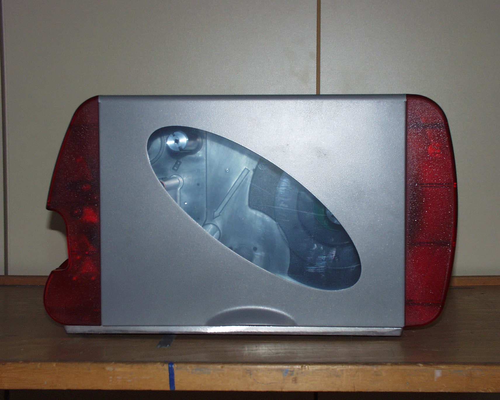
S9LAP44-AP54
Jul 19, 2005RFID Label Printer
Equipment Class
DSS - Part 15 Spread Spectrum Transmitter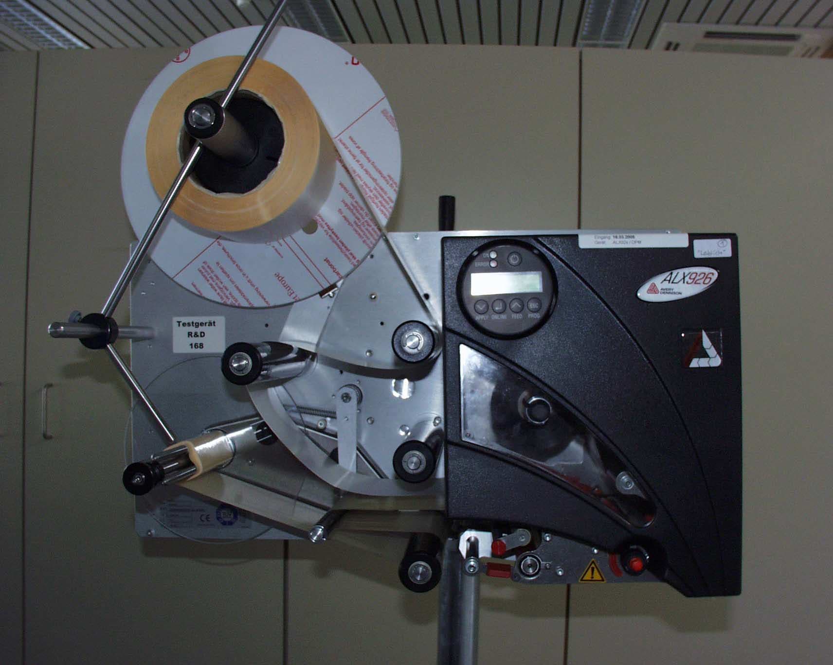
S9LALX92X-DPM-PEM
Jul 19, 2005RFID Label Printer
Equipment Class
DSS - Part 15 Spread Spectrum Transmitter