SDL-PX1XTR1Drill Guide
Hilti Corporation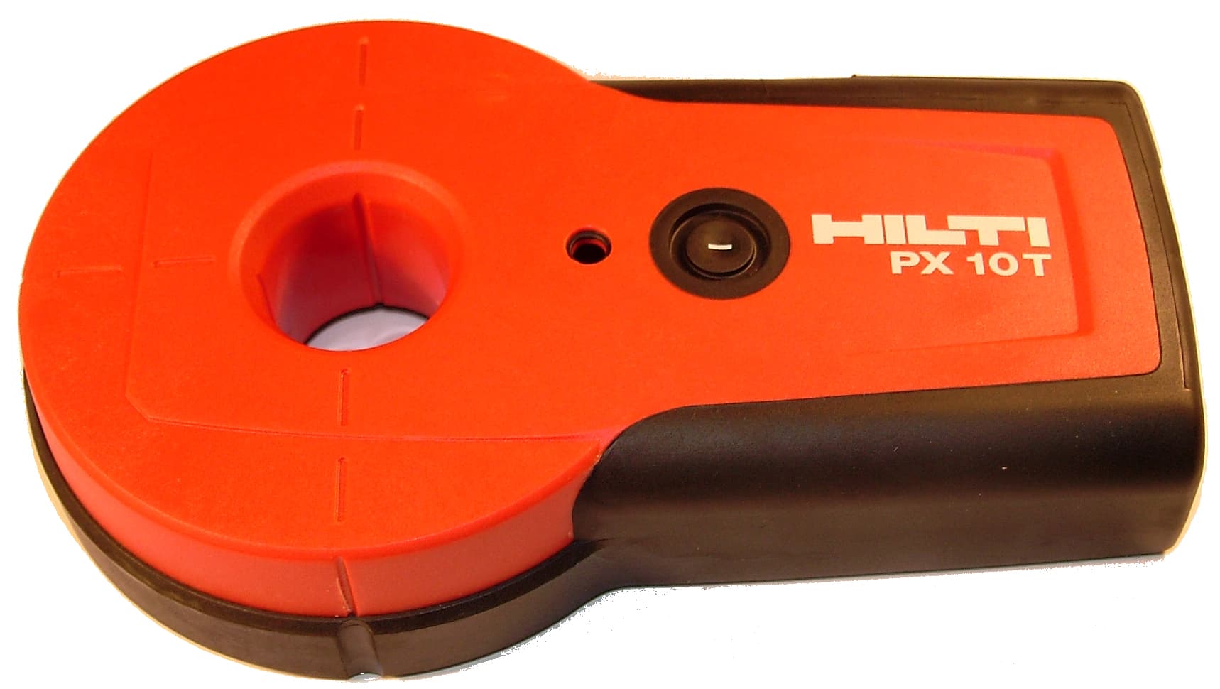
Click to zoom
Application Details
- Equipment Class
- DCD - Part 15 Low Power Transmitter Below 1705 kHz
- Date of Grant
- Feb 08, 2006
- Application Purpose
- Original Equipment
- Date of Application
- Feb 08, 2006
- Equipment Note
- Drill Guide
- Frequency Range
- 0.06550000 - 0.06550000
- Company
- Hilti Corporation
- Country
- Liechtenstein
Documents & Files
Document Text
Text extracted from the exhibit documents filed with the FCC. Open a document above to read the original.
Users Manual
User Manual.doc Seite 1 von 9 PX 10 Transpointer - Operating Instructions ______________________________________________________________________________ It is essential that the operating instructions are read before the tool is used for the first time. Always keep these operating instructions together with the tool. Ensure the operating instructions are with the tool when it is given to other persons. Contents 1. General information 2. Description 3. Tools and accessories 4. Technical data 5. Safety precautions 6. Before use 7. Operation 8. Applications 9. Calibration 10. Care and maintenance 11. Disposal 12. Warranty 13. FCC and IC statements 14. EC declaration of conformity Component parts 1. Transmitter PX 10T 2. On/Off key 3. Status indication light 4. Indentations for adhesive putty 5. Battery compartment 6. Hand strap PDA 60 7. Receiver PX 10R 8. On/Off key 9. Direction arrows 10. Display a. Battery status b. Signal status c. Measuring units d. Distance 11. Marking notch 12. Battery compartment 13. Hand strap PDA 60 14. Slope adapter PXA 70 15. Holder for PX 10R 16. Scale showing angle of measurement 17. Adjustment thread 18. Reference point 19. Marking notch 1. General information 1.1 Safety notices and their meaning -WARNING- The word WARNING is used to draw attention to a potentially dangerous situation which could lead to severe personal injury or death. -CAUTION- This word indicates a possible hazardous situation which could result in slight bodily injuries or damage to property. Gelöscht: E_Transpointer_PX 10_22.01.06 User Manual.doc Seite 2 von 9 -NOTE- Draws attention to instructions and other useful information. 1.2 Pictograms Warning signs Symbols 1 These numbers refer to the corresponding illustrations. The illustrations can be found in the fold-out cover pages. Keep these pages open when studying the operating instructions. In these operating instructions, the PX 10 Transpointer is referred in it’s two components. The PX 10T as the “transmitter”. The PX 10R as the “receiver”. Or in general as the “tools”. 1.3 Location of the identification data on the tools The type designation and serial number can be found on the type designation plate on the tool. Make a note of this data in your operating instructions and always refer to it when making an enquiry to your Hilti representative or service department. Type: PX 10T Serial no.: Type: PX 10R Serial no.: 2. Description The PX 10 is a system built up of a transmitter and a receiver. The receiver is used to find the direction the transmitter is pointing, and for finding the distance between the two devices. 2.1 Intended use The Transpointer is used to align the receiver position to the preset transmitter position. The system is capable of this function through walls and ceilings, as well as determining the distance between the devices. The operator can transfer points from one side of a wall to another, and determine at the same time the wall thickness. This helps: - to check where a marked entry point for a through hole will exit. - to determine what length drill bit or core is needed - to transfer positions The Transpointer may also be used in conjunction with the slope adapter to: - To find a exit point from a given reference point and angle - Find the angle between two points 2.2 Items supplied 1 PX 10T transmitter 1 PX 10R receiver 2 PDA 60 hand straps 2 Type 9 volt batteries 1 PUA 91 adhesive putty (general) 1 PUA 92 adhesive strips (interior) 1 Operating instructions 2 Producer certificate 1 Hilti case 1 PXA 70 slope adapter* 10 PUA 70 markers* * depending on the version purchased these items, may not be included in the supplied items. Gelöscht: E_Transpointer_PX 10_22.01.06 User Manual.doc Seite 3 von 9 2.3 Measuring principle The transmitter generates a magnetic field. This field can penetrate bricks, wood, concrete, and concrete with metal reinforcement. The field is however affected by metal. Whilst normal reinforcement in concrete is not a problem, welded reinforcement, reinforcement mesh, flat metal sheet or massive metal beams can have a considerably negative effect on the system performance. The receiver is calibrated to find the center point of the projected field and to determine the distance by the measurement of the strength of the magnetic field between the two tools. The slope adapter has been developed in conjunction with the Transpointer, so that the magnetic fields can also be measured when the devices are inclined to each other. 3. Accessories Adhesive putty PUA 91 Adhesive strips PUA 92 Hand strap PDA 60 Slope adapter PXA 70 Markers PUA 70 4. Technical data Position accuracy, typical ±8mm for every 200mm of thickness up to 1m at 21°C (+70°F) Thickness accuracy, typical ±5% of thickness up to 1m at 21°C (+70°F) (excluding slope adapter) Position accuracy, maximum ±2mm for every 200mm of thickness up to 1m at 21°C (+70°F) without the influence of metal Thickness accuracy, maximum ±5% of thickness up to 1m at 21°C (+70°F) without the influence of metal (excluding slope adapter) Operating range (typical) 50mm to 1.35m (2” to 4’ 5”) Operating temperature (PX 10T, PX 10R, PUA 91) -10°C to +55°C (+14°F to +131°F) Operating temperature (PUA 92) +10°C to 40°C (+50°F to +104°F) Storage temperature -25°C to +70°C (-13°F to +158°F) Power supply (PX 10T, PX 10R) 1 x size E-Block battery (9 V) Life time (PX 10T, PX 10R) 17 hours at +21°C (+70°F) Protection class (excluding battery compartment) IP 56 Protected against dust and powerful water jets Weight with battery (PX 10T) 190g (0.42lb) Weight with battery (PX 10R) 230g (0.51lb) Dimensions (PX 10T) 160mm x 95mm x 33mm (6.3” x 3.8” x 1.3”) Dimensions (PX 10R) 210mm x 95mm x 33mm (8.3” x 3.8” x 1.3”) Slope adapter range 90° to 45° (0° to 45°) Slope adapter maximal accuracy ±2° -CAUTION- The accuracy can be strongly degraded if welded metal reinforcement or metal sheets or supports are close to the tools. The thickness measurement in case of welded reinforcement is…
Text truncated - open the document above for the full version.
ID Label/Location Info
Made in Germany Hilti = registered trademark of Hilti Corporation, Schaan, LI PX 10 T Power: 9V nominal / 30mA Serial No.: Manufact.: Item No.: FCC ID:SDL-PX1XTR1 IC: 5228A-PX1XR1 N4025 This device complies with Part 15 of the FCC Rules. Operation is subject to the following two conditions: (1) this device may not cause harmful interference, and, (2) this device must accept any interference received, including interference that may cause undesired operation. 50mm 25mm 11mm 7,85mm 10mm 3,9mm R 1,5mm 319973 FCC ID: SDL-PX1XTR1 mikes-testingpartners gmbh File No. T30369-00-00HU, page 6 of 26 Ohmstrasse 2-4 x 94342 Strasskirchen Tel.:+49(0)9424-94810 x Fax:+49(0)9424-9481240 Rev. No. 1.1 Transmitter
Internal Photos
FCC ID: SDL-PX1XTR1 mikes-testingpartners gmbh File No. T30369-00-00HU, page 7 of 26 Ohmstrasse 2-4 x 94342 Strasskirchen Tel.:+49(0)9424-94810 x Fax:+49(0)9424-9481240 Rev. No. 1.1 Transmitter FCC ID: SDL-PX1XTR1 mikes-testingpartners gmbh File No. T30369-00-00HU, page 8 of 26 Ohmstrasse 2-4 x 94342 Strasskirchen Tel.:+49(0)9424-94810 x Fax:+49(0)9424-9481240 Rev. No. 1.1 Transmitter FCC ID: SDL-PX1XTR1 mikes-testingpartners gmbh File No. T30369-00-00HU, page 9 of 26 Ohmstrasse 2-4 x 94342 Strasskirchen Tel.:+49(0)9424-94810 x Fax:+49(0)9424-9481240 Rev. No. 1.1 Transmitter
Test Report
FCC ID: SDL-PX1XTR1 mikes-testingpartners gmbh File No. T30369-00-00HU, page 1 of 26 Ohmstrasse 2-4 x 94342 Strasskirchen Tel.:+49(0)9424-94810 x Fax:+49(0)9424-9481240 Rev. No. 1.1 EMI -- T E S T R E P O R T Test Report No. : T30369-00-00HU 21. December 2005 ______________________________________________________________________________________________ Date of issue Type / Model Name : PX 10 T (Transmitter), PX 10 R (Receiver) Product Description : Drill Guide Applicant : Hilti AG Address : Feldkircherstrasse 100 FL-9494 Schaan, Fürstentum Liechtenstein Manufacturer : Plättner Elektronik GmbH Address : Lerchenbreite 8 D-38889 Blankenburg Licence holder : Hilti AG Address : Feldkircherstrasse 100 FL-9494 Schaan, Fürstentum Liechtenstein Test Result according to the standards listed in clause 1 test standards: POSITIVE The test report merely corresponds to the test sample. It is not permitted to copy extracts of these test results without the written permission of the test DAT-P-207/05-00 laboratory. FCC ID: SDL-PX1XTR1 mikes-testingpartners gmbh File No. T30369-00-00HU, page 2 of 26 Ohmstrasse 2-4 x 94342 Strasskirchen Tel.:+49(0)9424-94810 x Fax:+49(0)9424-9481240 Rev. No. 1.1 Contents 1 TEST STANDARDS 3 2 SUMMARY 4 3 EQUIPMENT UNDER TEST 5 3.1 PHOTO DOCUMENTATION OF THE EUT 5 3.2 POWER SUPPLY SYSTEM UTILISED 14 3.3 SHORT DESCRIPTION OF THE EQUIPMENT UNDER TEST (EUT) 14 4 TEST ENVIRONMENT 15 4.1 ADDRESS OF THE TEST LABORATORY 15 4.2 ENVIRONMENTAL CONDITIONS 15 4.3 STATEMENT OF THE MEASUREMENT UNCERTAINTY 15 4.4 MEASUREMENT PROTOCOL FOR FCC, VCCI AND AUSTEL 15 5 TEST CONDITIONS AND RESULTS 17 5.1 CONDUCTED EMISSIONS 17 5.2 FIELD STRENGTH OF THE FUNDAMENTAL WAVE 18 5.3 TRANSMITTER SPURIOUS EMISSIONS (MAGNECTIC FIELD) 9 KHZ – 30 MHZ 20 5.4 EMISSION BANDWIDTH 23 5.5 RECEIVER SPURIOUS EMISSIONS (MAGNECTIC FIELD) 9 KHZ – 30 MHZ 24 6 USED TEST EQUIPMENT AND ACCESSORIES 26 FCC ID: SDL-PX1XTR1 mikes-testingpartners gmbh File No. T30369-00-00HU, page 3 of 26 Ohmstrasse 2-4 x 94342 Strasskirchen Tel.:+49(0)9424-94810 x Fax:+49(0)9424-9481240 Rev. No. 1.1 1 TEST STANDARDS The tests were performed according to following standards: FCC Rules and Regulations Part 15 Subpart C- Intentional Radiators (October 01, 2004) Part 15, Subpart C, Section 15.209(a) Radiated emissions, general requirements FCC ID: SDL-PX1XTR1 mikes-testingpartners gmbh File No. T30369-00-00HU, page 4 of 26 Ohmstrasse 2-4 x 94342 Strasskirchen Tel.:+49(0)9424-94810 x Fax:+49(0)9424-9481240 Rev. No. 1.1 2 SUMMARY GENERAL REMARKS: The EuT consists of 1 Transmitter and 1 Receiver. They work in direct vicinity. Transmitter and receiver have been measured separately. Carrier frequency: 65.536 kHz FINAL ASSESSMENT: The equipment under test fulfills the EMI requirements cited in clause 1 test standards. Date of receipt of test sample : acc. to storage records Testing commenced on : 23. November 2005 Testing concluded on : 02. December 2005 Checked by: Tested by: Klaus Gegenfurtner Dipl.-Ing.(FH) Manager: Radio Group Markus Huber FCC ID: SDL-PX1XTR1 mikes-testingpartners gmbh File No. T30369-00-00HU, page 14 of 26 Ohmstrasse 2-4 x 94342 Strasskirchen Tel.:+49(0)9424-94810 x Fax:+49(0)9424-9481240 Rev. No. 1.1 3.2 Power supply system utilised Power supply voltage : Transmitter: 9 VDC, Receiver: 9 VDC 3.3 Short description of the Equipment under Test (EuT) The transmitter generates two different magnetic alternating fields when activated. These fields are used by the receiver for alignment with the transmitter. Number of tested samples: 2 Serial number: Prototype EuT operation mode: The equipment under test was operated during the measurement under the following conditions: - Data transmission between TX and RX - Standby mode EuT configuration: (The CDF filled by the applicant can be viewed at the test laboratory.) The following peripheral devices and interface cables were connected during the measurements: - Model : - Model : - Model : - Model : - Model : - Model : FCC ID: SDL-PX1XTR1 mikes-testingpartners gmbh File No. T30369-00-00HU, page 15 of 26 Ohmstrasse 2-4 x 94342 Strasskirchen Tel.:+49(0)9424-94810 x Fax:+49(0)9424-9481240 Rev. No. 1.1 4 TEST ENVIRONMENT 4.1 Address of the test laboratory mikes-testingpartners gmbh Ohmstrasse 2-4 94342 Strasskirchen Germany 4.2 Environmental conditions During the measurement the environmental conditions were within the listed ranges: Temperature: 15-35 ° C Humidity: 30-60 % Atmospheric pressure: 86-106 kPa 4.3 Statement of the measurement uncertainty The data and results referenced in this document are true and accurate. The reader is cautioned that there may be errors within the calibration limits of the equipment and facilities. The measurement uncertainty was calculated for all measurements listed in this test report acc. to CISPR 16-4-2 /11.2003 „Uncertainties, statistics and limit modelling – Uncertainty in EMC measurements“ and is documented in the quality system acc. to DIN EN ISO/IEC 17025. Furthermore, component and process variability of devices similar to that tested may result in additional deviation. The manufacturer has the sole responsibility of continued compliance of the device. 4.4 Measurement Protocol for FCC, VCCI and AUSTEL 4.4.1 GENERAL INFORMATION 4.4.1.1 Test Methodology Conducted and radiated disturbance testing is performed according to the procedures in International Special Committee on Radio Interference (CISPR) Publication 22 (1997), European Standard EN 55022 and Australian Standard AS 3548 (which are based on CISPR 22). The Japanese standard, "Voluntary Control Council for Interference (VCCI) by Data Processing Equipment and Electronic Office Machines, Technical Requirements" is technically equivalent to CISPR 22 (1997). For official compliance, a conformance report must be sent to and accepted by the VCCI. In compliance with FCC Docket 92-152, "Harmonization of Rules for Digital Devices Incorporate International Standards", testing for FCC compliance may be done fol…
Text truncated - open the document above for the full version.
Test Setup Photos
FCC ID: SDL-PX1XTR1 mikes-testingpartners gmbh File No. T30369-00-00HU, page 18 of 26 Ohmstrasse 2-4 x 94342 Strasskirchen Tel.:+49(0)9424-94810 x Fax:+49(0)9424-9481240 Rev. No. 1.1 5.2 Field strength of the fundamental wave For test instruments and accessories used see section 6 Part CPR 1. 5.2.1 Description of the test location Test location: OATS1 Test distance: 3 metres 5.2.2 Photo documentation of the test set-up FCC ID: SDL-PX1XTR1 mikes-testingpartners gmbh File No. T30369-00-00HU, page 20 of 26 Ohmstrasse 2-4 x 94342 Strasskirchen Tel.:+49(0)9424-94810 x Fax:+49(0)9424-9481240 Rev. No. 1.1 5.3 Transmitter Spurious emissions (Magnectic field) 9 kHz – 30 MHz For test instruments and accessories used see section 6 Part SER 1. 5.3.1 Description of the test location Test location: OATS1 Test distance: 3 metres 5.3.2 Photo documentation of the test set-up FCC ID: SDL-PX1XTR1 mikes-testingpartners gmbh File No. T30369-00-00HU, page 23 of 26 Ohmstrasse 2-4 x 94342 Strasskirchen Tel.:+49(0)9424-94810 x Fax:+49(0)9424-9481240 Rev. No. 1.1 5.4 Emission Bandwidth For test instruments and accessories used see section 6 Part MB. 5.4.1 Description of the test location Test location: AREA4 5.4.2 Photo documentation of the test set-up 5.4.3 Test protocol Emission Bandwidth plot Ref -5 dBmAtt 30 dB A 5 kHz/Center 65.6 kHzSpan 50 kHz SWT 50 ms 1 PK VIEW RBW 1 kHz VBW 3 kHz PRN -100 -90 -80 -70 -60 -50 -40 -30 -20 -10 1 Marker 1 [T1 ] -10.90 dBm 65.600000000 kHz 2 Marker 2 [T1 ] -31.56 dBm 60.500000000 kHz 3 Marker 3 [T1 ] -30.51 dBm 70.700000000 kHz D1 -30.9 dBm Date: 24.NOV.2005 10:49:14 FCC ID: SDL-PX1XTR1 mikes-testingpartners gmbh File No. T30369-00-00HU, page 24 of 26 Ohmstrasse 2-4 x 94342 Strasskirchen Tel.:+49(0)9424-94810 x Fax:+49(0)9424-9481240 Rev. No. 1.1 5.5 Receiver Spurious emissions (Magnectic field) 9 kHz – 30 MHz For test instruments and accessories used see section 6 Part SER 1. 5.5.1 Description of the test location Test location: OATS1 Test distance: 3 metres 5.5.2 Photo documentation of the test set-up
Contact Information
Applicant
Ulrich Betten
Test Firm
CSA Group Bayern GmbHThomas Weise
Technical Specifications
| # | Rule Parts | Frequency Range | Power Output |
|---|---|---|---|
| 1 | 15C | 0.0655 MHz - 0.0655 MHz | - |
Other Applications from Hilti Corporation

SDL-PM50A
Aug 21, 2026Auto-align multi-line laser
Equipment Class
DTS - Digital Transmission System
SDL-PMA50
Aug 21, 2026Laser receiver
Equipment Class
DTS - Digital Transmission System
SDL-PS85R01
Mar 27, 2023Ultra-Wideband Wallscanner
Equipment Class
UWB - Ultra Wideband Transmitter
SDL-PR5XM
Jan 23, 2020BLE Board
Equipment Class
DTS - Digital Transmission System
SDL-GXR01
Jul 02, 2015inductive application
Equipment Class
DXX - Part 15 Low Power Communication Device Transmitter