SDN-265B-B021008Bluetooth Clock Radio
Tonika Electronics Technology (Shenzhen) Co., Ltd.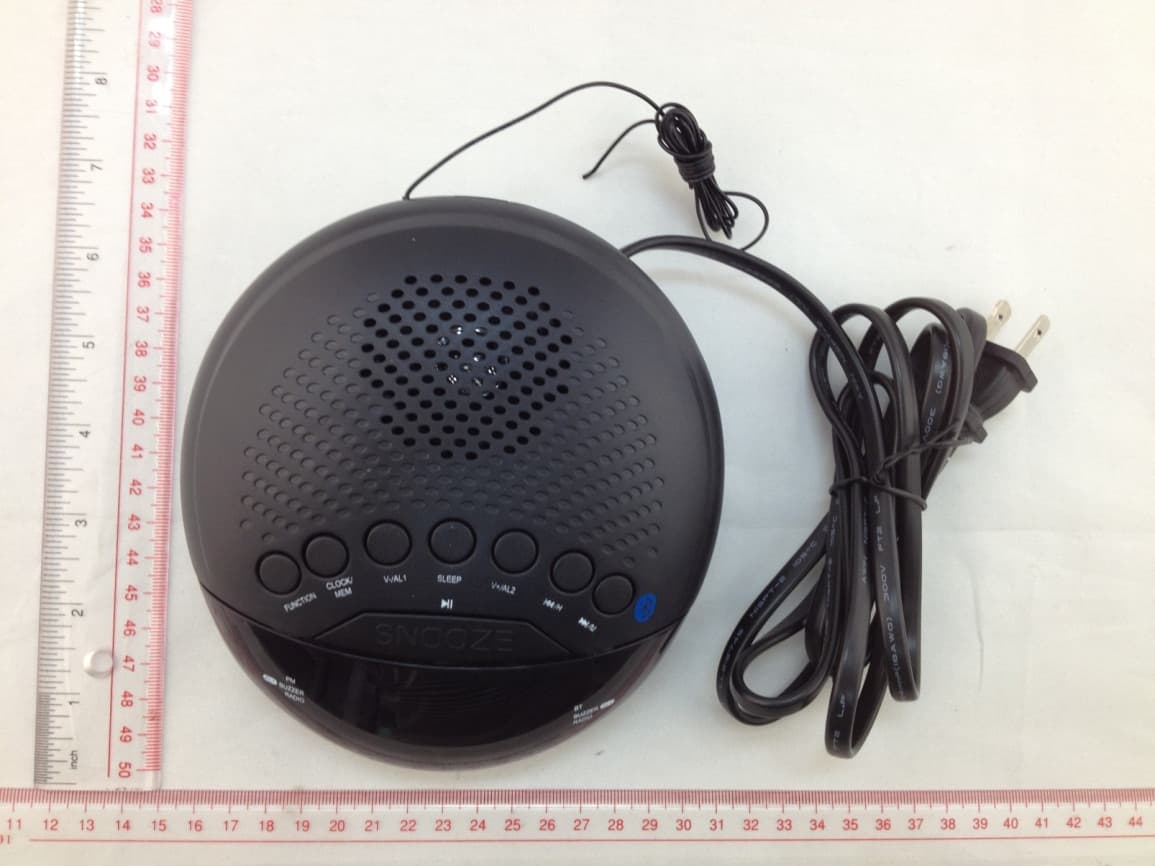
Click to zoom
Application Details
- Equipment Class
- DSS - Part 15 Spread Spectrum Transmitter
- Date of Grant
- Aug 28, 2014
- Application Purpose
- Original Equipment
- Date of Application
- Aug 28, 2014
- Equipment Note
- Bluetooth Clock Radio
- Frequency Range
- 2402.00000000 - 2480.00000000
- Country
- China
Documents & Files
Document Text
Text extracted from the exhibit documents filed with the FCC. Open a document above to read the original.
Users Manual
Snooze: The alarm can be temporarily turned off manually by pressing the /SNOOZE Button; the alarm will turn back on automatically nine (9) minutes later. This feature can be repeated until the FUNCTION Selector was pressed. 1. PM Indicator 2. AL (Alarm) 1 BUZZER Indicator 3. AL (Alarm) 1 RADIO Indicator 4. BT Indicator 5. AL (Alarm) 2 BUZZER Indicator 6. AL (Alarm) 2 RADIO Indicator 7. FUNCTION Selector 8. CLOCK/MEM (Memory) Button 9. V (Volume) -/ AL 1 (Alarm 1 set) Button 10. SLEEP Button 11. V (Volume) +/ AL 2 (Alarm 2 set) Button 12. /H (Skip Backward/Hour set) Button 13. /M (Skip Forward/Minute set) Button 14. (Play/Pause)/SNOOZE Button 15. AC Power Cord 16. FM Antenna 17. Battery Door (On the bottom) Alarm setting Alarm 1 setting: 1. Make sure the unit is in Radio/BT off mode before setting. 2. Press and hold the V-/AL 1 Button until Alarm 1 time appear on the display and blinking. 3. Press the /H Button repeatedly to set the hour of alarm 1. (Make sure the PM Indicator on the display is light if the alarm time is PM and not light if the alarm time is AM). 4. Press the /M Button repeatedly to set the minute of alarm 1. 5. Press the V-/AL 1 Button to save the settings and exit. 6. Press the V-/AL 1 Button repeatedly to set the wake up mode to Buzzer (AL 1 BUZZER Indicator will light) or radio (AL 1 RADIO Indicator will light). Note: If Radio mode is selected, received the desired radio station and set the volume to desired level before activated the alarm. Otherwise, no sound or sound weak when alarm goes off. Alarm 2 setting: Same as above alarm 1 settings. But, press the V+/AL 2 Button instead of V-/AL 1 Button. Shut off alarm: ● When alarm goes off, press the FUNCTION Selector to turn it off, the alarm will reset for next day. ● To turn off the alarm completely (not reset for next day). Press the V-/AL 1 Button (V+-/AL 2 Button for alarm 2) repeatedly until all alarm indicators turned off. In first time use or re-pairing to new BT Device, pairing the unit to external BT Device as below: 1. Press and hold the FUNCTION Selector to turn on Radio/BT (Blue Tooth). 2. Press the Radio FUNCTION Selector repeatedly until “bt” appear on the display. The BT Indicator will light and blinking. 3. Power on the external BT Device and enter to searching mode. Start pairing as the on screen instructions on the external BT Device. After paired, the BT Indicator will stop blinking. (For details pairing procedures, please refer to the user’s manual of your BT Device). Notes: ● When the external BT player searched the unit, our model number “CR41483” will appear on the external BT Device’s display. ● Pairing code “0000” or “1234” may need to enter. Normal operation after pairing: 1. Turn on the BT function of the external BT Device. 2. Press and hold the FUNCTION Selector to turn on Radio/BT (Blue Tooth). 3. Press the FUNCTION Selector repeatedly until “bt” appears on the display. The BT Indicator will light and blinking. Wait until the BT Indicator stop blinking. (It needs a few seconds). 4. Plays the music in the connected BT Device as usual. 5. During playback: ● Press the V-/AL 1 or V+/AL 2 Button to adjust volume level. ● Press the /H or /M Buttons repeatedly to skip the tracks. ● Press the /SNOOZE Button to pause, press again to resume normal playback. 6. When finished listening, press and hold the FUNCTION Selector approximate 1 second to turn off the Radio/BT. Sleep: In Radio or BT power on mode, press the SLEEP Button to activate the sleep function, the time of sleep timer will appear on the display. Press the button repeatedly to set the sleep timer to 10 – 90 minutes as desire. To turn off the sleep timer before time up, press and hold FUNCTION Selector to turn it off. This model is equipped with non-skid rubber ‘feet’ to prevent the product from moving when you operate the controls. These ‘feet’ are made from non-migrating rubber material specially formulated to avoid leaving any marks or stains on your furniture. However certain types of oil based furniture polishes, wood preservatives, or cleaning sprays may cause the rubber ‘feet’ to soften, and leave marks or a rubber residue on the furniture. To prevent any damage to your furniture we strongly recommend that you purchase small self-adhesive felt pads, available at hardware stores and home improvement centers everywhere, and apply these pads to the bottom of the rubber ‘feet’ before you place the product on fine wooden furniture. To set or reset the actual local time: 1. Press and hold the CLOCK/MEM Button until the display is blinking. 2. Press the /H Button repeatedly to set the hour. (Make sure the PM Indicator on the display is light if the time is PM and not light if the time is AM). 3. Press the /M Button repeatedly to set minute. 4. When finished, press the CLOCK/MEM Button to save the settings and exit. The display will stop blinking. Radio reception 1. Press and hold the FUNCTION Selector to turn on Radio/BT (Blue Tooth). 2. Press the FUNCTION Selector repeatedly to select AM; FM or BT as desired. ● If FM is selected, FM frequency 87.5 – 108.0 will appear on the display. ● If AM is selected, AM frequency 520-1710 will appear on the display. ● If BT (Blue Tooth) is selected, “bt” will appear on the display. 5. If AM or FM is selected, press and hold the /H or /M Button until the frequency on the display start running then release the button to search and plays the next (previous) available radio station. Repeat the same procedures until the desired radio station was found and plays. 6. Press the /H or /M Button repeatedly to fine tune. 7. Press the V-/AL 1 or V+/AL 2 Button to adjust volume level. 8. When finished listening, press and hold the FUNCTION Selector approximate 1 second to turn off the Radio/BT. Antenna: FM: The FM Antenna wire in the rear of unit is for radio reception. If reception is weak, unwound and extended the wire or relocation the wire to improve the radio reception. AM: This unit has a build in ferrite r…
Text truncated - open the document above for the full version.
External Photos
ANNEX C EUT PHOTOS C.1 Appearance of the EUT THE FRONT OF EUT THE BACK OF EUT THE DOWN OF EUT THE UP OF EUT THE LEFT OF EUT THE RIGHT OF EUT
ID Label/Location Info
Label and Label Location Label: Label Location:
Internal Photos
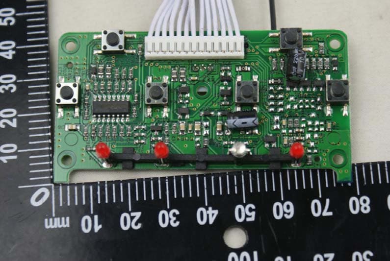
C.2 Inside of the EUT EUT UNCOVER VIEW MAIN BOARD BACK VIEW 1 MAIN BOARD BACK VIEW 2 MAIN BOARD BACK VIEW 3 MAIN BOARD BACK VIEW 4 MAIN BOARD BACK VIEW 4 MAIN BOARD BACK VIEW 5 RF MODULE RF MODULE
Test Report
Report No.: BL-SZ1480058-601 2 Revision History Version Issue Date Revisions Rev. 01 2014.08.27 Initial Issue TABLE OF CONTENTS 1 ADMINISTRATIVE DATA (GENERAL INFORMATION) ........................................................................ 5 1.1 Identification of the Testing Laboratory ............................................................................................ 5 1.2 Identification of the Responsible Testing Location ........................................................................... 5 1.3 Test Environment Condition ............................................................................................................ 5 1.4 Announce ........................................................................................................................................ 6 2 PRODUCT INFORMATION ................................................................................................................... 7 2.1 Applicant ......................................................................................................................................... 7 2.2 Manufacturer ................................................................................................................................... 7 2.3 General Description for Equipment under Test (EUT) ..................................................................... 7 2.4 Technical Information ...................................................................................................................... 7 2.5 Ancillary Equipment ......................................................................................................................... 7 3 SUMMARY OF TEST RESULTS ........................................................................................................... 8 3.1 Test Standards ................................................................................................................................ 8 3.2 Verdict ............................................................................................................................................. 8 4 GENERAL TEST CONFIGURATIONS .................................................................................................. 9 4.1 Test Environments .......................................................................................................................... 9 4.2 Test Equipment List ......................................................................................................................... 9 4.3 Test Configurations ....................................................................................................................... 10 4.4 Description of Test Setup .............................................................................................................. 10 4.4.1 For Antenna Port Test ............................................................................................................ 10 4.4.2 For AC Power Supply Port Test .............................................................................................. 10 4.4.3 For Radiated Test (Below 30MHz) .......................................................................................... 11 4.4.4 For Radiated Test (30MHz-1GHz) .......................................................................................... 11 4.4.5 For Radiated Test (Above 1GHz) ........................................................................................... 12 4.5 Test Conditions ............................................................................................................................. 12 Report No.: BL-SZ1480058-601 3 5 TEST ITEMS ....................................................................................................................................... 13 5.1 Antenna Requirements .................................................................................................................. 13 5.1. 1 Standard Applicable ............................................................................................................... 13 5.1.2 Antenna Anti-Replacement Construction ................................................................................ 13 5.1.3 Antenna Gain ......................................................................................................................... 13 5.2 Number of Hopping Frequency ..................................................................................................... 14 5.2.1 Limit ........................................................................................................................................ 14 5.2.2 Test Procedure ....................................................................................................................... 14 5.3 Peak Output Power ....................................................................................................................... 15 5.3.1 Test Limit ................................................................................................................................ 15 5.3.2 Test Procedure ....................................................................................................................... 15 5.4 Occupied Bandwidth ..................................................................................................................... 16 5.4.1 Limit ........................................................................................................................................ 16 5.4.2 Test Procedure ....................................................................................................................... 16 5.5 Carr ier Frequency Separation ....................................................................................................... 17 5.5.1 Limit ........................................................................................................................................ 1…
Text truncated - open the document above for the full version.
Test Setup Photos
ANNEX B TEST SETUP PHOTOS B.1 Conducted Test Photo B.2 Conducted Emissions Test Photo B.3 Radiated Test Photo Below 30MHz 30MHz to 1GHz Above 1GHz
Contact Information
Applicant
XIANG DONG(Sales Manager)
Test Firm
Shenzhen BALUN Technology Co.,Ltd.Xuewen Wu
Technical Specifications
| # | Rule Parts | Frequency Range | Power Output |
|---|---|---|---|
| 1 | 15C | 2.40 GHz - 2.48 GHz | 2.07 mW |
Other Applications from Tonika Electronics Technology (Shenzhen) Co., Ltd.
SDNTA-320B-01
Sep 08, 2015Bluetooth Speaker
Equipment Class
DSS - Part 15 Spread Spectrum Transmitter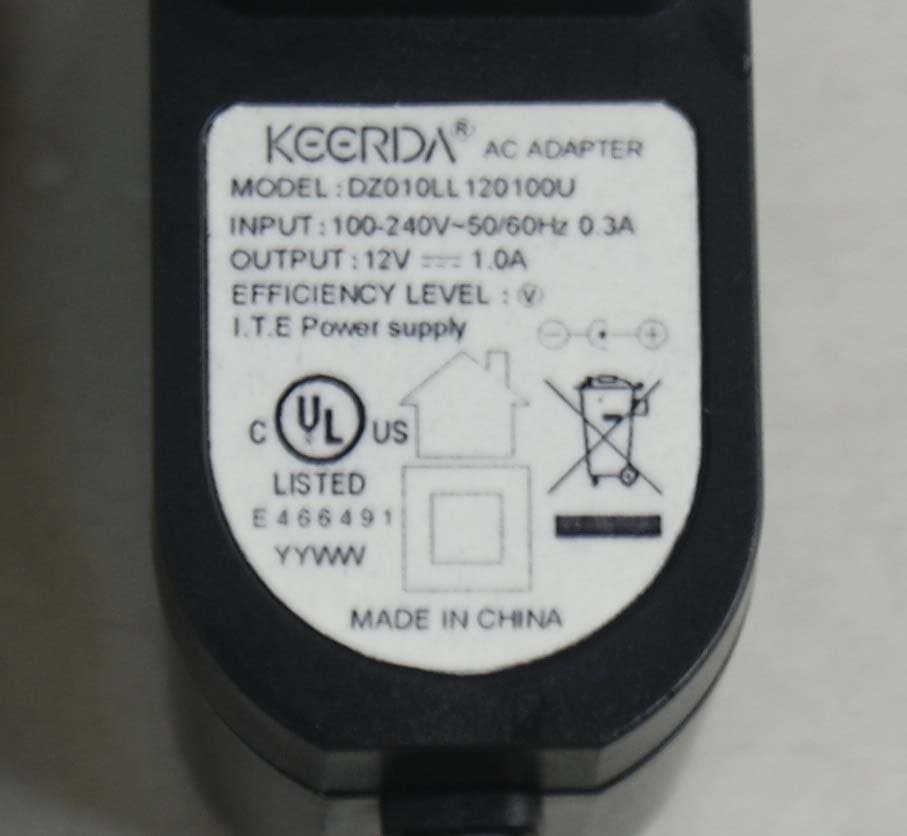
SDNTA-304DG-01
Aug 20, 2015Bluetooth Speaker
Equipment Class
DSS - Part 15 Spread Spectrum Transmitter
SDNTA-483-01
Aug 09, 2015Bluetooth Speaker
Equipment Class
DSS - Part 15 Spread Spectrum Transmitter
SDNTA-479-01
Jul 20, 2015BLUETOOTH WIRELESS TECHNOLOGY SPEAKER
Equipment Class
DSS - Part 15 Spread Spectrum Transmitter
SDNTA-440-01
May 20, 2015WATER DANCING TOWER SPEAKER
Equipment Class
DSS - Part 15 Spread Spectrum Transmitter