SFISZ100SCHOOL ZONE FLASHING BEACON
JSF Technologies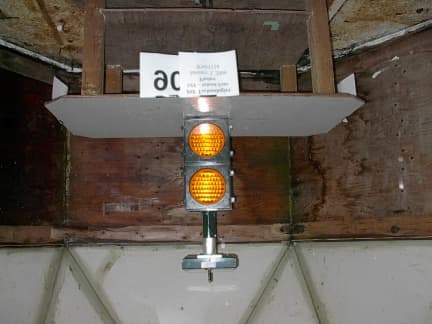
Click to zoom
Application Details
- Equipment Class
- DSS - Part 15 Spread Spectrum Transmitter
- Date of Grant
- May 18, 2006
- Application Purpose
- Original Equipment
- Date of Application
- May 18, 2006
- Equipment Note
- SCHOOL ZONE FLASHING BEACON
- Frequency Range
- 902.50000000 - 927.50000000
- Company
- JSF Technologies
- Country
- Canada
Documents & Files
Document Text
Text extracted from the exhibit documents filed with the FCC. Open a document above to read the original.
Users Manual
School Zone Flashing Beacon Description and Installation Instructions Introduction JSF Technologies’ School Zone Flashing Beacon is the most efficient system available on the market. Being solar powered, the system installs in minutes on any pole with no electrical connection. The school district is able to create an annual usage schedule or make immediate changes to the schedule from any location over the Internet. The schedule is transmitted wirelessly to the units with the click of a mouse and the user receives e- mail confirmation that the schedule was received. The system is made up of one Primary unit (SZ 100) and any number of Satellite AB500 units ( FCC ID:SFIAB500) for each school. The Primary receives and stores an entire years schedule information via wireless “Narrow-Band PCS” communications across North America. Each time the system is scheduled to flash, the Primary transmits “Turn On” and “Turn Off” messages to the Satellites, via 902-928 MHz spread spectrum radio signal within a range of 1 kilometer. Each field adjustable network of school zone flashers has 8 addresses to ensure that systems at adjacent schools do not interfere with eachother. The system is available with 8” or 12” signal lights. Each School Zone (SZ100) unit consists of key parts: 1. The Solar Panel housing that contains • Solar Panels: 4.5W, 6V, 12 ¾” x 5 1/8” per solar panel. Multiple panels used on some models. • Antennas: Primary contains two antennas, Satellites contain one antenna. SZ100 units utilize a unique reverse polarity SMA connector. The antenna is ANT-916-CW-HD ¼ wave Whip from Linx Technologies. Gain of 3dBi. Primary and Satellite beacons communicate in a local RF network situated up to 1000 metres from eachother. • Batteries: 2V, 25Ah, BC cell. Multiple batteries used on some models. • Control circuitry. Satellites contain one control box. (It is a actually standard AB500 Active Beacon unit that are working only in receive mode.) Primary contains two control boxes. One of them is a standard AB500 module and the second one is a School Zone Flasher unit that has a FCC approved Advantra pager module and a CC1010 based spread spectrum 900Mhz transmitter. When SZ100 unit transmits the signals ON or OFF the AB500 receives the signal through the leakage of RF energy from SZ100 unit. The satellite units receive the signal through the antennas. The Printed Circuit Board (SZ100) controller, which includes a CC1010 complete RF System-on-Chip solution, Narrow-Band PCS module, real time clock (RTC) and memory chip. Memory holds a one-year school schedule. The memory can be transferred through a serial port or by the Narrow-Band PCS system. The CC1010 integrates a low- power 300-to-1000 MHz RF transceiver and an 8051-compatible micro-controller. The PCB is installed inside of aluminum housing to reduce EMI. Switches installed on the PCB allow the installer to configure the network address and LED flash pattern. DC-to-DC circuitry converts energy from Batteries, Solar Panels to provide voltage levels compatible with the multiple LED Arrays and battery charging. The CC1010 microcontroller runs on two clock frequencies 32.768 kHz and 14.7456 MHz and controls all functions required to integrate RF communication, charging and LED flashing. The CC1010 is equipped with fully programmable, fast-settling frequency synthesizer. The two frequency registers are designed such that the “next” frequency can be programmed while the “present” frequency is used. The switching between the two frequencies is done through the special register. During synchronization when Rx receives a “right” signal it knows what the next frequency will be looking at the frequency table. The receiver and the transceiver from the moment of the capturing synchronously follow the frequency table. The 51 frequencies are used in a unique predefined pseudo-random sequence. In the simple example below, the five frequencies are used in the sequence 902.5, 914.0, 914.5, 910.0, 919.5 MHz. For communication to take place, the transmitter and receiver must use the same frequency: 902.5MHz 914MHz 914.5MHz 910MHz 919.5MHz 910.5MHz 913.5MHz 925MHz 911.5MHz 912MHz 917.5MHz 907.5MHz 903.5MHz 927MHz 926MHz 922MHz 909.5MHz 905.5MHz 919MHz 911MHz 915MHz 913MHz 918.5MHz 925.5MHz 905MHz 909MHz 921.5MHz 915.5MHz 924.5MHz 903MHz 916MHz 904.5MHz 916.5MHz 917MHz 920MHz 918MHz 908.5MHz 923MHz 907MHz 927.5MHz 920.5MHz 921MHz 904MHz 906.5MHz 908MHz 926.5MHz 922.5MHz 906MHz 924MHz 923.5MHz 912.5MHz The receiver IF bandwidth is 175 kHz matching the transmitted signal of 64 kHz-frequency separation. The maximum output power of transmitter is 20dBm. The Primary Beacon is installed on the top of 2 - 3meter pole so the distance between the antenna and people satisfy power RF density limit. Long-life battery capacity. The system is trickle charged during daylight hours, even in cloudy conditions. On a full charge, the system will operate at the rated usage for over one month without any solar charging. 2. One or two individual 8” or 12” light heads: “A” and “B” containing high efficiency LED light modules. The activation signal ON is received by Satellite beacons in the vicinity of the Primary with the same address. The beacons will flash until OFF signal is received. Installation Each unit is packaged in separate boxes, with a number of individual parts: • Bundle of individual batteries • Upper light head “A” with mounting bracket • Lower light head “B” with mounting bracket • Solar panel housing • Light face bonnets 1. We will start by installing the batteries into the Solar Panel Casing on your workbench. Remove the bolts on the solar panel casing and remove the top. Be careful because there are wires from the solar panels on the top of the casing to the control box on the bottom of the casing. Next, pull the batteries, AS A GROUP, out of the battery box. Lay the batteries down flat on your workbench so that you have all batteries in an orderly row. In the middle of the …
Text truncated - open the document above for the full version.
Cover Letter(s)
6771 Kirkpatrick Cres. Saanichton, BC V8M 1Z8 Canada Ph. (250) 544-1440 or 1-800-475-7335 Fax (250) 544-1450 E-mail: [email protected] Website: www.jsfost er.com Date: Dec 31, 2005Federal Communications CommissionAuthorization and Evaluation DivisionConfidentiality Request: JSF Technologies. School Zone Flasher SZ100Pursuant to Sections 0.457 and 0.459 of the Commission’s Rules, JSFTechnologies hereby requests confidential treatment of the informationaccompanying this Application as outlined below: • Schematics,• Block Diagrams,• Operational Descriptions• Product Parts List The above materials contain trade secrets and proprietary information notcustomarily released to the public. The public disclosure of these matters mightbe harmful to JSF Technologies and provide unjustified benefits to ourcompetitors.Sincerely,Jack FosterPresident
ID Label/Location Info
Safety Just Got Easier FCC ID: SFISZ100 IC: 5301A-SZ100 contains: Advantra AR 100 FCC ID: 033AR100 IC: 48A-AR100 "This device complies with Part 15 of the FCC Rules. Operation is subject to the following two conditions: (1) this device may not cause harmful interference, and (2) this device must accept any interference received, including interference that may cause undesired operation." "This device has been tested and complies with the regulations of Industry Canada Technical Standard RSS-210" "This device has been designed to operate with the antennas listed below, and having a maximum gain of 3 dBi. Antennas not included in this list or having a gain greater than 3 dBi are strictly prohibited for use with this device. The required antenna impedance is 50 ohms." Linx Technologies - ANT-916-CW-HD ¼ WAVE WHIP GAIN 3 dBi "To reduce potential radio interference to other users, the antenna type and its gain should be so chosen that the equivalent isotropically radiated power (e.i.r.p.) is not more than that permitted for successful communication." Caution: Changes or modifications to this equipment, not expressly approved by the manufacturer could void the user's authority to operate the equipment. Mdl: S/N: 123 SZ100 0 1 2 3 4 5 6 7 8 9 10 11 12 13 14 15 Network Address
Test Report
EMC Compatibility Testing Report Rev.1.1 JSF Technologies – School Zone Flasher Report Number: 03124 Page 1 of 21 JSF Technologies School Zone Flasher Report of Measurements per Industry Canada RSS-210 Issue 6 Annex 8 and FCC CFR47 Part 15/B; FCC CFR47 Part 15/C – 15.247 Revision 1.1 May 18, 2006 Approved by Checked by Robert Stirling, P.Eng. Date Protocol Datasystems Labs, Abbotsford BC, Canada FCC Registration Number 96437 Industry Canada Registration Number IC3384 EMC Compatibility Testing Report Rev.1.1 JSF Technologies – School Zone Flasher Report Number: 03124 Page 2 of 21 Index Section I: Information for Test Report of Measurements.....................................................................3 Section II: Report of Measurements for IC RSS-210 Iss.6 & FCC CFR47 Part 15/B...........................5 Section III: Report of Measurements for MIC RSS-210 Issue 6 Annex 8 - Emissions Testing .............6 Part 1 - Radiated Emission Testing in Idle and Receive Mode............................................7 Part 2 - Radiated Emissions – Transmit Mode ....................................................................8 Part 3 - Output Power and EIRP Emissions ........................................................................9 Section IV: Report of Measurements for FCC CFR47 Part 15/C.........................................................10 Part 1 - Radiated Emission Testing ...................................................................................11 Part 2 - Antenna Requirement - 15.203.............................................................................12 Part 3 - Frequency Hopping Spread Spectrum Operation - 15.247..................................13 Appendix A: Emission Data and Plots....................................................................................................15 Appendix B: EUT Photos .......................................................................................................................20 EMC Compatibility Testing Report Rev.1.1 JSF Technologies – School Zone Flasher Report Number: 03124 Page 3 of 21 Section I: Information for Test Report of Measurements Testing Details TESTED BY: David Johanson TEST CONDITIONS: Temperature and Humidity: January 3, 2006 5.1 ° C, 53% January 4, 2006 7.5 ° C, 52% January 5, 2006 9.2 ° C, 57% TEST VOLTAGE: 4Vdc via Power supply built from Solar Power Array Test Facilities Protocol Datasystem Inc., Labs 28945 McTavish Rd. Abbotsford BC, Canada, V4X 2E7 FCC Registration Number 96437 Industry Canada Registration Number IC3384 Test Equipment List EMISSIONS: Manufacturer Model Equipment Description Serial No. Last Cal Next Cal HP 85650A CDN Quasi-Peak Adapter 2043A00240 22/03/05 22/03/06 HP 85662A Spectrum Analyzer Display 2318A05184 22/03/05 22/03/06 HP 8566B Spectrum Analyzer RF Section 2241A02102 22/03/05 22/03/06 HP 85685A RF-Preselector 3107A01222 22/03/05 22/03/06 A.H. Systems SAS-200/510 Antenna Log Periodic 761 04/03/05 04/03/06 EMCO 3105 Antenna DRG Horn (Med) 2024 25/02/05 25/02/06 LaPlace Instruments AC1000 Low Distortion Power Source 138041 12/12/05 12/12/06 Thurlby Thandar HA1600 Power and Harmonics Analyzer 140108 13/12/05 13/12/06 EMCO 3825 2 LISN (25A 50ohm 50/250uH 10k-100M) 9509-2470 20/07/05 20/07/06 EMCO 3110B Antenna Biconical (Type 3) 9401-1850 01/03/05 01/03/06 Rhientech Custom Antenna Mast N/A N/A N/A Protocol EMC Custom Turntable N/A N/A N/A Measurement Uncertainty Parameter Uncertainty Radio Frequency ±1 x 10⁻⁵ Total RF power, conducted ±1,5 dB RF power density, conducted ±3 dB spurious emissions, conducted ±3 dB all emissions, radiated ±6 dB temperature ±1 ° C humidity ±5 % DC and low frequency voltages ±3 % EMC Compatibility Testing Report Rev.1.1 JSF Technologies – School Zone Flasher Report Number: 03124 Page 4 of 21 Company Tested: NAME: JSF Technologies ADDRESS: 6771 Kirkpatrick Cres Saanichton, BC V8m 1Z8 CONTACT: Mr. Stan Polyakov EMAIL: spolyakov@jstechnologies NUMBER: 250-544-1440 Equipment Under Test THE TEST SYSTEM: EUT: School Zone Flasher Manufacturer: JSF Technologies Part Number: SZF Serial Number: ENG 001 TEST VOLTAGE: Internal Battery Pack (Solar Panel recharge system) CABLING: Cable Pins Connector Load/Termination Shielded Ferrites Test-Led 2X22 AWG Screw Terminal No No No Test-Switch 2X22 AWG Screw Terminal No No No CONCLUSION: The School Zone Flasher complies with the requirements of FCC CFR47 Part 15/B, FCC CFR47 Part 15/C and Industry Canada RSS-210 Issue 6 Annex 8 a Category I device. EMC Compatibility Testing Report Rev.1.1 JSF Technologies – School Zone Flasher Report Number: 03124 Page 5 of 21 Section II: Report of Measurements for IC RSS-210 Iss.6 & FCC CFR47 Part 15/B This product is License Exempt for both FCC and IC. There is a requirement for this product to be submitted for certification and requires both an FCC ID and an IC ID number to be added to the labels in accordance with FCC CFR47 Part 2 subpart J (2.901 to 2.956) as well as IC Self-Marking and RSS-Gen standards. Markings According to FCC Section 15.19, and ICES 003, a statement similar to the following must be included on an identification label, which also uniquely identifies the manufactured date, either explicitly or through a serial number etc.: "This equipment complies with FCC Rules, Part 15 and Industry Canada's ICES 003 for a Class A Digital Device. Operation is subject to two conditions: 1) This device may not cause harmful interference, and 2) This device must accept any interference that may cause any undesired operation" Additionally, If the manufacturer markets product to Quebec, the following supplemental information should be added to the label: "Cet Apparreil numerique de la Classe A respecte toutes les exigences du Reglement sur le material broilleur du Canada." User Manual Statements According to FCC Section 15.105, the following statement must be included in a prominent location your User's Manual: NOTE: This equipment has been tested and found to compl…
Text truncated - open the document above for the full version.
Contact Information
Applicant
Valerie Foster
Test Firm
Protocol LabsRobert Stirling
Technical Specifications
| # | Rule Parts | Frequency Range | Power Output |
|---|---|---|---|
| 1 | 15C | 902.5 MHz - 927.5 MHz | 100.00 mW |
Other Applications from JSF Technologies
SFIWP5
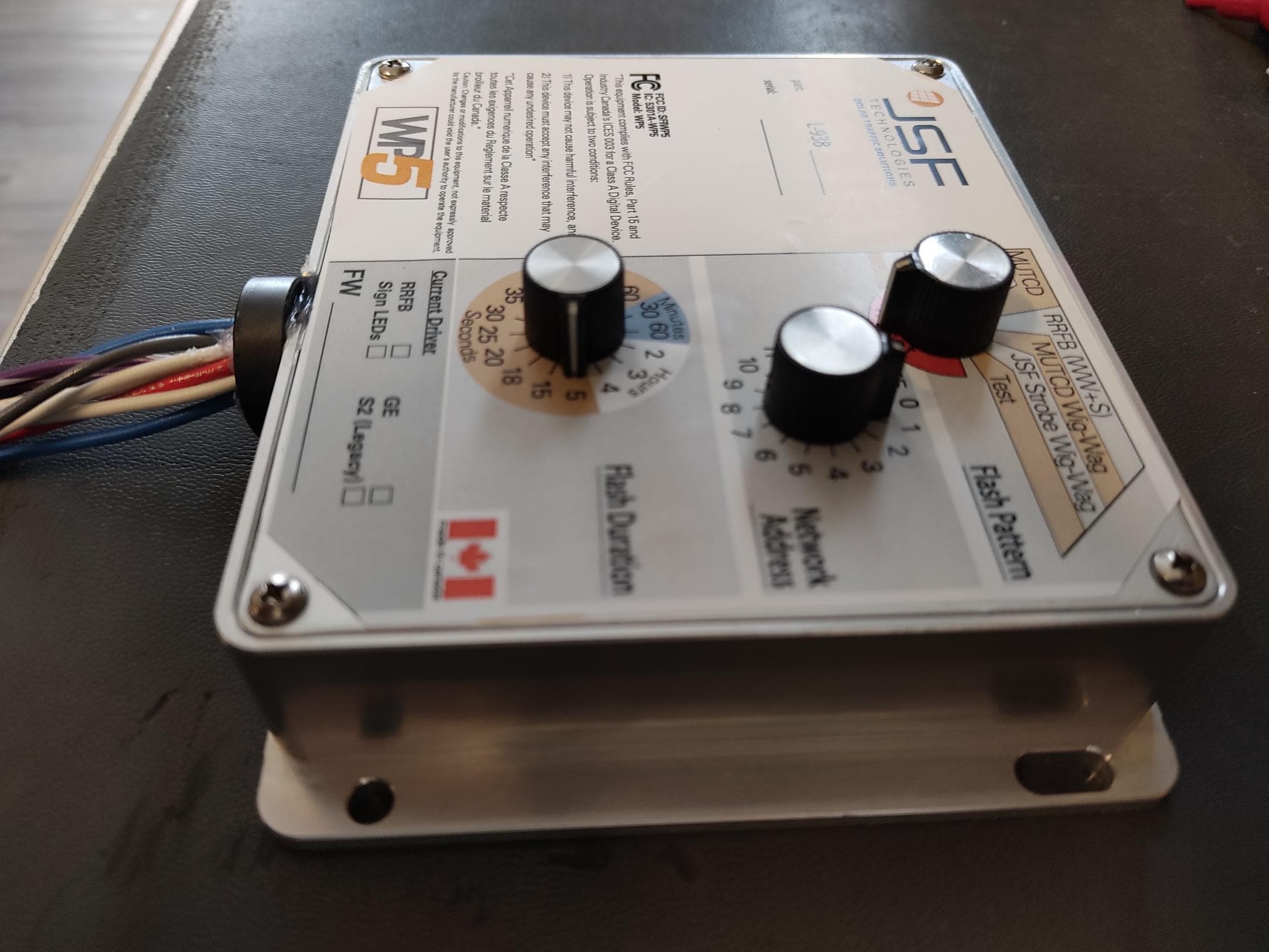
Aug 04, 2020The WP5 is a control module designed for wireless RF communication between other JSFT devices. Applications include crosswalk beacons and warning lights activated via contact-closure relay such as a push-button, sensor, and other devices.
Equipment Class
DXX - Part 15 Low Power Communication Device Transmitter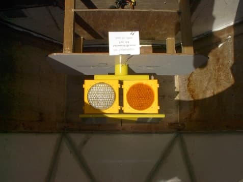
SFIAB500
Sep 01, 2004CROSSWALK-WARNING DEVICE
Equipment Class
DSS - Part 15 Spread Spectrum Transmitter