SFM-SAG-1010802.11bg Wireless Card
SmartAnt Telecom Co., Ltd.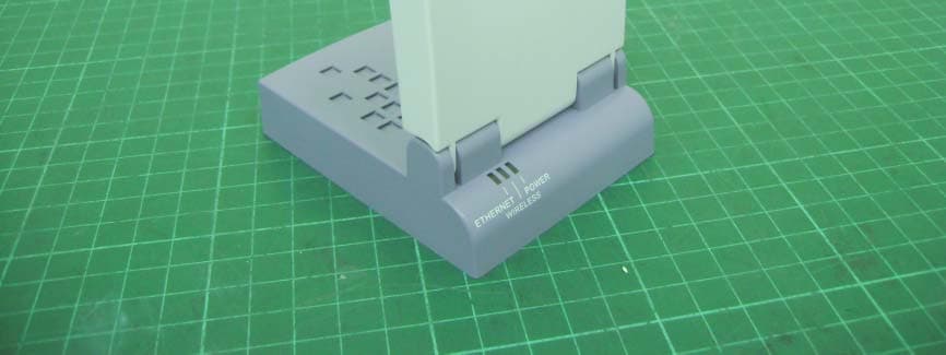
Click to zoom
Application Details
- Equipment Class
- DTS - Digital Transmission System
- Date of Grant
- Oct 25, 2007
- Application Purpose
- Original Equipment
- Date of Application
- Oct 24, 2007
- Equipment Note
- 802.11bg Wireless Card
- Frequency Range
- 2412.00000000 - 2462.00000000
- Company
- SmartAnt Telecom Co., Ltd.
- Country
- Taiwan
Documents & Files
Document Text
Text extracted from the exhibit documents filed with the FCC. Open a document above to read the original.
Users Manual
802.11b/g wireless card SAG-1010 User’s Manual v0.2 SAG-1010 For all the device (15.21) Warning: Changes or modifications to this unit not expressly approved by the party responsible for compliance could void the user authority to operate the equipment. 15.19 (a)(3) This device complies with Part 15 of the FCC Rules. Operation is subject to the following two conditions: (1) this device may not cause harmful interference, and (2) this device must accept any interference received, including interference that may cause undesired operation. The users manual or instruction manual for an intentional or unintentional radiator shall caution the user that changes or modifications not expressly approved by the party responsible for compliance could void the user’s authority to operate the equipment. CAUTION: 1. To comply with FCC RF exposure compliance requirements, a separation distance of at least 20 cm must be maintained between the antenna of this device and all persons. 2. This Transmitter must not be co-located or operating in conjunction with any other antenna or transmitter. Table of Content 1. Product Introduction ........................................................................................... 1 1.1 WELCOME......................................................................................................... 1 1.2 PACKAGE CONTENTS......................................................................................... 1 1.3 FEATURES.......................................................................................................... 2 1.3.1 TOP VIEW................................................................................................... 2 1.3.2 BOTTOM VIEW............................................................................................ 2 1.3.3 REAR VIEW................................................................................................. 3 1.4 LED INDICATORS................................................................................................ 3 1.5 RECOMMENDED NETWORK SETTINGS................................................................. 4 1.5.1 ACCESS POINT MODE.................................................................................. 4 1.5.2 ETHERNET ADAPTER MODE........................................................................ 5 2. Hardware Installation.......................................................................................... 7 2.1 SYSTEM REQUIREMENTS.................................................................................... 7 2.2 DEVICE INSTALLATION...................................................................................... 7 2.2.1 BEFORE YOU PROCEED............................................................................... 7 2.2.2 USING DC POWER........................................................................................ 8 2.2.3 USING USB BUS POWER............................................................................... 8 2.3 PLACEMENT....................................................................................................... 9 2.3.1 WALL MOUNTING....................................................................................... 9 2.3.2 WINDOW MOUNTING.................................................................................. 9 2.4 OPERATING RANGE.......................................................................................... 10 2.4.1 RANGE......................................................................................................10 2.4.2 SITE SURVEY............................................................................................ 10 3. Configuration...................................................................................................... 11 3.1 WEB CONFIGURATION........................................................................................ 11 3.1.1 ADJUSTING THE TCP/IP SETTING............................................................. 11 3.1.2 LAUNCHING THE WEB CONFIGURATION................................................ 13 3.2 CHANGING THE ACCESS POING(AP) CONFIGURATION................................... 13 3.3 CHANGING THE ADAPTER CONFIGURATION.................................................. 24 4. Using the Device ................................................................................................. 29 4.1 USING THE DEVICE IN A LOCAL NETWORK.................................................... 29 4.2 REPLACING THE COMPUTER ETHERNET CABLES........................................... 29 4.3 REPLACINT CABLE CONNECTIONS OF OTHER DEVICES................................. 30 1 1. Product Introduction 1.1. Welcome! Thank you for choosing the SAG-1010 series. The SAG-1010 is a compact easy-to-install Ethernet adapter. Implementing the IEEE 802.11g standard for wireless LAN (WLAN), the SAG-1010 is capable of up to 54Mbps data transmission rate using the Direct Sequence Spread Spectrum (DSSS) and the Orthogonal Frequency Division Multiplexing (OFDM) technologies. The SAG-1010 supports Infrastructure and Ad-hoc modes giving you flexibility on your existing or future wireless network configurations. To provide efficient security to your wireless communication, SAG-1010 comes with a 64-bit/128- bit Wired Equivalent Privacy (WEP) encryption and Wi-Fi Protected Access (WPA) features. With these and many more, SAG-1010 is sure to keep you ahead in the world of wireless computing. 1.2. Package contents Check the following items in your SAG-1010 package. Contact your retailer if any item is damaged or missing. ⊙ Range extension WLAN adapter ⊙ Power adapter ⊙ RJ-45 cable ⊙ USB Cable ⊙ Mounting set ⊙ Quick Installation Guide Unless otherwise specified, the term “device” in this User Guide refers to the SAG-1010. 1.3. Features The SAG-1010 employs the DSSS and OFDM technologies to transmit and receive signals through radio waves on the 2.4 GHz band. Here are other SAG-1010 features: • Re…
Text truncated - open the document above for the full version.
Users Manual
13 3. Configuration RF Channel. Allows you to specify the channel the device uses to communicate with other wireless device(s) in the network. The 802.11g specification supports up to 13 overlapping channels for radio communication. If SAG-1010 is operating in the same area, assign a non-overlapping channel to each device to avoid interference. AP Mode. You can adjust the SAG-1010 operating mode to support wireless devices using IEEE 802.11b or IEEE 802.11g standards. Setting the AP operating mode to BG mixed allows the SAG-1010 to support both wireless standards. 14 3. Configuration Table 3-2: SAG-1010 AP operating modes Operation mode Supported wireless client(s) B only IEEE802.11bclient(s) only G only IEEE802.11gclient(s) only BG Mixed IEEE802.11band IEEE802.11gclients The following fields allow you to configure the SAG-1010 security settings. Authentication Type. This option allows you to select the encryption method for securing your wireless communication. Refer to the table below for details. Table 3-3: Authentication methods Method Description Open system or shared key This method allows the device to accept connection requests from any wireless device within its operating range. Shared Key Only wireless device(s) with the same encryption are allowed to connect to the AP. WEP Encryption. The encryption field allows you to set the encryption for your selected authentication method. Refer to the table below for a comparison of the encryption settings. specify a 64-bit or a 128-bit WEP key. A 64-bit encryption contains 10 hexadecimal digits or 5 ASCII characters. A 128-bit encryption contains 26 hexadecimal digits or 13 ASCII characters. 15 3. Configuration Table 3-4: Encryption settings Method Encryption Description Open system None No encryption Shared Key 64-bitWEP* 128-bitWEP Contains 10hexadecimal digits or 5 ASCII characters. Contains 26hexadecimal digits or 13 ASCII characters. Securing your wireless communication using WEP encryption To secure your wireless communication using the WEP encryption: 1. Assign the WEP encryption keys by manual or automatic generation. Manual Assignment. For a 64-bit encryption, enter 10 hexadecimal digits (0~9, a~f, A~F) or 5 ASCII characters in each of the four WEP keys. For 128-bit encryption enter 26 hexadecimal digits (0~9, a~f, A~F) or 13 ASCII characters in each of the four WEP keys. Automatic Generation. Type a combination of up to 64 letters, numbers, or symbols in the Passphrase field. The Web Configuration utility uses an algorithm to generate four WEP keys based on the typed combination. 2. Specify the default WEP encryption key in the Default Key field. 3. Click the Apply button when finished. 64-bit and 40-bit WEP keys use the same encryption method and can interoperate on wireless networks. This lower level of WEP encryption uses a 40-bit (10 hexadecimal digits assigned by the user) secret key and a 24-bit Initialization Vector assigned by the device. 104-bit and 128-bit WEP keys use the same encryption method. Keep a record of the WEP encryption keys All wireless clients in a network must have identical WEP keys with the access point to establish connection. Securing your wireless communication using TKIP (WPA) encryption The SAG-1010 implements the Wi-Fi Protected Access (WPA)-PSK authentication method to secure communication to and from wireless devices. This method uses the Temporal Key Integrity Protocol (TKIP) encryption. To secure your wireless communication using the TKIP: 1. Select WPA-PSK as the Authentication Method. 2. Type 8 ~ 63 alpha-numeric characters in the Passphrase field. 3. Set the WPA Re-key Timer (1~2147483647 seconds). The re-key timer allows you to set the time interval before the WPA group key is changed. 16 3. Configuration A shorter re-key interval provides a more secure wireless network. Changing the network settings The Ethernet Interface fields allow you to configure the SAG-1010. Inquire the correct network settings with your network administrator before changing any Ethernet interface settings. Enable DHCP Client. When enabled, the Dynamic Host Configuration Protocol (DHCP) server automatically assigns the IP address, Subnet Mask, and Default Gateway of the SAG-1010. Use the following IP address. Select this option to manually assign the IP address, Subnet Mask, and Default Gateway the SAG-1010. Click Apply after configuring the network settings. Otherwise, click Reset to load the default values. 17 3. Configuration Access Control page The MAC Access Control page allows you to control the wireless network traffic by specifying the MAC addresses of wireless clients allowed to establish connection to the SAG-1010. To specify the wireless clients allowed establishing connection to the SAG-1010: 1. Click , then select the Allow option. The MAC address fields are activated. 2. Type the MAC address(es) of the wireless clients allowed to establish connection to the SAG- 1010, and then click Apply. Selecting the Accept association requests from any station option allows all wireless clients operating within the SAG-1010 range to establish connection. 18 3. Configuration Firmware Upgrade page The Firmware Upgrade page displays the product ID, firmware version, and regulation domain. This page allows you to: 1. Upgrade the firmware when it becomes outdated or corrupted, and 2. Change the log on password. To upgrade the firmware: The Power LED blinks continuously when the firmware is corrupted or when the firmware upgrade fails. 1. Download and save the latest firmware from the website. 2. Launch the Web Configuration Utility, and then go to the Firmware Upgrade page. 3. Click the Browse button to locate the new firmware file. 4. Click Upgrade. The browser refreshes after the firmware upgrade process is completed. 19 3. Configuration To change the log on password: 1. Type the new password in the New Password and Retype New Password fields, then click Apply. 2. A message appears indicating that you have success…
Text truncated - open the document above for the full version.
External Photos
Photo 1: External photo of EUT SAG-1010 Photo 2: External photo of EUT SAG-1010 Photo 3: External photo of USB cable SAG-1010
ID Label/Location Info
Wide: 27mm Length: 47mm
Internal Photos
Photo 1: Internal photo of EUT SAG-1010 Photo 2: Internal photo of EUT SAG-1010 Photo 3: Internal photo of EUT SAG-1010 Photo 4: Internal photo of EUT SAG-1010 Photo 5: Internal photo of EUT SAG-1010 Photo 6: Internal photo of EUT SAG-1010
RF Exposure Info
FCC ID. : SFM-SAG-1010 Report No.: EME-070948 Page 1 of 5 Maximum Permissible Exposure (MPE) Evaluation Report Report No. : EME-070948 Model No. : SAG-1010 Issued Date : Oct. 18, 2007 Applicant : SmartAnt Telecom Co., Ltd 2F., No.669, Sec. 4, Jhongsing Rd., Jhudong Township, Hsinchu County 310, Taiwan Test By : Intertek Testing Services Taiwan Ltd. No. 11, Lane 275, Ko-Nan 1 Street, Chia-Tung Li, Shiang-Shan District, Hsinchu City, Taiwan This test report consists of 5 pages in total. It may be duplicated completely for legal use with the allowance of the applicant. It shall not be reproduced except in full, without the written approval of Intertek Laboratory. The test result(s) in this report only applies to the tested sample(s). Rico Deng Project Engineer Reviewed By Kevin Chen FCC ID. : SFM-SAG-1010 Report No.: EME-070948 Page 2 of 5 Table of Contents Summary of Tests ............................................................................................................. 3 1. Introduction .................................................................................................................. 4 2. RF Exposure Limit ....................................................................................................... 4 3. RF Exposure calculations ............................................................................................. 5 4. Test results .................................................................................................................... 5 FCC ID. : SFM-SAG-1010 Report No.: EME-070948 Page 3 of 5 Summary of Tests MPE Evaluation meet FCC OET No. 65: 1997/ IEEE C95.1-1999 802.11b/g wireless card -Model: SAG-1010 FCC ID: SFM-SAG-1010 Test Reference Results MPE Evaluation FCC Guidelines for Human Exposure IEEE C95.1 Pass FCC ID. : SFM-SAG-1010 Report No.: EME-070948 Page 4 of 5 1. Introduction The EUT operates in the 2.4GHz ISM band. Due to the EUT (include antenna) at its normal operation distance is at least 20 cm from the human body, the EUT was defined as a Mobile Device. The EUT operates in the 2.4GHz ISM band. The EUT (antenna included) is compliant with modular approval and the normal operation distance (after installing in other device, such as router or access point), 20cm from the human body; therefore, the EUT is defined as a Mobile Device. The reason to do the MPE Evaluation is to avoid the RF hazard to human body. The maximum output power and gain of the antenna were used to calculate the limited Power density (S) at 20cm distance away from the product. The limit for Maximum Permissible Exposure (MPE) specified in FCC 1.1310 is followed. 2. RF Exposure Limit According to FCC 1.1310: The criteria listed in the following table shall be used to evaluate the environmental impact of human exposure to radio-frequency (RF) radiation as specified in 1.1307(b). Limits for Maximum Permissible Exposure (MPE) Frequency Range (MHz) Electric Field Strength (V/m) Magnetic Field Strength (A/m) Power Density (mW/cm 2 ) Average Time (minutes) (A) Limits for Occupational / Control Exposures 30-300 61.4 0.163 1.0 6 300-1500 - - F/300 6 1500-100,000 - - 5 6 (B) Limits for General Population / Uncontrolled Exposure 30-300 27.5 0.073 0.2 30 300-1500 - - F/1500 30 1500-100,000 - - 1.0 30 F= Frequency in MHz FCC ID. : SFM-SAG-1010 Report No.: EME-070948 Page 5 of 5 3. RF Exposure calculations From FCC 1.1310 table 1, the maximum permissible RF exposure for an uncontrolled environment is 1mW/(cm 2 ) Power density (S) is calculated by the following formula: S = (P * G)/4πR 2 where, S = Power density (mW/cm 2 ) P = Output power to antenna (mW) R = Distance between radiating structure and observation point (cm) G = Gain of antenna in numeric π = 3.1416 Example: Assume a mobile device operates at 2412MHz and its maximum output power is 50mW, and the maximum gain of antenna is 1 (numeric) /0dBi. then the power density (S) = (50 * 1)/4*π*20 2 = 0.00995 (mW/cm 2 ) 4. Test results Test Mode: 802.11b mode Channel Channel Frequency (MHz) Maximum antenna gain (numeric) Output power to antenna (mW) Power density (mW/cm 2 ) Limit of power density (mW/cm 2 ) 1 2412 3.98 38.64 0.030600614 1.0 6 2437 3.98 37.15 0.029425926 1.0 11 2462 3.98 36.06 0.028558155 1.0 Test Mode: 802.11g mode Channel Channel Frequency (MHz) Maximum antenna gain (numeric) Output power to antenna (mW) Power density (mW/cm 2 ) Limit of power density (mW/cm 2 ) 1 2412 3.98 113.24 0.089687134 1.0 6 2437 3.98 128.23 0.101561743 1.0 11 2462 3.98 106.60 0.084475378 1.0 The Notice in Installation Manual has been stated as below: While installing and operating this transmitter, the radio frequency exposure limit of 1mW/(cm*cm) may be exceeded at distances close to the transmitter. therefore, the user must maintain a minimum distance of 20 cm from the device at all time.
Test Report
FCC ID. :SFM-SAG-1010 Report No.: EME-070948 Page 1 of 64 EMC TEST REPORT Report No. : EME-070948 Model No. : SAG-1010 Issued Date : Oct. 18, 2007 Applicant : SmartAnt Telecom Co., Ltd 2F., No.669, Sec. 4, Jhongsing Rd., Jhudong Township, Hsinchu County 310, Taiwan Test By : Intertek Testing Services Taiwan Ltd. No. 11, Lane 275, Ko-Nan 1 Street, Chia-Tung Li, Shiang-Shan District, Hsinchu City, Taiwan This test report consists of 64 pages in total. It may be duplicated completely for legal use with the allowance of the applicant. It shall not be reproduced except in full, without the written approval of Intertek Laboratory. The test result(s) in this report only applies to the tested sample(s). Rico Deng Project Engineer Reviewed By Kevin Chen FCC ID. :SFM-SAG-1010 Report No.: EME-070948 Page 2 of 64 Table of Contents Summary of Tests ..............................................................................................................3 1. General information ......................................................................................................4 1.1 Identification of the EUT ........................................................................................4 1.2 Additional information about the EUT....................................................................4 1.3 Antenna description.................................................................................................5 1.4 Peripherals equipment .............................................................................................5 2. Test specifications .........................................................................................................6 2.1 Test standard............................................................................................................6 2.2 Operation mode .......................................................................................................6 2.3 Test equipment ........................................................................................................7 3. Minimum 6dB Bandwidth test ......................................................................................8 3.1 Operating environment............................................................................................8 3.2 Test setup & procedure ............................................................................................8 3.3 Measured data of Minimum 6dB Bandwidth test results ........................................8 4. Maximum Output Power test ......................................................................................15 4.1 Operating environment..........................................................................................15 4.2 Test setup & procedure ..........................................................................................15 4.3 Measured data of Maximum Output Power test results ........................................15 5. RF Antenna Conducted Spurious test..........................................................................16 5.1 Operating environment..........................................................................................16 5.2 Test setup & procedure ..........................................................................................16 5.3 Measured data of the highest RF Antenna Conducted Spurious test result ..........16 6. Radiated Emission test ................................................................................................35 6.1 Operating environment..........................................................................................35 6.2 Test setup & procedure ..........................................................................................35 6.3 Emission limits ......................................................................................................36 6.4 Radiated spurious emission test data.....................................................................37 7. Power Spectrum Density test ......................................................................................44 7.1 Operating environment..........................................................................................44 7.2 Test setup & procedure ..........................................................................................44 7.3 Measured data of Power Spectrum Density test results ........................................44 8. Emission on the band edge..........................................................................................51 8.1 Operating environment..........................................................................................51 8.2 Test setup & procedure ..........................................................................................51 8.3 Test Result .............................................................................................................52 9. Power Line Conducted Emission test §FCC 15.207 ...................................................61 9.1 Operating environment..........................................................................................61 9.2 Test setup & procedure ..........................................................................................61 9.3 Emission limit .......................................................................................................62 9.4 Uncertainty of Conducted Emission .....................................................................62 9.5 Power Line Conducted Emission test data ............................................................63 FCC ID. :SFM-SAG-1010 Report No.: EME-070948 Page 3 of 64 Summary of Tests 802.11b/g wireless card-Model: SAG-1010 FCC ID: SFM-SAG-1010 Test Reference Results Minimum 6dB Bandwidth test 15.247(a)(2) Pass Maximum Output Power test 15.247(b) Pass RF Antenna Conducted Spurious test 15.247(d) Pass Radiated Spurious Emission test 15.205, 15.209 Pass Power Sp…
Text truncated - open the document above for the full version.
Test Setup Photos
Photo 1: Conducted Emission Test Set-up photo SAG-1010 Photo 2: Conducted Emission Test Set-up photo SAG-1010
Test Setup Photos
Photo 1: Radiated Emission Test set-up photo SAG-1010 Photo 2: Radiated Emission Test set-up photo SAG-1010
Contact Information
Applicant
Mark Lee(Product Engineering Section Manager)
Test Firm
Intertek Testing Services Taiwan Ltd.Alpha Liu
Technical Specifications
| # | Rule Parts | Frequency Range | Power Output |
|---|---|---|---|
| 1 | 15C | 2.41 GHz - 2.46 GHz | 128.20 mW |
Other Applications from SmartAnt Telecom Co., Ltd.
SFM-SAG-1020
Jan 03, 2008IEEE 802.11b/g Outdoor CPE
Equipment Class
DTS - Digital Transmission System
SFMSAA04052240
Apr 18, 2005RANGE EXTENSION WLAN ADAPTER
Equipment Class
DTS - Digital Transmission System
SFMSAA04050620
Apr 07, 2005Wireless USB Adapter
Equipment Class
DTS - Digital Transmission System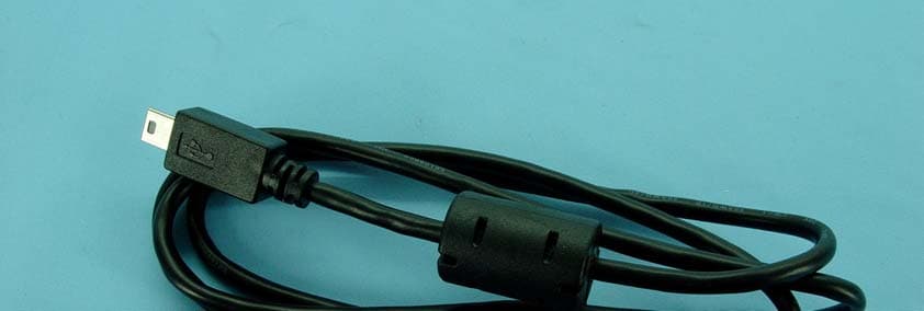
SFMSA205062
Sep 10, 2004Wireless LAN USB Adapter
Equipment Class
DTS - Digital Transmission System