SGP-M618DBM618MINI DB
Shenzhen Delux Industry Co., Ltd.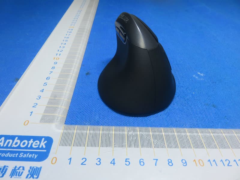
Click to zoom
Application Details
- Equipment Class
- DXX - Part 15 Low Power Communication Device Transmitter
- Date of Grant
- Mar 03, 2020
- Application Purpose
- Original Equipment
- Date of Application
- Mar 03, 2020
- Equipment Note
- M618MINI DB
- Frequency Range
- 2402.00000000 - 2478.00000000
- Country
- China
Documents & Files
Document Text
Text extracted from the exhibit documents filed with the FCC. Open a document above to read the original.
Users Manual
M618mini DB海外标准说明书 李世彬/190131 单色双面印刷 8 ON/OFF button 2.4G/Bluetooth switch button 8 800/1200/1600/2400 1.5V 30mA Dual modes, 2.4GHz+Bluetooth 3.0 2.4G: Pressing the 2.4G/Bluetooth Switch button, the red light lasting for 3 seconds means the current connection mode---2.4G. Connecting the receiver to computer USB port, pressing the left and middle button, the red light will flash when it is programmed successfully. 1.When the Nano receiver is plugged into USB port,your computer will detect the device automatically. 2.Then the mouse can work normally in ON mode. Bluetooth: Pressing the 2.4G/Bluetooth Switch button, the Blue light lasting for 3 seconds means the current connection mode---Bluetooth 3.0. Pressing the button for 2 seconds to enter Bluetooth programming mode, meanwhile, the blue light will keep flashing. When it is programmed successfully the light will be off. If you want to build up the connection with a new device, just press the 2.4G/Bluetooth switch button for 2 seconds and repeat the above steps to connect new devices. left The indicator light will flash once after shifting the DPI to the first grade, will flash twice after shifting the DPI to the second grade, etc. 4 grades in total. Breathing light: Pressing left, middle and right buttons at the same time for 1 second to turn on/off the light. Driver Instruction 1. Installation 2.Setting These functions can be customized as below 3.Macro setting: 4.Other functions: You can also adjust the speed of tracking , double-click and scrolling . After setting the functions please click “Apply”, if you need default functions just click “Restore Defaults” . Basic: Cut, Copy, Paste, etc. 8 functions are available Advanced: Switch window, close window, etc. 6 functions are available . Media:Previous track, next track, stop, etc. 7 functions are available Click “Assign Macro” to enter into Macro settings, click NEW and name the macro, and click “Left click” on any blank space below MACRO SELECT to confirm the name. Then Start Record, after finishing the record, please click “STOP RECORD”, and click “OK” to save the macro. After choosing certain macro, the background of this macro will turn green, you can edit the macro. 1.2. 3.4.5. Download the driver fromor the CD in the package, install the driver. Note: Please make sure this mouse is already connected to computer when setting the functions in the driver. for optional AA Battery -----X1 Model:M618MINI DB FCCSTATEMENT: ThisdevicecomplieswithPart15oftheFCCRules.Operationissubjecttothefollowing twoconditions: (1)Thisdevicemaynotcauseharmfulinterference,and (2)Thisdevicemustacceptanyinterferencereceived,includinginterferencethatmay causeundesiredoperation. Warning:Changesormodificationsnotexpresslyapprovedbythepartyresponsiblefor compliancecouldvoidtheuser'sauthoritytooperatetheequipment. NOTE:ThisequipmenthasbeentestedandfoundtocomplywiththelimitsforaClassB digitaldevice,pursuanttoPart15oftheFCCRules.Theselimitsaredesignedtoprovide reasonableprotectionagainstharmfulinterferenceinaresidentialinstallation.This equipmentgeneratesusesandcanradiateradiofrequencyenergyand,ifnotinstalled andusedinaccordancewiththeinstructions,maycauseharmfulinterferencetoradio communications.However,thereisnoguaranteethatinterferencewillnotoccurina particularinstallation.Ifthisequipmentdoescauseharmfulinterferencetoradioor televisionreception,whichcanbedeterminedbyturningtheequipmentoffandon,the userisencouragedtotrytocorrecttheinterferencebyoneormoreofthefollowing measures: Reorientorrelocatethereceivingantenna. Increasetheseparationbetweentheequipmentandreceiver. Connecttheequipmentintoanoutletonacircuitdifferentfromthattowhichthe receiverisconnected. Consultthedealeroranexperiencedradio/TVtechnicianforhelp.
External Photos
FCC ID: SGP-M618DB
ID Label/Location Info
Label Location On EUT Label Product Name: M618MINI DB Model Number: M618MINI DB FCC ID: SGP-M618DB This device complies with Part 15 of the FCC Rules. Operation is subject to the following two conditions: (1) This device may not cause harmful interference, and (2) This device must accept any interference received, including interference that may cause undesired operation.
Internal Photos
FCC ID: SGP-M618DB ANT
Operational Description
version01 Shenzhen Delux Industry Co., Ltd. Declaration concerning Antenna Specification It is hereby declared that the product Model No.: M618MINI DB FCC ID : SGP-M618DB fulfills the requirement in FCC test relating to the antenna type. The device specified above confirms to the FCC recommendations for internal antenna type(s) described below: Model No. of antenna: N/A Type of antenna: PCB Antenna Gain of the antenna:1dBi Frequency range: BT3.0: 2402~2480MHz & 2.4GHz: 2402~2478MHz The mounting of the antenna is fixed to the radio module and no other antenna should be used. Company name: Shenzhen Delux Industry Co., Ltd. Address: Delux Industrial Park, Lanzhu Street, Shenzhen City, China City:Shenzhen ZIP / Postal code: Country: China Place: Shenzhen Date: 2020-02-29 Signature:
RF Exposure Info
RF EXPOSURE EVALUATION FCC ID: SGP-M618DB According to FCC 1.1310: The criteria listed in the following table shall be used to evaluate the environment impact of human exposure to radio frequency(RF) Radiation as specified in §1.1307(b): Routine SAR evaluation refers to that specifically required by §2.1093, using measurements or computer simulation. When routine SAR evaluation is not required, portable transmitters with output power greater than the applicable low threshold require SAR evaluation to qualify for TCB approval. For BT Channel (MHz) Maximum output power (dBm) Tune up tolerance (dBm) Max Tune Up Power (dBm) Distance (mm) Calculation results Limit Operating Mode 2402 -7.466 -7.466±1 -6.466 5 0.070 3 BDR 2441 -7.580 -7.580±1 -6.580 5 0.069 3 2480 -8.072 -8.072±1 -7.072 5 0.062 3 For 2.4G Channel (MHz) Max power (dBuV/m) Max output power (dBm) Tune up tolerance (dBm) Max Tune Up Power (dBm) Max Tune Up Power (mW/cm 2 ) Distance (mm) Calcula tion results Limit 2402 92.27 -2.9875 -2.9875±1 -1.9875 0.64 5 0.197 3 2441 93.97 -1.2875 -1.2875±1 -0.2875 0.94 5 0.293 3 2478 92.58 -2.6775 -2.6775±1 -1.6775 0.68 5 0.215 3 E=EIRP-20Log D+104.8 Where: E= electric field strength in dBuV/m EIRP= equivalent isotropic radiated power in dBm D= specified measurement distance in meters EIRP= E-104.8+20logD= 92.27 -104.8+20log3= -2.9875 dbm Note 1: Calculation Value = [(max. power of channel, included tune-up tolerance, mW)/(min.test separation distance, mm)] ·[√f(GHz)]. Fox example:0.64/5*√2.402=0.197≤3.0 Test Results: PASS.
Test Report
Shenzhen Anbotek Compliance Laboratory Limited FCC ID: SGP-M618DB Page 1 of 29 Report No.: SZAWW181219002-02 Shenzhen Anbotek Compliance Laboratory Limited Tel:(86)755-26066440 Fax:(86)755-26014772 www.anbotek.com Code:AB-RF-05-a FCC TEST REPORT For Shenzhen Delux Industry Co., Ltd. M618MINI DB Model No.: M618MINI DB Prepared For: Shenzhen Delux Industry Co., Ltd. Address: Delux Industrial Park, Lanzhu Street New Pingshan District, Shenzhen, China Prepared By: Shenzhen Anbotek Compliance Laboratory Limited Address: 1/F, Building D, Sogood Science and Technology Park, Sanwei community, Hangcheng Street, Bao'an District, Shenzhen, Guangdong, China.518102 Tel: (86) 755-26066440 Fax: (86) 755-26014772 Report Number: SZAWW181219002 -02 Date of Receipt: Dec. 19, 2018 Date of Test: Dec. 19, 2018~Feb. 23, 2019 Date of Report: Mar. 03, 2020 Shenzhen Anbotek Compliance Laboratory Limited FCC ID: SGP-M618DB Page 2 of 29 Report No.: SZAWW181219002-02 Shenzhen Anbotek Compliance Laboratory Limited Tel:(86)755-26066440 Fax:(86)755-26014772 www.anbotek.com Code:AB-RF-05-a Contents 1. General Information .................................................................................................................................................. 4 1.1. Client Information ......................................................................................................................................... 4 1.2. Description of Device (EUT) ........................................................................................................................ 4 1.3. Auxiliary Equipment Used During Test ........................................................................................................ 4 1.4. Description of Test Modes ............................................................................................................................. 5 1.5. List of Channels ............................................................................................................................................. 5 1.6. Description of Test Setup ............................................................................................................................... 6 1.7. Test Equipment List ....................................................................................................................................... 7 1.8. Description of Test Facility ........................................................................................................................... 8 2. Summary of Test Results .......................................................................................................................................... 9 3. Conducted Emission Test ........................................................................................................................................ 10 3.1. Test Standard and Limit ............................................................................................................................... 10 3.2. Test Setup ..................................................................................................................................................... 10 3.3. Test Procedure .............................................................................................................................................. 10 3.4. Test Data ...................................................................................................................................................... 10 4. Radiated Emission and Band Edge ......................................................................................................................... 11 4.1. Test Standard and Limit ............................................................................................................................... 11 4.2. Test Setup ..................................................................................................................................................... 11 4.3. Test Procedure .............................................................................................................................................. 13 4.4. Test Data ...................................................................................................................................................... 13 5. 20dB Bandwidth Test .............................................................................................................................................. 23 5.1. Test Standard and Limit ............................................................................................................................... 23 5.2. Test Setup ..................................................................................................................................................... 23 5.3. Test Procedure .............................................................................................................................................. 23 5.4. Test Data ...................................................................................................................................................... 23 6. Antenna Requirement ............................................................................................................................................. 26 6.1. Test Standard and Requirement ................................................................................................................... 26 6.2. Antenna Connected Construction ................................................................................................................ 26 APPENDIX I -- TEST SETUP PHOTOGRAPH ....................................................................................................... 27 APPENDIX II -- EXTERNAL PHOTOGRAPH ....................................................................................................... 28 APPENDIX III -- INTERNAL PHOTOGRAPH ................…
Text truncated - open the document above for the full version.
Test Setup Photos
FCC ID: SGP-M618DB Photo of Radiation Emission Test
Contact Information
Applicant
Feiyun Zhang(Manager Assistant)
Test Firm
Shenzhen Anbotek Compliance Laboratory LimitedJeff Zhu
Technical Specifications
| # | Rule Parts | Frequency Range | Power Output |
|---|---|---|---|
| 1 | 15C | 2.40 GHz - 2.48 GHz | 750.00 µW |
Other Applications from Shenzhen Delux Industry Co., Ltd.
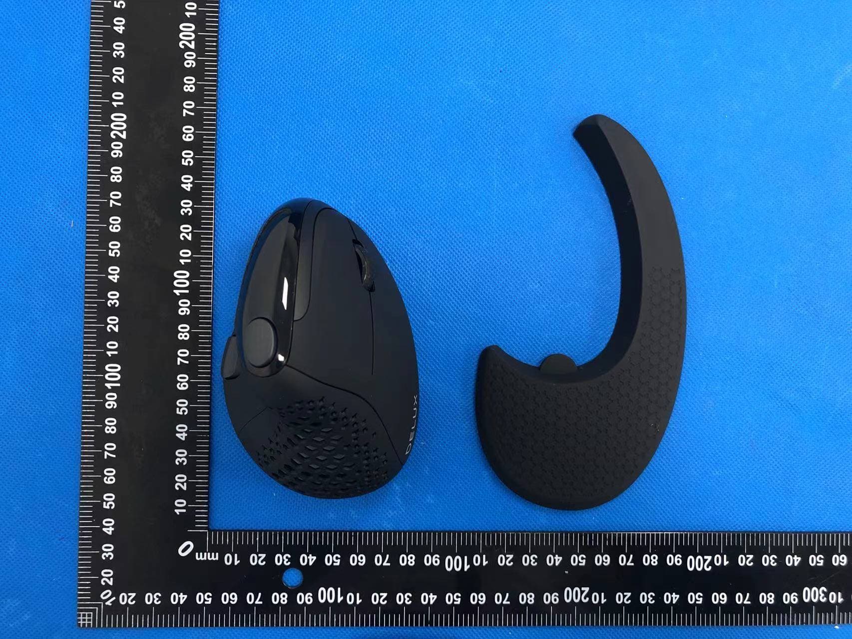
SGP-M618XSD
Apr 13, 2022Wireless mouse
Equipment Class
DTS - Digital Transmission System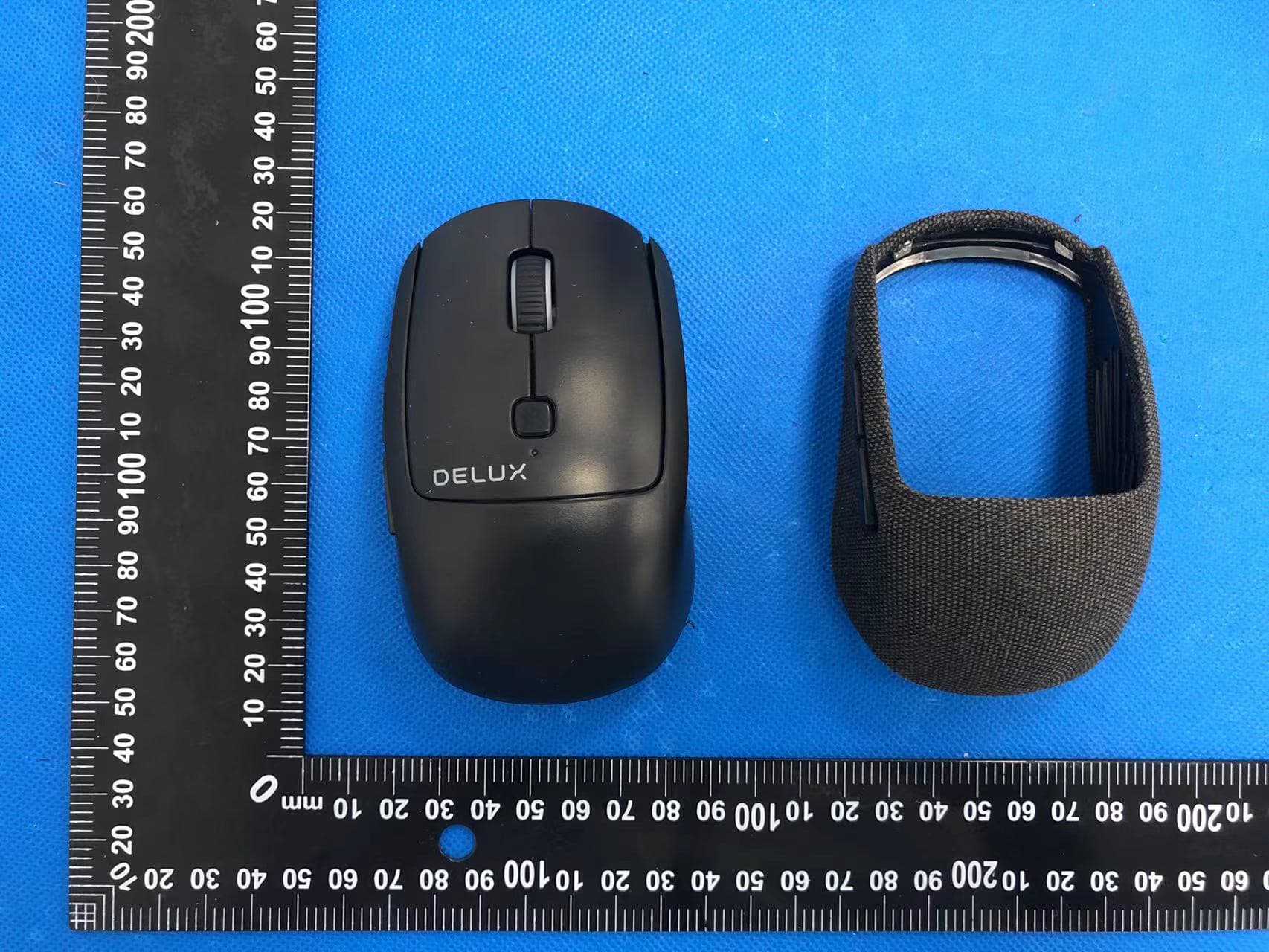
SGP-M520DB
Apr 13, 2022Wireless mouse
Equipment Class
DTS - Digital Transmission System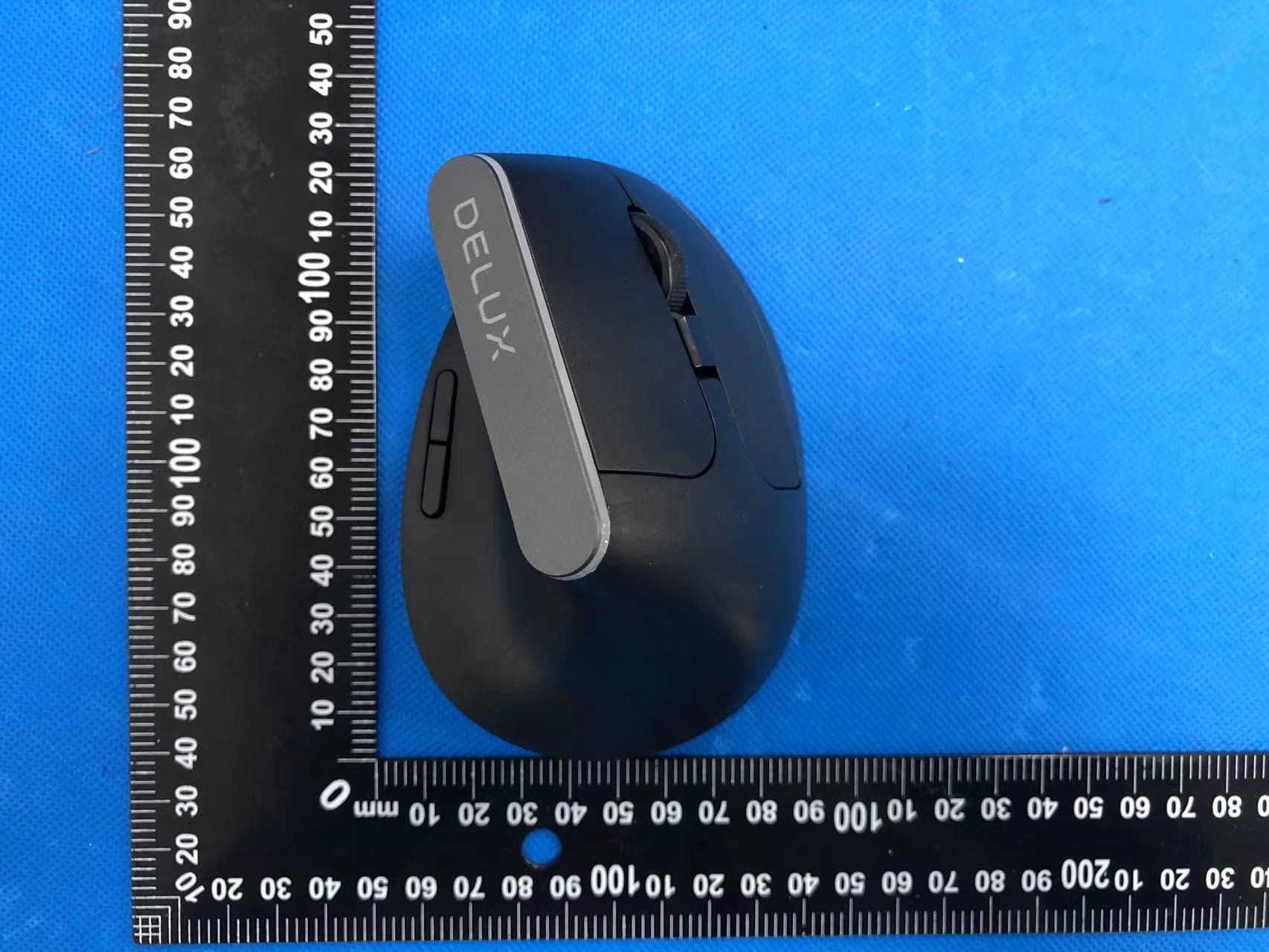
SGP-M618C
Apr 11, 2022Wireless mouse
Equipment Class
DTS - Digital Transmission System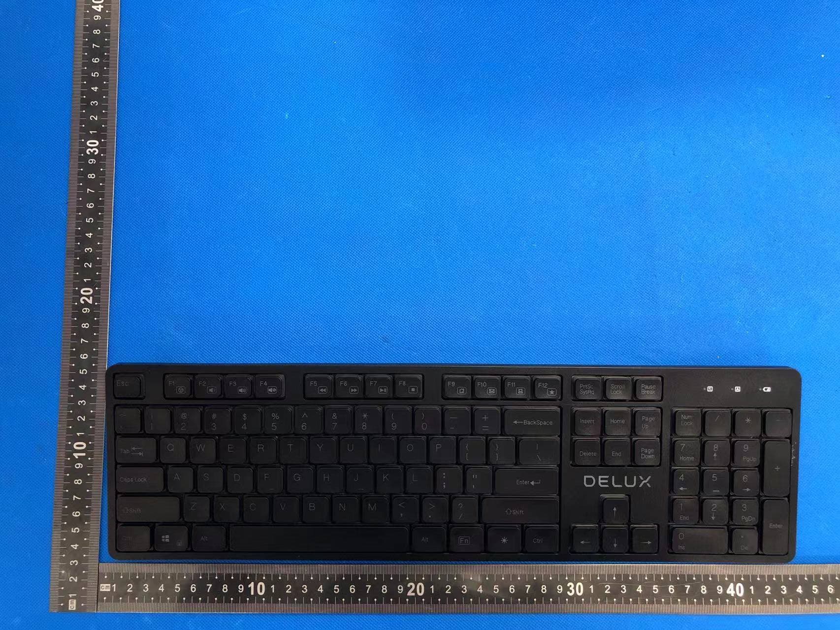
SGP-SK800
Apr 11, 2022Wireless keyboard
Equipment Class
DTS - Digital Transmission System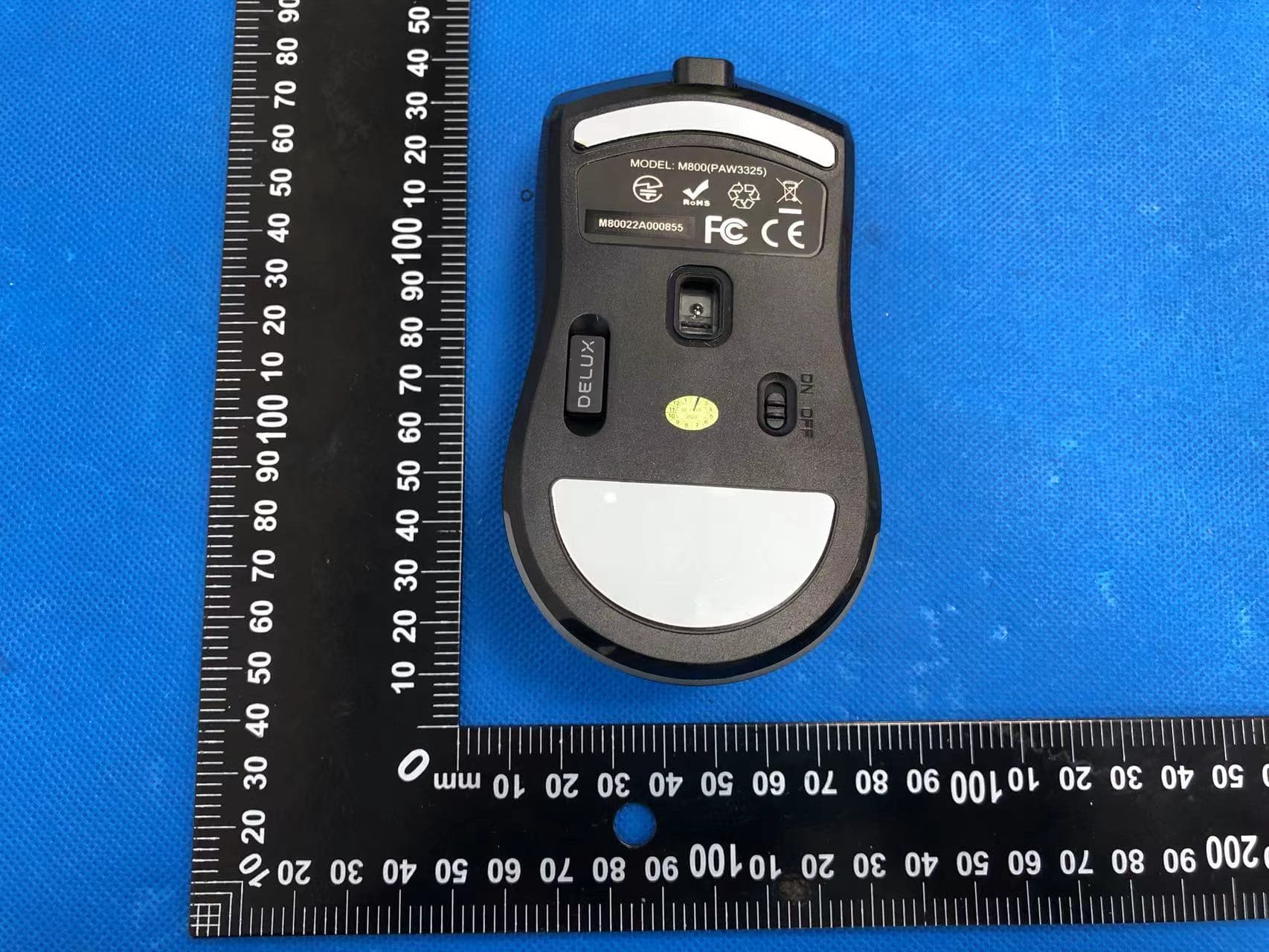
SGP-M800DB
Apr 11, 2022Wireless mouse
Equipment Class
DTS - Digital Transmission System