SGRB35100001Android TV Box
Shenzhen Tena Electronic CO.,Ltd.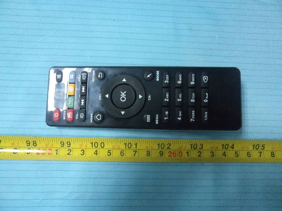
Click to zoom
Application Details
- Equipment Class
- DTS - Digital Transmission System
- Date of Grant
- Nov 24, 2013
- Application Purpose
- Original Equipment
- Date of Application
- Nov 24, 2013
- Equipment Note
- Android TV Box
- Frequency Range
- 2422.00000000 - 2452.00000000
- Country
- China
Documents & Files
Document Text
Text extracted from the exhibit documents filed with the FCC. Open a document above to read the original.
Users Manual
Table of Contents 1.Package contents 2.Buttons and Ports 3.The remote control 4.Get started 4.1 Turn the unit on 4.2 Home interface 4.3 Language and Input 4.4 Connect to internet 4.5 Install/uninstall APK 4.6 Operate MP as remote control 4.7 DLNA、Miracast intruduction 5.Trouble-shooting .................................11 .................................11 ...............................12 ......................................15 ..................................15 ..................................16 ..............................16 ..............................17 ..............................18 ........................19 .......................20 .................................21 1 Thank you for purchasing this product, the operational guidelines below contains important information about safe and proper use of this device to avoid accidents, so please read the instructions carefully before use. Store the unit away from high temperature, extreme moisture or dust . Avoid strong impact or any collision with the product. Do not interrupt the power while in the process of upgrading or uploading/downloading the firmware, to avoid data loss or program error. This product is a high precision electronic product, do not disassemble or clean it with alcohol, thinner and benzene solution. The maker reserves the right to upgrade the product, product specification and design is subject to change without prior notice. Disclaimer: The maker assumes responsibility for warranty service of the product itself and assume no responsibility for the data loss. The unit is not water-proof. Pictures contained in this manual are for reference only. ! ! ! ! ! ! ! ! ! Opening Note 2 1.Package Contents Number Items Quantity 1 2 3 4 5 6 HDMI CABLE POWER ADAPTOR AV CABLE INFRARED REMOTE CONTROLLER USER MAUNAL 1 PCS Note: The accessories may be slightly different from the list above due to different models specifications and subject to the product purchased. 2. BUTTONS AND PORTS (Note:The ports and its layout may change for some models, please refer to silkscreen designators on the unit) 1 PCS 1 PCS 1 PCS 1 PCS 1 PCS Items Description/Function DC+5V Connect to power supply, please use or iginal power adapter Stream audio and video signal to TV or PC display with an AV cable(1 to 3) Connect to a PC via an adapter Stream audio and high resolution video to TV or PC display AV OUT HDMI OTG 3 Android TV Box SPDIF fibre-optical output for audio Standard RJ45, connect to internet through network cable Connect to external memory card Reinstall system firmware LAN TF card slot Power Reset 3. The remote control This device comes with a remote control,of which most functions can be operated with navigation keys. For some APK, switch the mouse mode by pressing the mouse key before operation. USB Connect to 2.4GHZ USB device Turn on or off the unit, or let it standby Connect to 3.5mm microphone Connect to external SD Card MIC SD Icon Key Function Power on/off/standby Power Silent Mute the sound Multimedia Hotkey for music player TV Hotkey for video player Browser Hotkey for internet browser TV 4 Mouse FF-/CH UP Turn to last programme while playing FF+/CH DOWN Turn to next programme while playing Home Page Back to home page RETURN Return to last page /operation MOUSE APK Enter APK listing Remote navigation mode by default, press mouse key for 1 second above to enter mouse mode, and press it for another 1 second above to return to remote navigation. TV CH+ HOMERETURN MEDIA TV APP OK VOL-VOL+ CH- MENUMOUSE 1.;/@2ABC3DEF 4GHI 5JKL6MNO 7PQRS 8TUV9WXYZ 1/A/a 0 WEB 5 CH+ Turn to last channel:Turn to last programme while pressing this key during playing CH- Turn to next channel:Turn to next programme while pressing this key during playing Menu Options CH+ CH- Navigation Upward、 downward、left、 right navigation Confirm In mouse mode, it functions as the left key, while in remote navigation, it serves as “enter” key Volume up Decrease the sound Increase the sound Volume down OK 6 0~9/ABC Numbers/Letters /Symbols Input method Capital/small letter Backspace Move backwards and delete the character 1/A/a/中 9WXYZ 1.;/@ 4. Get started 4.1 Connection and turn on the unit The steps below is for connection through an HDMI cable, if an AV cable is used, please connect it to AV(yellow、R(red)、 L(white) ports respectively on TV. 1.Connect one end of the supplied HDMI cable to the Smart TV Box, the other end to an HDMI port on TV or other display device, and connect the AC power adapter (5V/2A)to the unit and the other end to the power socket. 2.Turn on the unit by pressing the power key until the LED indicator lights up. 3.Use TV remote control(the signal source key) to select right signal path for the HDMI port connected. There are normally several HDMI ports on a TV, and the connection can be enabled only when the right signal path is selected. If an AV cable is used, please select AV port instead. 7 Note:The LED indicator lights up constantly after the device is switched on or in operation. In standby state, short press once the power key on the device or on the remote control, the device is switched on and the LED indicator lights up. 4.2 Home interface Plug the device into power socket, long press power key until LED indicator lights up, and after 3-5 seconds, the TV display shows starting up. After a while, home interface pop up, and click on APK listing to show icons of all installed APK on the device. 4.3 Lauguage and input method Setting→Language and input, select different languages here; User can install their own input software and check the option of this input method. While inputting, you can select input method by clicking on input area, and then clicking on the icon of keyboard on the bottom-right corner to show a list of all input methods available for selection. Language English 8 4.4 Connect to internet Wireless connection Setting,→Wi-Fi, click on the desired wifi hot spot, and input password of the wireless router for connectio…
Text truncated - open the document above for the full version.
External Photos
EXHIBIT B - EUT EXTERNAL PHOTOGRAPHS EUT – Top View EUT – Bottom View EUT – Front View EUT – Rear View EUT – Left Side View EUT – Right Side View EUT – Remote Control View EUT – AV Cable View EUT – HDMI Cable View EUT – Adapter View EUT – Adapter Label View
ID Label/Location Info
EXHIBIT A - FCC ID LABELING AND LOCATION FCC ID Label FCC ID Label Location The label shown shall be permanently affixed at a conspicuous location on the device and be readily visible to the user at the time purchase (Labeling requirements per 2.925) Label here
Internal Photos
EXHIBIT C - EUT INTERNAL PHOTOGRAPHS EUT – Cover off View 1 EUT – Cover off View 2 EUT – Main Board Top View EUT – Main Board Top Shielding off View EUT – Main Board Bottom View EUT – Main Board Bottom Shielding off View
RF Exposure Info
Bay Area Compliance Laboratories Corp. (Shenzhen) Report No.: RSZ131014002-00B FCC Part 15.247 Page 9 of 64 FCC §15.247 (i) & §1.1307 (b) (1) & §2.1091- MAXIMUM PERMISSIBLE EXPOSURE (MPE) Applicable Standard According to subpart 15.247 (i) and subpart 1.1307 (b)(1), 2.1091 systems operating under the provisions of this section shall be operated in a manner that ensures the public is not exposed to RF energy level in excess of the communication guidelines. Limits for General Population/Uncontrolled Exposure Limits for General Population/Uncontrolled Exposure Frequency Range (MHz) Electric Field Strength (V/m) Magnetic Field Strength (A/m) Power Density (mW/cm 2 ) Averaging Time (Minutes) 0.3-1.34 614 1.63 *(100) 30 1.34-30 824/f 2.19/f *(180/f 2 ) 30 30-300 27.5 0.073 0.2 30 300-1500 / / f/1500 30 1500-100,000 / / 1.0 30 f = frequency in MHz * = Plane-wave equivalent power density Result Calculated Formulary: Predication of MPE limit at a given distance S = 2 4R PG S = power density (in appropriate units, e.g. mW/cm 2 ) P = power input to the antenna (in appropriate units, e.g., mW). G = power gain of the antenna in the direction of interest relative to an isotropic radiator, the power gain factor, is normally numeric gain. R = distance to the center of radiation of the antenna (appropriate units, e.g., cm) Antenna Gain Conducted Power Frequency (MHz) (dBi) (numeric) (dBm) (mW) Evaluation Distance (cm) Power Density (mW/cm 2 ) MPE Limit (mW/cm 2 ) 2462 2.5 1.78 17.66 58.34 20 0.021 1.0 FCC Radiation Exposure Statement: To comply with FCC RF exposure requirements, a minimum separation distance of 20 cm is required between the antenna and all public persons. Result: Compliance
Test Report
Note: This test report is prepared for the customer shown above and for the equipment described herein. It may not be duplicated or used in part without prior written consent from Bay Area Compliance Laboratories Corp. FCC PART 15.247 MEASUREMENT AND TEST REPORT For Shenzhen Tena Electronic Co., Ltd. 9 Floor IER Building, South Area, Hi-Tech Industrial Park, Shenzhen, Guangdong, China Report Type: Original Report Product Type: Android TV Box Test Engineer: Sula Huang Report Number: RSZ131014002-00B Report Date: 2013-11-13 Reviewed By: Alvin Huang RF Leader Prepared By: Bay Area Compliance Laboratories Corp. (Shenzhen) 6/F, the 3rd Phase of WanLi Industrial Building ShiHua Road, FuTian Free Trade Zone Shenzhen, Guangdong, China Tel: +86-755-33320018 Fax: +86-755-33320008 www.baclcorp.com.cn FCC ID: SGRB35100001 Bay Area Compliance Laboratories Corp. (Shenzhen) Report No.: RSZ131014002-00B FCC Part 15.247 Page 2 of 64 TABLE OF CONTENTS GENERAL INFORMATION.......................................................................................................................................4 PRODUCT DESCRIPTION FOR EQUIPMENT UNDER TEST (EUT) .....................................................................................4 OBJECTIVE...................................................................................................................................................................4 RELATED SUBMITTAL(S)/GRANT(S).............................................................................................................................4 TEST METHODOLOGY..................................................................................................................................................4 TEST FACILITY.............................................................................................................................................................5 SYSTEM TEST CONFIGURATION ..........................................................................................................................6 DESCRIPTION OF TEST CONFIGURATION......................................................................................................................6 EUT EXERCISE SOFTWARE..........................................................................................................................................6 EQUIPMENT MODIFICATIONS.......................................................................................................................................7 SUPPORT EQUIPMENT LIST AND DETAILS....................................................................................................................7 EXTERNAL I/O CABLING LIST AND DETAILS................................................................................................................7 BLOCK DIAGRAM OF TEST SETUP................................................................................................................................7 SUMMARY OF TEST RESULTS...............................................................................................................................8 FCC §15.247 (i) & §1.1307 (b) (1) & §2.1091- MAXIMUM PERMISSIBLE EXPOSURE (MPE) ............................9 APPLICABLE STANDARD..............................................................................................................................................9 RESULT........................................................................................................................................................................9 FCC §15.203 - ANTENNA REQUIREMENT...........................................................................................................10 APPLICABLE STANDARD............................................................................................................................................10 ANTENNA CONNECTOR CONSTRUCTION....................................................................................................................10 FCC §15.207 (a) - CONDUCTED EMISSIONS .......................................................................................................11 APPLICABLE STANDARD............................................................................................................................................11 MEASUREMENT UNCERTAINTY..................................................................................................................................11 EUT SETUP................................................................................................................................................................11 EMI TEST RECEIVER SETUP.......................................................................................................................................12 TEST EQUIPMENT LIST AND DETAILS.........................................................................................................................12 TEST PROCEDURE......................................................................................................................................................12 CORRECTED FACTOR & MARGIN CALCULATION.......................................................................................................13 TEST RESULTS SUMMARY..........................................................................................................................................13 TEST DATA................................................................................................................................................................13 FCC §15.209, §15.205 & §15.247(d) - SPURIOUS EMISSIONS.............................................................................16 APPLICABLE STANDARD............................................................................................................................................16 MEASUREMENT UNCERTAINTY.........................................…
Text truncated - open the document above for the full version.
Test Setup Photos
EXHIBIT D - TEST SETUP PHOTOGRAPHS Conducted Emissions –Front View Conducted Emissions-Side View Radiated Emissions – Front View (Below 1GHz) Radiated Emissions – Rear View (Below 1GHz) Radiated Emissions – Front View (Above 1GHz) Radiated Emissions – Rear View (Above 1GHz)
Contact Information
Applicant
Jerome Pan
Test Firm
Bay Area Compliance Laboratory Corp. (Shenzhen)John Chan
Technical Specifications
| # | Rule Parts | Frequency Range | Power Output |
|---|---|---|---|
| 2 | 15C | 2.42 GHz - 2.45 GHz | 27.00 mW |
Other Applications from Shenzhen Tena Electronic CO.,Ltd.
SGRS3130001
Nov 24, 2013MULTI-SCREEN INTERACTIVE DEVICE
Equipment Class
DTS - Digital Transmission System
SGRS311A0001
Nov 05, 2013MULTI-SCREEN INTERACTIVE DEVICE
Equipment Class
DTS - Digital Transmission System
SGRDBF000002
May 12, 2013Android Mini PC Box
Equipment Class
DTS - Digital Transmission System