SJ8-45242TTOOL BOX REMOTE
RDI Technology (Shenzhen) Co., Ltd.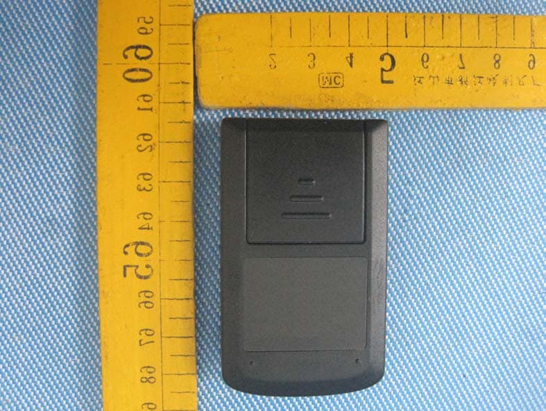
Click to zoom
Application Details
- Equipment Class
- DSC - Part 15 Security/Remote Control Transmitter
- Date of Grant
- Jan 07, 2013
- Application Purpose
- Original Equipment
- Date of Application
- Jan 07, 2013
- Equipment Note
- TOOL BOX REMOTE
- Frequency Range
- 433.92000000 - 433.92000000
- Country
- China
Documents & Files
Document Text
Text extracted from the exhibit documents filed with the FCC. Open a document above to read the original.
Users Manual
Do not use in wet locations Personal Security Indoor/Outdoor Wireless Alarm with Remote User Manual A r m D i s a r m Table of Contents Introduction 3 Installing Batteries 6 Low Battery Indicator Light 7 Linking the Alarm 8 Installation 11 Arming the Alarm 14 Disarming the Alarm 15 Care and Maintenance 16 Battery warnings 17 FCC Warning 17 Wireless Alarm with Remote Before installing or operating the Indoor/ Outdoor Wireless Alarm with Remote, please read these instructions carefully and save this manual for future reference. Important Safeguards Pre Cautions 1. Do not attempt to disassemble the Keychain Remote or the Alarm unless described in the user’s manual. There are no user serviceable parts. 2. Handle with Care – Avoid striking or shaking. Improper use or storage could damage the Keychain Remote or the Alarm. Modifying or tampering with either device or the internal components can cause a malfunction and void the warranty. 3. If you feel the Keychain Remote or any part of the Alarm system is not operating correctly or as described, please contact Technical Support for assistance (1-800-654-8483), - For use indoor or outdoors. - Works in weather down to 0° F. 4 Introduction The Indoor/Outdoor Wireless Alarm with Keychain Remote allows you to add protection or monitor areas in and around your home. Use on gates, sheds, garages, cabinets, tool boxes and personal truck boxes. Please note below: Remote: 1. The Keychain Remote will transmit up to 30ft from the Alarm. However, like all wireless devices, this distance is subject to conditions of the Alarm’s location; the number of walls and appliances between the Keychain Remote and the Alarm can reduce the signal transmission distance. 2. After either button is pressed, the remote will transmit for approx two seconds. There is a two second delay before the remote can transmit a new command (pressing another button). Magnet Content: When the magnet and wired contact are separated (door or lid opened), the red indicator on the front of the Alarm will begin flashing indicating the Alarm has been activated. The Alarm’s siren will begin sounding within 1 second or 5 seconds (depending on the delay entry time setting). The Alarm will continue to sound until disarmed by a linked remote. 5 A r m D i s a r m 6 Adjustable Wired Contact Cable Battery Compartment Battery Compartment Screws (2) Learn Button 7 Installing Batteries The battery compartment is located on the back of the Alarm and Keychain Remote Alarm Insert 3-AAA batteries (not included). Please note the polarity diagram inside the battery compartment. Keychain Remote Insert 1-2 3A battery (included). Please note the polarity diagram inside the battery compartment. 1. Replace the cover by first inserting TABS at base and secure screws. 8 Low Battery Indicator Light The Indoor/Outdoor Wireless Alarm has a low battery indicator light. When the batteries need to be replaced, the indicator will flash slowly. Note: Average battery life for typical usage is up to one year. Linking the remote to the Alarm Make sure you have installed the batteries in the Alarm and Keychain Remote. Locate the learn button on the inside of the battery compartment . 2. Press the learn button in the battery compartment as seen above. The Indicator light will start to flash on the Keychain Remote. 3. Now press the Arm button on the Keychain remote. The Alarm will sound a single short tone, and the light will stop flashing to confirm the remote has been linked to the Alarm. A r m 9 Note: additional remotes can be added to the system by following the same programing procedure. 4. Replace cover to the battery compartment by first inserting tabs of battery compartment cover and secure screws. Delayed Entry Time The Alarm defaults delay is one second. This is the amount of time the Alarm will delay once triggered. (i.e. door opened when Alarm is set). There is an alternate delay setting of 5 seconds. Changing the delayed entry time length 1. The Alarm must not be armed. 2. Press and hold the Disarm button on the Keychain Remote approx. three seconds and you will hear a short beep. Release the Disarm button. This indicates you have now changed the delay entry time. Follow the same steps to change back to the one second setting. 10 Installing the Alarm 1. The unit is designed to be used indoor or outdoors. It can be mounted in toolboxes, inside personal truck boxes or on gates, sheds, and doors etc. 2. Selecting the best location will depend on the intended use. Below are some suggested mounting options. Regardless of location, the gap between the wired Contact and the Magnet must not be greater than 3/4” in the closed position. Double sided mounting tape Anchored screws mounting The mounting surface will determine whether to use the double-sided tape or mounting screws. DO NOT USE screws if mounting surface is less than two inches thick. 11 Tool boxes or Personal truck boxes Inside of truck boxes or toolboxes - use the two sided installation tape included 12 Inside of doors - use the two sided installation tape included or if the mounting surface is over two inches thick Use the anchors and screws provided. Cabinets, Slidiing Doors and Doors 13 The Alarm is weather resistant so it can be mounted outside. The preferred location is to mount the Alarm and wired Contact on the gate and the Magnet to the fixed post or wall. When mounting to a wood or porous surface, you can use the extra mounting plates. These can be securely mounted to the surface, and the wired contact and magnet can be attached using the double sided tape. Inside of gates - use the two sided installation tape included or if wood is over two inches thick use screws included. Gates 14 Mounting plate will snap to lock in place. Note: To remove the Alarm, push locking TAB, lide the Alarm upwards off the mounting plate. Use the provided double- sided stick tape, to mount to most surfaces. For porous surfaces use optional mounting plates. Line up arrows up to 3/…
Text truncated - open the document above for the full version.
Cover Letter(s)
RDI Technology (Shenzhen) Co., Ltd. Date: Dec. 06, 2012 Federal Communications Commission Authorization and Evaluation Division Confidentiality Request regarding application for certification of FCC ID: SJ8-45242T Pursuant to Sections 0.457 and 0.459 of the Commission’s Rules, we hereby request confidential treatment of information accompanying this application as outlined below: Exhibit Type File Name Schematics Block Diagram Operational Description SCH.pdf BlockDiagram.pdf CircuitDescription.pdf The above materials contain trade secrets and proprietary information not customarily released to the public. The public disclosure of these materials may be harmful to the applicant and provide unjustified benefits to its competitors. The applicant understands that pursuant to Section 0.457 of the Rules, disclosure of this application and all accompanying documentation will not be made before the date of the Grant for this application. Sincerely, RDI Technology (Shenzhen) Co., Ltd . ................................................... Signature Tony Zhou/ Engineering Manager ................................................... Typed name and Title
Cover Letter(s)
RDI Technology (Shenzhen) Co., Ltd. FCC ID: SJ8-45242T POWER OF ATTORNEY Date: Dec.06,2012 Federal Communications Commission Authorization and Evaluation Division 7435 Oakland Mills Road Columbia, MD 21046 To Whom It May Concern: We, the undersigned, hereby authorize Waltek Services (ShenZhen) Co., Ltd. (Philo Zhong) on our behalf, to apply to the Federal Communications Commission on our equipment. Any and all acts carried out by Waltek Services (ShenZhen) Co., Ltd. (Philo Zhong) on our behalf shall have the same effect as acts of our own. This authorization expires on Dec.06,2013. This is to advise that we are in full compliance with the Anti-Drug Abuse Act. We, RDI Technology (Shenzhen) Co., Ltd. are not subject to a denial of federal benefits pursuant to Section 5301 of the Anti-Drug Act of 1988, 21 USC853a, and no party to the application is subject to a denial of federal benefits pursuant to that section. Sincerely, RDI Technology (Shenzhen) Co., Ltd. ................................................................................. Signature Tony Zhou/ Engineering Manager ................................................................................. Typed name and Title
External Photos
ReferenceNo.:WT12127960-F-S-FPage 21 of 26 WaltekServices(Shenzhen)Co.,Ltd. http://www.waltek.com.cn 12 12 12 12 Photographs Photographs Photographs Photographs- - - -Constructional Constructional Constructional ConstructionalDetails Details Details Details 12.1 12.1 12.1 12.1EUT EUT EUT EUT– – – –Appearance Appearance Appearance AppearanceView View View View ReferenceNo.:WT12127960-F-S-FPage 22 of 26 WaltekServices(Shenzhen)Co.,Ltd. http://www.waltek.com.cn ReferenceNo.:WT12127960-F-S-FPage 23 of 26 WaltekServices(Shenzhen)Co.,Ltd. http://www.waltek.com.cn
ID Label/Location Info
Reference No.: WT12127960-F-S-F Page 25 of 25 Waltek Services (Shenzhen) Co.,Ltd. http://www.waltek.com.cn 13 FCC Label FCC ID: SJ8-45242T This device complies with Part 15 of the FCC Rules. Operation is subject to the following two conditions: (1) this device may not cause interference, and (2) this device must accept any interference, including interference that may cause undesired operation of the device. The Label must not be a stick-on paper. The Label on these products must be permanently affixed to the product and readily visible at the time of purchase and must last the expected lifetime of the equipment not be readily detachable. =End of report=
ID Label/Location Info
RDITechnology(Shenzhen)Co.,Ltd.FCCID:SJ8-45242T FCC FCC FCC FCCLabel Label Label Label TheLabelmustnotbeastick-onpaper.TheLabelontheseproductsmustbepermanentlyaffixed totheproductandreadilyvisibleatthetimeofpurchaseandmustlasttheexpectedlifetimeofthe equipmentnotbereadilydetachable. ProposedLabelLocationonEUT EUTBackView/proposedFCCLabelLocation FCCID:SJ8-45242T Thisdevicecomplieswith Part15oftheFCC Rules.Operationissubject tothefollowingtwo conditions:(1)thisdevice maynotcauseharmful interference,and(2)this devicemustacceptany interference received,including interferencethatmay causeundesiredoperation.
Internal Photos
ReferenceNo.:WT12127960-F-S-FPage 24 of 26 WaltekServices(Shenzhen)Co.,Ltd. http://www.waltek.com.cn 12.2 12.2 12.2 12.2EUT EUT EUT EUT– – – –Open Open Open OpenView View View View 12.3 12.3 12.3 12.3EUT EUT EUT EUT– – – –PCB PCB PCB PCBView View View View ReferenceNo.:WT12127960-F-S-FPage 25 of 26 WaltekServices(Shenzhen)Co.,Ltd. http://www.waltek.com.cn
Test Report
Reference No.: WT12127960-F-S-F Page 1 of 25 FCC TEST REPORT Waltek Services (Shenzhen) Co.,Ltd. http://www.waltek.com.cn FCC ID : SJ8-45242T Applicant : RDI Technology (Shenzhen) Co., Ltd. Address : Building C1 Xintang Industrial Park, East Baishixia, Fuyong, Baoan, Shenzhen, PRC Manufacturer : RDI Technology (Shenzhen) Co., Ltd. Address : Building C1 Xintang Industrial Park, East Baishixia, Fuyong, Baoan, Shenzhen, PRC Equipment Under Test (EUT) : Product Name : Tool box remote Model No. : 45242T Rules : FCC CFR47 Part 15 Section 15.231:2010 Date of Test : Dec.04~06, 2012 Date of Issue : Dec. 07, 2012 Test Result : PASS* Remark: * The sample described above has been tested to be in compliance with the requirements of the rules listed above. The results shown in this test report refer only to the sample(s) tested, this test report cannot be reproduced, except in full, without prior written permission of the company. The report would be invalid without specific stamp of test institute and the signatures of compiler and approver. PERPARED BY: Waltek Services (Shenzhen) Co., Ltd. 1/F, Fukangtai Building, West of Baima Road., Songgang Street, Bao’an District, Shenzhen, China Tel: +86-755-83551033 Fax: +86-755-83552400 Compiled by: Approved by: Zero Zhou / Project Engineer Philo Zhong / Manager Reference No.: WT12127960-F-S-F Page 2 of 25 Waltek Services (Shenzhen) Co.,Ltd. http://www.waltek.com.cn 2 Content Page 1 COVER PAGE ...........................................................................................................................................1 2 CONTENT ............................................................................................................................................................... 2 3 TEST SUMMARY ................................................................................................................................................... 3 4 GENERAL INFORMATION .................................................................................................................................. 4 4.1 GENERAL DESCRIPTION OF E.U.T. ................................................................................................................ 4 4.2 DETAILS OF E.U.T. .......................................................................................................................................... 4 4.3 TEST FACILITY ................................................................................................................................................. 4 4.4 TEST LOCATION ............................................................................................................................................... 4 4.5 GENERAL CONDITION ...................................................................................................................................... 4 4.5.1 Environmental condition of test site ....................................................................................................... 5 4.5.2 Test Mode .................................................................................................................................................. 5 5 EQUIPMENT USED DURING TEST ................................................................................................................... 6 5.1 EQUIPMENTS LIST ........................................................................................................................................... 6 5.2 MEASUREMENT UNCERTAINTY ....................................................................................................................... 6 5.3 TEST EQUIPMENT CALIBRATION ..................................................................................................................... 6 6 CONDUCTED EMISSION TEST ......................................................................................................................... 7 7 RADIATION EMISSION TEST ............................................................................................................................. 8 7.1 TEST PROCEDURE........................................................................................................................................... 8 7.2 RADIATED TEST SETUP ................................................................................................................................... 8 7.3 SPECTRUM ANALYZER SETUP ........................................................................................................................ 9 7.4 CORRECTED AMPLITUDE & MARGIN CALCULATION ....................................................................................... 9 7.5 LIMIT ................................................................................................................................................................ 9 7.6 TEST RESULT ................................................................................................................................................ 11 8 ACTIVATION TIME .............................................................................................................................................. 14 8.1 TEST PROCEDURE......................................................................................................................................... 14 8.2 TEST RESULT ................................................................................................................................................ 14 9 20 DB BANDWIDTH ............................................................................................................................................ 17 9.1 TEST PROCEDURE......................................................................................................................................... 17 9.2 LIMIT .....................................................................................................................................…
Text truncated - open the document above for the full version.
Test Setup Photos
Reference No.: WT12127960-F-S-F Page 19 of 25 Waltek Services (Shenzhen) Co.,Ltd. http://www.waltek.com.cn 11 Photographs of Testing 11.1 Photographs –Radiated Emission Test Setup TX From 30MHz to 1GHz TX Above 1 GHz
Contact Information
Applicant
Yuan Mike(Vice General Manager)
Test Firm
Waltek Services(Shenzhen) Co., Ltd.Philo zhong
Technical Specifications
| # | Rule Parts | Frequency Range | Power Output |
|---|---|---|---|
| 1 | 15.231 | 433.92 MHz - 433.92 MHz | - |
Other Applications from RDI Technology (Shenzhen) Co., Ltd.
SJ8-VC160
Jan 08, 2026Wireless Camera
Equipment Class
NII - Unlicensed National Information Infrastructure TXSJ8-M125
Jan 07, 2026Wireless Monitor
Equipment Class
NII - Unlicensed National Information Infrastructure TXSJ8-VC46
Dec 10, 2025Wireless Camera
Equipment Class
DTS - Digital Transmission System
SJ8-M124EI
Aug 08, 2024Wireless Monitor
Equipment Class
DTS - Digital Transmission System
SJ8M514
Dec 14, 2023Wireless 5 LCD Monitor
Equipment Class
DTS - Digital Transmission System