SJ8-CA360WIRELESS CAMERA
RDI Technology (Shenzhen) Co., Ltd.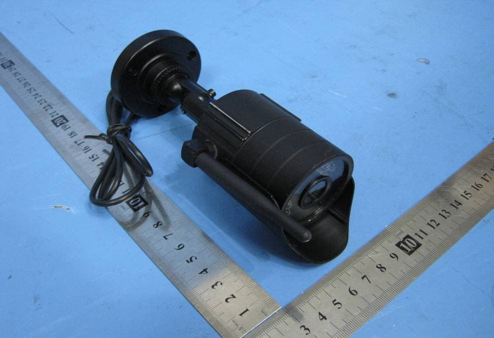
Click to zoom
Application Details
- Equipment Class
- DXX - Part 15 Low Power Communication Device Transmitter
- Date of Grant
- Jun 22, 2010
- Application Purpose
- Original Equipment
- Date of Application
- Jun 22, 2010
- Equipment Note
- WIRELESS CAMERA
- Frequency Range
- 920.00000000 - 920.00000000
- Country
- China
Documents & Files
Document Text
Text extracted from the exhibit documents filed with the FCC. Open a document above to read the original.
Users Manual
For indoor/outdoor use www.jascoproducts.com 1-800 -654-8483 45245 Home Monitoring Wireless Add-on Color Camera User Manual Indoor | Outdoor 2 Table of Contents Product Features .................................................................... 3 Package Contents .................................................................. 4 Choosing A Camera Mounting Location ..................... 4 Long Range Night Vision .................................................... 6 Multi-Camera Systems ........................................................ 6 Camera Channel Selection ................................................ 7 Installation ................................................................................. 8 Troubleshooting ....................................................................12 Specifications .........................................................................15 Warranty .................................................................................. 16 FCC Statement ....................................................................... 17 3 Thank you for purchasing the GE Wireless Add-on Color Camera. This product is intended for use as an add-on camera for the GE Home Monitoring Surveillance Systems. Please review these instructions carefully before attempting to operate the camera. PRODUCT FEATURES • Weather resistant metal camera casing, designed for outdoor use. • Black anodized finish prevents rust and unwanted reflections • Long Range Night Vision — high-powered LED’s allow you to see up to 60ft. in the dark. • Vandal resistant bracket hides cables. • Adjustable sun shield to minimize glare. • Multi-axis adjustment bracket allows you to mount the camera at almost any angle. • Adjustable antenna. • “WiFi” friendly—won’t interfere with home wireless networks. Wirelessly transmits audio and video up to 200 ft. (unobstructed line of sight.) • UL approved power cable. 4 PACKAGE CONTENTS Please check and identify all the parts before proceeding with the installation. 1. Wireless Add-on Color Camera 2. Wall mounting hardware (3 screws, 3 plastic anchors) 3. AC adapter 4. Adjustment wrench CHOOSING A CAMERA MOUNTING LOCATION The Wireless Add-on Color Camera is desiged to be mounted to a wall. It is suitable for indoor or outdoor use. When choosing a mounting location, please be advised: • The wireless camera must be used with a GE Wireless Home Monitoring system. The location of the GE Wireless Receiver or monitor may affect where you mount the camera. • This camera is designed to be reliable for outdoor use; however its flexible design allows it to be used indoors as well. It is expecially suited for viewing large areas in low or no light. • If using outdoors, take time to first consider how you will route the cable back the power adapter. The mounting bracket routes the cable through the bracket providing a vandal-resistant design. There is a slot located at the base of the 5 mounting plate so that the cable can exit the cable ran on the outdoor surface. The cable can also be routed out the bracket and along a wall and/or ceiling keeping it hidden/protected. • The universal multi-axis bracket allows you to mount at almost any angle. • DO NOT position the camera so that it points directly into the sun or any bright light as this may cause damage to the camera. • Avoid positioning the camera so that it is viewing areas where half of the area is in bright sunlight and the other half is dark, such as the shadow of a building. All types of cameras have difficulty “seeing” into areas of such divergent light levels. • In low light conditions, the camera will automatically activate its high-powered Infrared (IR) LED’s and switch the camera to Long Range Night Vision mode. Long Range Night Vision viewing distance can be up to 60ft, and will be viewed in B/W. • The included AC adapter must be positioned no farther than 8’ from an AC outlet. Do not use the supplied adapter outside. If you need to extend the AC adapter cable, 12 ft. extensions are available by contacting Technical Support at 800-654-8483. 6 • The Camera has an unobstructed wireless transmission range up to 200 ft. from the receiver. Transmission distance indoors is reduced due to interior walls, wiring, household fixtures and metal plumbing. LONG RANGE NIGHT VISION The 45245 Wireless Color Camera features Long Range Night Vision tech- nology. Objects and images can be seen in little or no light up to 60 ft. The camera uses a special image sensor that automatically detects available light levels. It turns on/off the high-powered Infrared (IR) LEDs on the front of the camera. These LEDs provide artificial light that allows the camera to ‘see’ in the dark. Night Vision will appear as a Black and White image. When the image sensor detects enough light, color will return to the images. MULTI-CAMERA SYSTEMS The Wireless Add-on Color Camera is designed as an add-on camera to work only with a variety of GE 20 Infrared (IR) LEDs Sensor 7 Wireless Camera Systems - 45234, 45236, 45239, 45246. Each system can accept a maximum of two cameras. CAMERA CHANNEL SELECTION Each wireless camera must be assigned to a specific channel (1 or 2) through the use of a slide switch located on the inside of the camera housing. First slide off the sun shield and then unscrew the lens from the camera. The receiver or monitor must have its channel selection set to the same corresponding number. In a two camera system, one camera is set to Channel 1 and the other is set to Channel 2. The receiver or monitor must be set to the 2 camera position in order to view both cameras alternately (see receiver or monitor manuals for specific channel selection requirements). Channel Selection switch 2 1 8 INSTALLATION Wall Mount or Ceiling Mount — you will need: - Drill - 3/8" Drill bit (if running cable thru wall or ceiling) - 1/8" drill bit (for drilling screw pilot holes if mounting into wood or non-brick material) - 3/16" drill Bit (for dr…
Text truncated - open the document above for the full version.
Cover Letter(s)
RDI Technology (Shenzhen) Co., Ltd FCC ID: SJ8-CA360 POWER OF ATTORNEY Jun 17 ,2010 Federal Communications Commission Authorization and Evaluation Division 7435 Oakland Mills Road Columbia, MD 21046 To Whom It May Concern: We, the undersigned, hereby authorize Waltek Services (ShenZhen) Co., Ltd. (Philo Zhong) on our behalf, to apply to the Federal Communications Commission on our equipment. Any and all acts carried out by Waltek Services (ShenZhen) Co., Ltd. (Philo Zhong) on our behalf shall have the same effect as acts of our own. This authorization expires on Jun 18 , 2011. This is to advise that we are in full compliance with the Anti-Drug Abuse Act. We, RDI Technology (Shenzhen) Co., Ltd., are not subject to a denial of federal benefits pursuant to Section 5301 of the Anti-Drug Act of 1988, 21 USC853a, and no party to the application is subject to a denial of federal benefits pursuant to that section. Sincerely, RDI Technology (Shenzhen) Co., Ltd ------------------------------- Engineering Manager
External Photos
2.1 EUT - Front View 2.2 EUT - Back View
ID Label/Location Info
2 FCC ID Label This device complies with Part 15 of the FCC Rules. Operation is subject to the following two conditions: (1) this device may not cause harmful interference, and (2) this device must accept any interference received, including interference that may cause undesired operation The Label must not be a stick-on paper. The Label on these products must be permanently affixed to the product and readily visible at the time of purchase and must last the expected lifetime of the equipment not be readily detachable. Proposed Label Location on EUT EUT Bottom View/proposed FCC Mark Location FCC ID:SJ8-CA360 This device complies with Part 15 of the FCC Rules. Operation is subject to the following two conditions: (1) this device may not cause harmful interference, and (2) this device must accept any interference received, including interference that may cause undesired operation
ID Label/Location Info
FCC ID Label Sample for Model: CA360 FCC ID : SJ8-CA360 This device complies with Part 15 of the FCC Rules. Operation is subject to the following two conditions:(1)this device may not cause harmful interference, and (2) this device must accept any interference received, including interference that may cause undesired operation.
Internal Photos
2.1 PCB1 - Front View 2.2 PCB1 - Back View 2.3 PCB2 - Front View 2.4 PCB2 - Back View 2.5 PCB3 - Front View 2.6 PCB3 - Back View
Operational Description
CA330 Wireless Camera Nov, 29th, 2007 Architecture CA360 Wireless camera includes high quality video and audio components. When combined with a RDI Wireless Video Monitor/Receiver, you have an ideal combination for watching the baby, monitoring the porch, pets, yard or the pool. It is also suite to many small business applications. CA330 wireless camera hardware architecture is show in Block diagram 1> The camera is base on a single-chip COMS camera sensor (OV7949) provide a high quality video, built-in an audio microphone, auto turn on/off IR LED for night vision and audio alert when audio volume over preset level. 2> The 900MHz TX module is assigned to transmit the video and audio signal. 3> MCU (Micro control unit) operates periodically. Including scan the switch to select the RF module channel and audio detected control
Test Report
RDI Technology (Shenzhen) Co., Ltd FCC ID: SJ8-CA360 FCC TEST REPORT Ref No.: WT10051918-S-E-F Page 1 of 34 FCC ID : SJ8-CA360 Applicant : RDI Technology (Shenzhen) Co., Ltd. Address : Building C1 Xingtang Industrial Park,East Baishixia, Fuyong,Baoan, Shenzhen,PRC. Equipment Under Test (EUT) : Product description :Wireless Camera Model No. :CA360 (45245) Modulation : FSK Standards : FCC 15 Paragraph 15.249 Date of Test : June 17, 2010 Project Engineer : Olic.huang Reviewed By : Prepared By: Waltek Services (Shenzhen) Co., Ltd. 1/F, Fukangtai Building, West Baima Rd., Songgang Street, Baoan District, Shenzhen 518105, China Tel :+86-755-27553488 Fax:+86-755-27553868 RDI Technology (Shenzhen) Co., Ltd FCC ID: SJ8-CA360 Ref No.: WT10051918-S-E-F Page 2 of 34 2 Contents Page 1 COVER PAGE ......................................................................................................................................................... 1 2 CONTENTS .............................................................................................................................................................. 2 3 TEST SUMMARY ................................................................................................................................................... 4 4 GENERAL INFORMATION.................................................................................................................................. 5 4.1 CLIENT INFORMATION........................................................................................................................................ 5 4.2 GENERAL DESCRIPTION OF E.U.T....................................................................................................................... 5 4.3 DETAILS OF E.U.T. ............................................................................................................................................. 5 4.4 DESCRIPTION OF SUPPORT UNITS....................................................................................................................... 5 4.5 STANDARDS APPLICABLE FOR TESTING.............................................................................................................. 5 4.6 TEST FACILITY.................................................................................................................................................... 6 4.7 TEST LOCATION.................................................................................................................................................. 6 5 EQUIPMENT USED DURING TEST ................................................................................................................... 7 6 CONDUCTED EMISSION TEST .......................................................................................................................... 8 6.1 TEST EQUIPMENT................................................................................................................................................ 8 6.2 TEST PROCEDURE............................................................................................................................................... 8 6.3 CONDUCTED TEST SETUP................................................................................................................................... 9 6.4 EUT OPERATING CONDITION............................................................................................................................. 9 6.5 CONDUCTED EMISSION LIMITS......................................................................................................................... 10 6.6 CONDUCTED EMISSION TEST RESULT............................................................................................................... 10 6.7 CONDUCTED EMISSION TEST SETUP VIEW........................................................................................................ 12 7 RADIATION EMISSION TEST........................................................................................................................... 13 7.1 TEST EQUIPMENT.............................................................................................................................................. 13 7.2 MEASUREMENT UNCERTAINTY......................................................................................................................... 13 7.3 TEST PROCEDURE............................................................................................................................................. 13 7.4 RADIATED TEST SETUP..................................................................................................................................... 14 7.5 SPECTRUM ANALYZER SETUP........................................................................................................................... 14 7.6 CORRECTED AMPLITUDE & MARGIN CALCULATION........................................................................................ 15 7.7 SUMMARY OF TEST RESULTS............................................................................................................................ 15 7.8 EUT OPERATING CONDITION........................................................................................................................... 16 7.9 RADIATED EMISSIONS LIMIT............................................................................................................................ 16 7.10 RADIATED EMISSIONS TEST RESULT................................................................................................................ 17 8 PERIODIC OPERATION..................................................................................................................................... 20 9 ANTENNA REQUIREMENT............................................................................................................................... 23 10 20-DB BANDWIDTH............................…
Text truncated - open the document above for the full version.
Test Setup Photos
Conducted Emission Test Setup View Test Setup Front View Test Setup Back View Radiation Emission Test View For 30MHz-1000MHz Radiation Emission Test View For 1GHz-10GHz
Contact Information
Applicant
Yuan Mike(Vice General Manager)
Test Firm
Waltek Services(Shenzhen) Co., Ltd.Philo zhong
Technical Specifications
| # | Rule Parts | Frequency Range | Power Output |
|---|---|---|---|
| 2 | 15C | 920 MHz - 920 MHz | - |
Other Applications from RDI Technology (Shenzhen) Co., Ltd.
SJ8-VC160
Jan 08, 2026Wireless Camera
Equipment Class
NII - Unlicensed National Information Infrastructure TXSJ8-M125
Jan 07, 2026Wireless Monitor
Equipment Class
NII - Unlicensed National Information Infrastructure TXSJ8-VC46
Dec 10, 2025Wireless Camera
Equipment Class
DTS - Digital Transmission System
SJ8-M124EI
Aug 08, 2024Wireless Monitor
Equipment Class
DTS - Digital Transmission System
SJ8M514
Dec 14, 2023Wireless 5 LCD Monitor
Equipment Class
DTS - Digital Transmission System