SJ8-CA670QNDIGITAL WIRELESS CAMERA
RDI Technology (Shenzhen) Co., Ltd.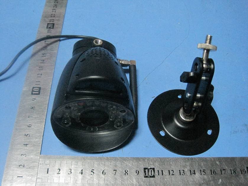
Click to zoom
Application Details
- Equipment Class
- DSS - Part 15 Spread Spectrum Transmitter
- Date of Grant
- May 14, 2012
- Application Purpose
- Original Equipment
- Date of Application
- May 14, 2012
- Equipment Note
- DIGITAL WIRELESS CAMERA
- Frequency Range
- 2402.00000000 - 2480.00000000
- Country
- China
Documents & Files
Document Text
Text extracted from the exhibit documents filed with the FCC. Open a document above to read the original.
Users Manual
PORTABLE DIGITAL WIRELESS MONITORING SYSTEM INSTRUCTION MANUAL CAMERA: CA670QN MONITOR:M370M 1 Welcome! Thank you for purchasing the wireless video monitor. Before you start, make sure you have the contents listed below. Contents The system comes with the following components: • Camera X1 • Video Monitor X1 • Charging cradle for video monitor X1 • Driver CD X1 • Power adapter for camera X1 • Power adapter for video monitor X1 • Mini USB cable X1 • User’s manual X1 • Hardware kit X1 Camera Video Monitor with Charging Cradle Driver CD Power Adaptor for Camera* Power Adaptor for Video Monitor* Mini USB Cable * The shape of power adaptor may not be exactly as shown Check your package to confirm that you have received the complete system, including all components shown above. 2 Features • Digital wireless technology provides excellent image quality and clarity • Interference free, secure and private signal • Up to 450ft wireless transmission range ① • Listen in with exceptional sound clarity • Two-way audio communication • Safety warning feature notifies you when out of range • System expandable up to 4 cameras ② • Micro SD card recording • Timer Function • USB output for monitoring on PC ① Maximum open space transmission range. The actual range is dependent upon building materials and other obstructions in path of wireless signal. ② Additional cameras sold separately. Camera Features • Night vision allows for low light viewing up to 15 feet / 4.5 meters ③ • Two-way controlled night light • Built-in microphone and speaker • Camera can be battery operated for true portable wireless operation • Two-way controlled lullabies • Adjustable sensitivity for audio alarm • Weatherproof for outdoor use ③ IR illumination range of 15ft./4.5m under ideal conditions. Objects at or beyond this range may be partially or completely obscured, depending on the camera application. Receiver Features • 3.5” color LCD monitor/receiver with superior image quality • Rechargeable lithium polymer battery for true portability • Convenient receiver cradle included • Audio level indicator and alarm • Temperature display on LCD screen 3 Overview Video Monitor Overview 4 Using the joystick to navigate menus The joystick allows you to navigate through the video monitor menus. 5 Camera Overview 1). Lens: Camera lens. 2). Microphone: Built-in microphone underneath camera body. 3). PIR Sensor: Passive IR motion sensor for more accurate motion recording. 4). Speaker: Speaker for two-way audio. 5). Night Vision IR: Night vision IR LEDs used for viewing in complete darkness. 6). Pair: Pairing button. For more details, see “Appendix C: Adding Cameras” on page 33. 7). Antenna: Wireless antenna. 8). Power Cable: Connect the included power adapter to the cable extending from the camera. Note: This camera includes an Auto Mechanical IR Cut Filter. When the camera changes between day/night lighting, an audible clicking noise may be heard coming from the camera. This clicking is normal, and indicates that the camera filter is working. 6 OSD Overview The video monitor displays the following icons during normal use. The table below summarizes the video monitor icons, and what they mean. 7 8 Basic Setup Step 1 of 2: Powering on the camera Connect the power adapter to a power outlet and to the camera. Step 2 of 2: Powering on the Video Monitor 1. Connect the power adapter to a power outlet, and to the video monitor directly or charging cradle (ensure the video monitor firmly rests on the cradle). The video monitor’s charging LED indicator glows red to indicate charging is in progress. NOTE: It requires 6 hours to fully charge the rechargeable batteries. 2. Slide the power switch to ON position. The video monitor will automatically scan for cameras in range. Testing your setup It is recommended that you test your camera setup before permanent installation so that you get the best picture and sound quality from your video monitor. Test the camera and video monitor reception: 1. Place the camera and video monitor in two different rooms. 2. Have one person monitor the signal strength on the video monitor. 3. If the signal strength is low, have a second person move the camera to different locations of the room to find the optimal placement location. Test the camera volume level: 1. Have a person with the video monitor press and hold the TALK button to confirm the volume level from the camera. Have the other person adjust the volume dial on the camera as required. 2. The person holding the video monitor can determine if the camera needs to move to a different location of the room for better sound clarity. 9 Installing the camera Before you install the camera, plan where and how it will be positioned, and where you will route the cable that connects the camera to the power adapter. • Before starting permanent installation, verify its performance by observing the image on a monitor when camera is positioned in the same location/position where it will be permanently installed. • The cameras are pre-paired so they work out of the box. Each camera has a channel number sticker indicating what channel they are paired to. To manually pair your cameras, see “Appendix C: Adding Cameras” on page 33. Installation Warnings: • Mount the camera indoors or outdoors. For outdoor installation, mount it in a sheltered place where it is not directly exposed to rain or snow. • Aim the Cameras to best optimize the viewing area: Select a location for the camera that provides a clear view of the area you want to monitor, which is free from dust, and is not in line-of-sight to a strong light source or direct sunlight. • Place the camera within 21 feet (6.5 meters) of the area you wish to monitor for motion during night time. This allows for optimal motion detection. • Avoid installing the cameras where there are thick walls or obstructions between the Cameras and the Receiver • Select a location for the camera that has an ambient temperature between 14°F~104°F (-10°C ~ 40°…
Text truncated - open the document above for the full version.
Cover Letter(s)
RDI Technology (Shenzhen) Co., Ltd. Federal Communications Commission Authorization and Evaluation Division Confidentiality Request regarding application for certification of FCC ID: SJ8-CA670QN. Pursuant to Sections 0.457 and 0.459 of the Commission’s Rules, we hereby request confidential treatment of information accompanying this application as outlined below: Exhibit Type File Name Schematics Block Diagram Operational Description SJ8-CA670QN_SCH.pdf SJ8-CA670QN_BlockDiagram.pdf SJ8-CA670QN_CircuitDescription.pdf The above materials contain trade secrets and proprietary information not customarily released to the public. The public disclosure of these materials may be harmful to the applicant and provide unjustified benefits to its competitors. The applicant understands that pursuant to Section 0.457 of the Rules, disclosure of this application and all accompanying documentation will not be made before the date of the Grant for this application. Sincerely, ---------------------------- Tony Zhou / Engineering Manager
Cover Letter(s)
RDI Technology (Shenzhen) Co., Ltd. FCC ID: SJ8-CA670QN POWER OF ATTORNEY May 3, 2012 Federal Communications Commission Authorization and Evaluation Division 7435 Oakland Mills Road Columbia, MD 21046 To Whom It May Concern: We, the undersigned, hereby authorize Waltek Services (ShenZhen) Co., Ltd. (Philo Zhong) on our behalf, to apply to the Federal Communications Commission on our equipment. Any and all acts carried out by Waltek Services (ShenZhen) Co., Ltd. (Philo Zhong) on our behalf shall have the same effect as acts of our own. This authorization expires on May 2, 2013. This is to advise that we are in full compliance with the Anti-Drug Abuse Act. We, RDI Technology (Shenzhen) Co., Ltd., are not subject to a denial of federal benefits pursuant to Section 5301 of the Anti-Drug Act of 1988, 21 USC853a, and no party to the application is subject to a denial of federal benefits pursuant to that section. Sincerely, RDI Technology (Shenzhen) Co., Ltd. ------------------------------- Tony Zhou / Engineering Manager
External Photos
2.1 Product View 2.2 EUT – Appearance View
ID Label/Location Info
FCC ID Label Sample for Model: CA670QN FCC ID: SJ8-CA670QN This device complies with Part 15 of the FCC Rules. Operation is subject to the following two conditions: (1) this device may not cause harmful interference, and (2) this device must accept any interference received, including interference that may cause undesired operation.
ID Label/Location Info
Page: 57 of 57 RDI Technology (Shenzhen) Co., Ltd. FCC ID: SJ8-CA670QN The results shown in this test report refer only to the sample(s) tested , This Test report cannot be reproduced, except in full, without prior written permission of the Company. WALTEK SERVICES Reference No.: WT12042462-F-S-F 17 FCC Label This device complies with Part 15 of the FCC Rules. Operation is subject to the following two conditions: (1) this device may not cause interference, and (2) this device must accept any interference, including interference that may cause undesired operation of the device. The Label must not be a stick-on paper. The Label on these products must be permanently affixed to the product and readily visible at the time of purchase and must last the expected lifetime of the equipment not be readily detachable. Proposed Label Location on EUT EUT Top View/ proposed FCC Label Location FCC ID: SJ8-CA670QN This device complies with Part 15 of the FCC Rules. Operation is subject to the following two conditions: (1) this device may not cause harmful interference, and (2) this device must accept any
Internal Photos
2.1 EUT – Open View 2.2 EUT - PCB View 2.3 RF Module - View
Test Report
Page: 1 of 57 FCC TEST REPORT The results shown in this test report refer only to the sample(s) tested , This Test report cannot be reproduced, except in full, without prior written permission of the Company. WALTEK SERVICES Reference No.: WT12042462-F-S-F FCC ID : SJ8-CA670QN Applicant : RDI Technology (Shenzhen) Co., Ltd. Address : Building C1 Xingtang Industrial Park, East Baishixia, Fuyong, Baoan, Shenzhen, China Equipment Under Test (EUT) : Product Name : Digital Wireless Camera Model No. : CA670QN Standards : FCC CFR47 Part 15 Section 15.247:2010 Date of Test : April 21 ~ April 28, 2012 Date of Issue : May 4, 2012 Test Engineer : Hunk yan / Engineer Reviewed By : Philo zhong / Manager Test Result : PASS Prepared By: Waltek Services (Shenzhen) Co., Ltd. 1/F, Fukangtai Building, West Baima Rd., Songgang Street, Baoan District, Shenzhen 518105, China Tel :+86-755-27553488 Fax:+86-755-27553868 Page: 2 of 57 RDI Technology (Shenzhen) Co., Ltd. FCC ID: SJ8-CA670QN The results shown in this test report refer only to the sample(s) tested , This Test report cannot be reproduced, except in full, without prior written permission of the Company. WALTEK SERVICES Reference No.: WT12042462-F-S-F 2 Test Summary Test Items Test Requirement Result Radiated Spurious Emissions (9kHz to 25GHz) 15.205(a) 15.209 15.247(d) PASS Conduct Emission 15.207 PASS 20dB Bandwidth 15.247(a)(1) PASS Maximum Peak Output Power 15.247(b)(1) PASS Frequency Separation 15.247(a)(1) PASS Number of Hopping Frequency 15.247(a)(1)(iii) PASS Dwell time 15.247(a)(1)(iii) PASS Maximum Permissible Exposure (Exposure of Humans to RF Fields) 1.1307(b)(1) PASS Page: 3 of 57 RDI Technology (Shenzhen) Co., Ltd. FCC ID: SJ8-CA670QN The results shown in this test report refer only to the sample(s) tested , This Test report cannot be reproduced, except in full, without prior written permission of the Company. WALTEK SERVICES Reference No.: WT12042462-F-S-F 3 Contents Page 1 COVER PAGE ........................................................................................................................................................ 1 2 TEST SUMMARY .................................................................................................................................................. 2 3 CONTENTS............................................................................................................................................................. 3 4 GENERAL INFORMATION ................................................................................................................................ 5 4.1 CLIENT INFORMATION........................................................................................................................................... 5 4.2 GENERAL DESCRIPTION OF E.U.T. ........................................................................................................................ 5 4.3 DETAILS OF E.U.T................................................................................................................................................. 5 4.4 DESCRIPTION OF SUPPORT UNITS.......................................................................................................................... 5 4.5 STANDARDS APPLICABLE FOR TESTING................................................................................................................ 5 4.6 TEST FACILITY...................................................................................................................................................... 6 4.7 TEST LOCATION.................................................................................................................................................... 6 5 EQUIPMENT USED DURING TEST .................................................................................................................. 7 6 CONDUCTED EMISSION .................................................................................................................................... 9 6.1 E.U.T. OPERATION................................................................................................................................................ 9 6.2 EUT SETUP......................................................................................................................................................... 10 6.3 CONDUCTED EMISSION TEST RESULT................................................................................................................. 10 6.4 PHOTOGRAPH – CONDUCTED EMISSION TEST SETUP.......................................................................................... 13 7 RADIATED SPURIOUS EMISSIONS ............................................................................................................... 14 7.1 EUT OPERATION :............................................................................................................................................... 14 7.2 MEASUREMENT UNCERTAINTY........................................................................................................................... 14 7.3 TEST SETUP......................................................................................................................................................... 15 7.4 SPECTRUM ANALYZER SETUP............................................................................................................................. 16 7.5 TEST PROCEDURE................................................................................................................................................ 17 7.6 CORRECTED AMPLITUDE & MARGIN CALCULATION........................................................................................... 17 7.7 SUMMARY OF TEST RESULTS.............................................................................................................................. 18 7.8 PHOTOGRAPH – RADIATION SPURIOUS EMISSION TEST SETUP...............…
Text truncated - open the document above for the full version.
Test Setup Photos
2.1 Photograph – Radiation Spurious Emission Test Setup Below 1GHz Above 1GHz 2.2 Photograph – Conducted Emission Test Setup
Contact Information
Applicant
Yuan Mike(Vice General Manager)
Test Firm
Waltek Services(Shenzhen) Co., Ltd.Philo zhong
Technical Specifications
| # | Rule Parts | Frequency Range | Power Output |
|---|---|---|---|
| 1 | 15C | 2.40 GHz - 2.48 GHz | 43.00 mW |
Other Applications from RDI Technology (Shenzhen) Co., Ltd.
SJ8-VC160
Jan 08, 2026Wireless Camera
Equipment Class
NII - Unlicensed National Information Infrastructure TXSJ8-M125
Jan 07, 2026Wireless Monitor
Equipment Class
NII - Unlicensed National Information Infrastructure TXSJ8-VC46
Dec 10, 2025Wireless Camera
Equipment Class
DTS - Digital Transmission System
SJ8-M124EI
Aug 08, 2024Wireless Monitor
Equipment Class
DTS - Digital Transmission System
SJ8M514
Dec 14, 2023Wireless 5 LCD Monitor
Equipment Class
DTS - Digital Transmission System