SJ8-M710DIGITAL WIRELESS MONITOR
RDI Technology (Shenzhen) Co., Ltd.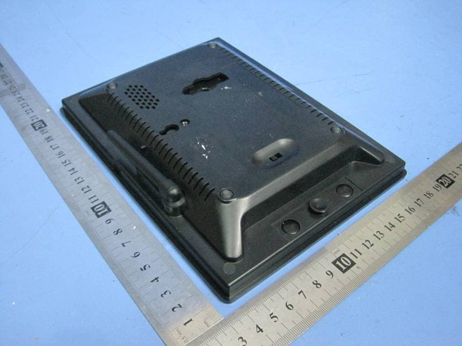
Click to zoom
Application Details
- Equipment Class
- DSS - Part 15 Spread Spectrum Transmitter
- Date of Grant
- Aug 29, 2010
- Application Purpose
- Original Equipment
- Date of Application
- Aug 29, 2010
- Equipment Note
- DIGITAL WIRELESS MONITOR
- Frequency Range
- 2402.00000000 - 2478.00000000
- Country
- China
Documents & Files
Document Text
Text extracted from the exhibit documents filed with the FCC. Open a document above to read the original.
Users Manual
DIGITAL WIRELESS 7” LCD MONITORING SYSTEM WITH SD CARD RECORDING INSTRUCTION MANUAL Manual 1 Features • Digital wireless technology provides excellent image quality and clarity • Interference free, secure and private signal • Up to 300ft wireless transmission range ① • Two-way audio communication • SD card recording • Safety warning feature notifies you when out of range • System expandable up to 4 cameras ② ① Maximum open space transmission range. The actual range is dependent upon building materials and other obstructions in path of wireless signal. ② Additional cameras sold separately. Camera Features • VGA resolution camera • Night vision allows for low light viewing up to 15 feet / 4.5 meters ③ • Built-in microphone • Weatherproof for outdoor use • PIR Sensor for motion detection ③ IR illumination range of 15ft./4.5m under ideal conditions. Objects at or beyond this range may be partially or completely obscured, depending on the camera application. Receiver Features • 7” color LCD monitor/receiver with superior image quality • Auto recording, manual recording and schedule recording • Remote control for receiver portable operation • Displaying stored pictures in scan mode (screen saver) • Can be desktop stand or wall mounted • Supports quad image view Getting Started The system comes with the following components: Check your package to confirm that you have received the complete system, including all components shown above. 2 Wireless Receiver Front Controls 1. LCD Screen – Displays video from the camera(s) or displays system operations. 2. Indication LEDs – Indicates the status of the system. There are 4 indication LEDs: NEW: Indicates new recorded video. FULL: Indicates that the SD card is full of memory. It is only available when Overwrite is disabled. SCAN: Indicates that the receiver is in scan mode (screen saver). AUTO REC: Indicates that the receiver is in auto recording mode. Receiver starts to record when there is motion detection in camera side. Back Controls 3. Receiver Antenna – receives & sends signals from or to the camera(s). Adjust the antenna to vertical position when the signal reception is not good. 4. Speaker – Produces the sound transmitted from the camera(s). 5. Hanging Hole – Insert the screw which is already installed on a wall into the hole, and push the receiver downwards to hang the receiver on the wall. 6. Wall Mounting Hole – Screw the wall mounting bracket to the hole, then fix the bracket to the wall to mount the receiver on the wall. 7. MENU Button – Press to access the receiver menu. Press the button again to exit. 8. Joystick – In viewing mode, press down the joystick to enter playback interface for recorded videos. In quad mode, push the joystick to a certain number to view the image from the corresponding camera in full screen mode. In menu mode, use the joystick (UP/DOWN/LEFT/RIGHT ▲▼◄► arrows) for system setting or menu selection, and press it down it to confirm the selection or setting. In playback mode, use the joystick to play/pause, stop, forward, backward, etc. 3 9. TALK Button – Press down and hold this button to talk back to the camera which’s image is displayed on the screen. 10. Microphone – Receives sounds from the area near the receiver and transmits sound from the receiver to the camera (only when TALK Button is pressed down and held). 11. Power Slide Switch – Slide the switch to ON or OFF position to switch on/off the receiver. 12. DC 5V Power Input – Connect the included DC 5V power adaptor to power the receiver. 13. SD Card Slot – Insert SD card to this SD card slot for both video and audio recording. 14. A/V Out Port – Connect the included A/V cable to view video from the receiver on a TV or monitor, or record to a VCR/DVR. 15. Receiver Stand – Enables the receiver to stand on a flat surface, such as a table or countertop. You can also adjust the viewing angle by rotating the stand. Wireless Receiver Installation 1. Before receiver installation, choose one installation method from below 3 methods: 1). Desktop or table stand. For this method, you only need to place the receiver on a desktop and use the supplied receiver stand. 2). Hung on the screw which is fixed on a wall. Decide where to hang the receiver first. Make sure the range between the position and the nearest power output port is no more than 5 feet. Drill a hole on the wall where you decide to hang the receiver, insert one plastic anchor and fix a screw into the plastic anchor. Now the receiver can be hung on the screw (receiver back control number ⑤). 3). Wall mounting Decide where to install the receiver first. Make sure the range between the position and the nearest power output port is no more than 5 feet. Screw supplied wall mounting bracket to the receiver (receiver back control number ⑥), then drill 3 holes on the wall where you decide to install the receiver, then insert 3 plastic anchors and fix the wall mounting bracket to the anchors with supplied screws. 2. After the receiver is well positioned, plug the AC adaptor power output cable into the 5V POWER input of the receiver, and plug the power plug into a wall outlet or surge protector. 3. If you wish to view the receiver images on a larger screen, connect one end of the included AV cable to the AV output of receiver, and connect the other end to the Video IN (Yellow) and Audio IN (White) ports on the TV, VCR or other viewing/recording devices. Note: When outputting Audio/Video to TV, etc, press the AV button on the remote control to output audio and video to TV. The receiver installation is now completed. 4 Wireless Camera Front & Side Controls 1. Camera Antenna – Sends & receives signals to or from the receiver. 2. AC Adaptor Jack – Plug the AC adaptor to the jack for camera’s power supply. 3. Wall Mounting Bracket – Use the bracket to mount the camera on a wall or other flat surfaces. 4. IR LEDs – Infrared LEDs provide viewing in no/low light conditions 5. Lens – Catches the video in front of the lens and …
Text truncated - open the document above for the full version.
Cover Letter(s)
RDI Technology (Shenzhen) Co., Ltd FCC ID: SJ8-M710 POWER OF ATTORNEY Aug 17 ,2010 Federal Communications Commission Authorization and Evaluation Division 7435 Oakland Mills Road Columbia, MD 21046 To Whom It May Concern: We, the undersigned, hereby authorize Waltek Services (ShenZhen) Co., Ltd. (Philo Zhong) on our behalf, to apply to the Federal Communications Commission on our equipment. Any and all acts carried out by Waltek Services (ShenZhen) Co., Ltd. (Philo Zhong) on our behalf shall have the same effect as acts of our own. This authorization expires on Aug 18 , 2011. This is to advise that we are in full compliance with the Anti-Drug Abuse Act. We, RDI Technology (Shenzhen) Co., Ltd., are not subject to a denial of federal benefits pursuant to Section 5301 of the Anti-Drug Act of 1988, 21 USC853a, and no party to the application is subject to a denial of federal benefits pursuant to that section. Sincerely, RDI Technology (Shenzhen) Co., Ltd ------------------------------- Engineering Manager
External Photos
2.1 EUT - Front View 2.2 EUT - Back View
ID Label/Location Info
RDI Technology (Shenzhen) Co., Ltd FCC ID: SJ8-M710 Page 50 of 50 Ref No.: WT10083237-S-E-F FCC ID Label This device complies with Part 15 of the FCC Rules. Operation is subject to the following two conditions:(1)this device may not cause harmful interference, and (2) this device must accept any interference received, including interference that may cause undesired operation. The Label must not be a stick-on paper. The Label on these products must be permanently affixed to the product and readily visible at the time of purchase and must last the expected lifetime of the equipment not be readily detachable. Proposed Label Location on EUT EUT Top View/ proposed FCC Label Location FCC ID: SJ8-M710 This device com plies with Part 15 of the FCC Rules. Operation is subject to the following two conditions:(1)this device ma y not cause harmful interference,and (2) this device must accept any interference received, including interference that may cause undesired operation.
ID Label/Location Info
FCC ID Label Sample for Model: M710 FCC ID : SJ8-M710 This device complies with Part 15 of the FCC Rules. Operation is subject to the following two conditions:(1)this device may not cause harmful interference, and (2) this device must accept any interference received, including interference that may cause undesired operation.
Internal Photos
2.1 PCB 1 -Front View 2.2 PCB 1 - Back View 2.3 PCB 2 -Front View 2.4 PCB 2-Back View
Operational Description
M710 2.4Ghz Digital Wireless Monitor Architecture: M710 is a low cost and high performance digital Wireless monitor which integrates M-JPEG codec , FHSS base band , RF transceiver ,CMOS sensor color processing unit , ADPCM codec, LCD display engine. The base- band implement a Bluetooth like frequency adaptive hopping technology to prevent being jammed by microwave oven and other 2.4GHz devices. It can co-existence with Bluetooth, WLAN and other 2.4GHz digital-modulated devices. M710 2.4Ghz Digital Baby Monitor hardware architecture is show in Block diagram z Auto ACK & retransmit On the air max. data rate 2Mpbs z Software selectable channel form 2400MHz to 2525MHz (125 Selectable channels) z Intelligent frequency hopping (change RF channel automatically) z Support AV Out z Support Sound level indicate nRF24L01 is a single chip radio transceiver for the world wide 2.4 -2.5 GHz ISM band. The transceiver consists of a fully integrated frequency synthesizer, a power amplifier, a crystal oscillator, a demodulator, modulator and Enhanced ShockBurst™ protocol engine. Output power, frequency channels, and protocol setup are easily programmable through a SPI interface. Current consumption is very low, only 9.0mA at an output power of -6dBm and 12.3mA in RX mode. Built-in Power Down and Standby modes makes power saving easily realizable. A simplified block diagram of the nRF24L01 is shown in figure 2 Figure 2 : nRF24L01 Block Diagram Packet Handling Methods nRF24L01 has the following Packet Handling Methods: ShockBurst™ (compatible with nRF2401, nRF24E1, nRF2402 and nRF24E2 with 1Mbps data rate, see page 24) Enhanced ShockBurst™ ShockBurst™ ShockBurst™ makes it possible to use the high data rate offered by nRF24L01 without the need of a costly, high-speed microcontroller (MCU) for data processing/clock recovery. By placing all high speed signal processing related to RF protocol on-chip, nRF24L01 offers the application microcontroller a simple SPI compatible interface, the data rate is decided by the interface-speed the micro controller itself sets up. By allowing the digital part of the application to run at low speed, while maximizing the data rate on the RF link, ShockBurst™ reduces the average current consumption in applications. In ShockBurst™ RX, IRQ notifies the MCU when a valid address and payload is received respectively. The MCU can then clock out the received payload from an nRF24L01 RX FIFO. In ShockBurst™ TX, nRF24L01 automatically generates preamble and CRC, see Table 12. IRQ notifies the MCU that the transmission is completed. All together, this means reduced memory demand in the MCU resulting in a low cost MCU, as well as reduced software development time. nRF24L01 has a three level deep RX FIFO (shared between 6 pipes) and a three level deep TX FIFO. The MCU can access the FIFOs at any time, in power down mode, in standby modes, and during RF packet transmission. This allows the slowest possible SPI interface compared to the average datarate, and may enable usage of an MCU without hardware SPI. Enhanced ShockBurst™ Enhanced ShockBurst™ is a packet handling method with functionality that makes bi-directional link protocol implementation easier and more efficient. In a typical bi-directional link, one will let the terminating part acknowledge received packets from the originating part in order to make it possible to detect data loss. Data loss can then be recovered by retransmission. The idea with Enhanced ShockBurst™ is to let nRF24L01 handle both acknowledgement of received packets and retransmissions of lost packets, without involvement from the microcontroller. Figure 3: nRF24L01 in a star network configuration An nRF24L01 configured as primary RX (PRX) will be able to receive data trough 6 different data pipes, see Figure 3. A data pipe will have a unique address but share the same frequency channel. This means that up to 6 different nRF24L01 configured as primary TX (PTX) can communicate with one nRF24L01 configured as PRX, and the nRF24L01 configured as PRX will be able to distinguish between them. Data pipe 0 has a unique 40 bit configurable address. Each of data pipe 1-5 has an 8 bit unique address and shares the 32 most significant address bits. All data pipes can perform full Enhanced ShockBurst™ functionality. nRF24L01 will use the data pipe address when acknowledging a received packet. This means that nRF24L01 will transmit ACK with the same address as it receives payload at. In the PTX device data pipe 0 is used to received the acknowledge, and therefore the receive address for data pipe 0 has to be equal to the transmit address to be able to receive the acknowledge. See Figure 5 for addressing example. Figure 4: Example on how the acknowledgement addressing is done An nRF24L01 configured as PTX with Enhanced ShockBurst™ enabled, will use the ShockBurst™ feature to send a packet whenever the microcontroller wants to. After the packet has been transmitted, nRF24L01 will switch on its receiver and expect an acknowledgement to arrive from the terminating part. If this acknowledgement fails to arrive, nRF24L01 will retransmit the same packet until it receives an acknowledgement or the number of retries exceeds the number of allowed retries given in the SETUP_RETR_ARC register. If the number of retries exceeds the number of allowed retries, this will show in the STATUS register bit MAX_RT and gives an interrupt. Whenever an acknowledgement is received by an nRF24L01 it will consider the last transmitted packet as delivered. It will then be cleared from the TX FIFO, and the TX_DS IRQ source will be set high. With Enhanced ShockBurst™ nRF24L01 offers the following benefits: Highly reduced current consumption due to short time on air and sharp timing when operating with acknowledgement traffic Lower system cost. Since the nRF24L01 handles all the high-speed link layer operations, like re-transmission of lost packet and generating acknowledgement to received packets, it is no ne…
Text truncated - open the document above for the full version.
Test Report
RDI Technology (Shenzhen) Co., Ltd FCC ID: SJ8-M710 FCC TEST REPORT Page 1 of 50 Ref No.: WT10083237-S-E-F FCC ID : SJ8-M710 Applicant : RDI Technology (Shenzhen) Co., Ltd Address of Applicant : Building C1 Xingtang Industrial Park, East Baishixia, Fuyong, Baoan, Shenzhen, PRC. Equipment Under Test (EUT) : Product description : Digital Wireless Monitor Model No. : M710 Frequency Range : 2402MHz to 2478MHz Standards : FCC 15 Paragraph 15.247 Date of Test : Aug.12,2010 Test Engineer : (Olic huang) Reviewed By : (Philo zhong) PERPARED BY: Waltek Services (Shenzhen) Co., Ltd. 1/F, Fukangtai Building,West Baima Rd.,Songgang Street, Baoan District, Shenzhen 518105,China Tel :+86-755-27553488 Fax:+86-755-27553868 RDI Technology (Shenzhen) Co., Ltd FCC ID: SJ8-M710 Page 2 of 50 Ref No.: WT10083237-S-E-F 2 Contents Page 1 COVER PAGE..........................................................................................................................................................1 2 CONTENTS ..............................................................................................................................................................2 3 TEST SUMMARY....................................................................................................................................................4 4 GENERAL INFORMATION..................................................................................................................................5 4.1 CLIENT INFORMATION............................................................................................................................................5 4.2 GENERAL DESCRIPTION OF E.U.T...........................................................................................................................5 4.3 DETAILS OF E.U.T. .................................................................................................................................................5 4.4 DESCRIPTION OF SUPPORT UNITS...........................................................................................................................5 4.5 STANDARDS APPLICABLE FOR TESTING..................................................................................................................5 4.6 TEST FACILITY........................................................................................................................................................6 4.7 TEST LOCATION......................................................................................................................................................6 4.8 EQUIPMENT USED DURING TEST.............................................................................................................................7 5 CONDUCTED EMISSION TEST ........................................................................................................................10 5.1 TEST EQUIPMENT..................................................................................................................................................10 5.2 TEST PROCEDURE.................................................................................................................................................10 5.3 CONDUCTED TEST SETUP.....................................................................................................................................11 5.4 EUT OPERATING CONDITION...............................................................................................................................11 5.5 CONDUCTED EMISSION LIMITS.............................................................................................................................12 5.6 CONDUCTED EMISSION TEST DATA......................................................................................................................12 5.7 CONDUCTED EMISSION TEST SETUP VIEW............................................................................................................14 6 RADIATION EMISSION TEST...........................................................................................................................15 6.1 TEST EQUIPMENT..................................................................................................................................................15 6.2 MEASUREMENT UNCERTAINTY.............................................................................................................................15 6.3 TEST PROCEDURE.................................................................................................................................................15 6.4 RADIATED TEST SETUP.........................................................................................................................................16 6.5 SPECTRUM ANALYZER SETUP...............................................................................................................................16 6.6 CORRECTED AMPLITUDE & MARGIN CALCULATION............................................................................................17 6.7 SUMMARY OF TEST RESULTS................................................................................................................................17 6.8 EUT OPERATING CONDITION...............................................................................................................................18 6.9 RADIATED EMISSIONS LIMIT ON PARAGRAPH 15.209 ...........................................................................................18 6.10 RADIATED EMISSIONS TEST RESULT................................................................................................................19 6.11 RADIATED EMISSION DATA.............................................................................................................................19 6.11.1 Test mode: continuously recevie mode...............................................................…
Text truncated - open the document above for the full version.
Test Setup Photos
2.1 Conducted Emission Test Setup View Test Front View Test Back View Radiation Emission Test View For 30MHz-1000MHz Radiation Emission Test View For 1GHz-25GHz
Contact Information
Applicant
Yuan Mike(Vice General Manager)
Test Firm
Waltek Services(Shenzhen) Co., Ltd.Philo zhong
Technical Specifications
| # | Rule Parts | Frequency Range | Power Output |
|---|---|---|---|
| 1 | 15C | 2.40 GHz - 2.48 GHz | 38.00 mW |
Other Applications from RDI Technology (Shenzhen) Co., Ltd.
SJ8-VC160
Jan 08, 2026Wireless Camera
Equipment Class
NII - Unlicensed National Information Infrastructure TXSJ8-M125
Jan 07, 2026Wireless Monitor
Equipment Class
NII - Unlicensed National Information Infrastructure TXSJ8-VC46
Dec 10, 2025Wireless Camera
Equipment Class
DTS - Digital Transmission System
SJ8-M124EI
Aug 08, 2024Wireless Monitor
Equipment Class
DTS - Digital Transmission System
SJ8M514
Dec 14, 2023Wireless 5 LCD Monitor
Equipment Class
DTS - Digital Transmission System