SJ8-M900HRDIGITAL WIRELESS MONITOR
RDI Technology (Shenzhen) Co., Ltd.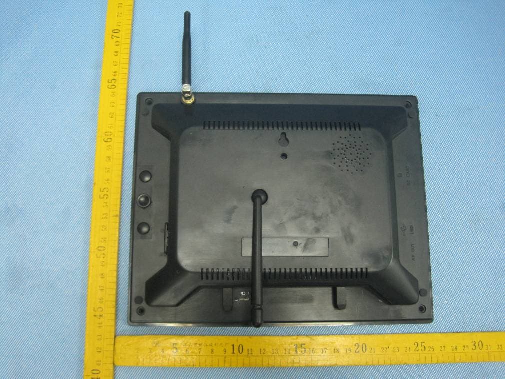
Click to zoom
Application Details
- Equipment Class
- DSS - Part 15 Spread Spectrum Transmitter
- Date of Grant
- Nov 20, 2012
- Application Purpose
- Original Equipment
- Date of Application
- Nov 20, 2012
- Equipment Note
- DIGITAL WIRELESS MONITOR
- Frequency Range
- 2402.00000000 - 2480.00000000
- Country
- China
Documents & Files
Document Text
Text extracted from the exhibit documents filed with the FCC. Open a document above to read the original.
Users Manual
0 DIGITAL WIRELESS 9” LCD MONITORING SYSTEM WITH SD CARD RECORDING INSTRUCTION MANUAL MODEL: CMD6790HR/CMD6771HR M710HR Digital wireless monitor M900HR Digital wireless monitor CA670HR Digital wireless camera 1 Camera Features • VGA resolution camera • Night vision allows for low light viewing up to 40 feet / 12 meters ③ • Built-in microphone • Weatherproof for outdoor use • PIR Sensor for motion detection ③ IR illumination range of 40ft./12m under ideal conditions. Objects at or beyond this range may be partially or completely obscured, depending on the camera application. Receiver Features • RF Chip: Nordic 24L01 • Sensor: MI-360 1/4 Cmos sensor • 850nm IR Led visible distance up to 10m • 9’’ Hannstar TFT Lcd Digital panel (800 RGB ×480) • Two way audio • Scan function • PIR trigger or Video motion detect recording • Manual recording • Touch button operation • Schedule recording separate settings from Monday to Sunday • Manual and PIR trigger or Video motion detect recording is available in Quad mode • SD Card capacity up to 32GB • One Lcd monitor can pair four cameras • Frame rate: 12 fps @640×480 max/20 fps @320×240 max • RF range: 150 meter (Line of sight) • New recording indicator • Memory card full indicator • Quad feature • PIP ( Picture in picture in play back mode) • PIR trigger and Video motion detect alert • USB output for webcam function (Skype, MSN) • Firmware upgrade by USB port or SD card 2 Getting Started The system comes with the following components: Check your package to confirm that you have received the complete system, including all components shown above. Wireless Receiver Front Controls 1. LCD Screen – Displays video from the camera(s) or displays system operations. 2. TOUCH KEYs : Motion: Touch to enter auto recording mode. Receiver starts to record when there is motion detection in camera side. Record: Touch and receiver start to record manually. In Recoding mode, the only touch key that work are “ Record” and “Talk” . Touch again to stop recording and exit record mode. 3 Menu: Touch to access the receiver menu. Press the key again to exit. OK: In “Menu” mode, Press to perform “confirmation” operation; in viewing mode, press to enter file list- Playback function. Volume down/up : In “Menu” mode, work as direction key left/ right; In “Zoom ×2”, they can move the image to left or right; In “Preview” mode, it can change volume of the LCD. Channel down/up: In “Menu” mode, work as direction key up/down; In “Zoom ×2”, they can move the image upward or downward; In “Preview” mode, it can change channel between different cameras. View: In manual channel switch mode, press to enter auto channel switch mode, LCD will automatically switch to next channel connected to working camera; in auto channel switch mode, touch to enter “Quad view”; In “Quad view”, touch to enter auto channel switch mode; In “playback” mode, playing recorded videos, press the key to open a small window to monitor the live image took by current camera. Scan: Touch and the receiver is in scan mode (screen saving). When receives signals from the PIR trigger or Sound trigger, the LCD will lighten up and show the images from the camera. Talk: Touch and hold to talk back to the camera whose image is displayed on the screen. 3. Indication LEDs – Indicates the status of the system. There are 4 indication LEDs: NEW: Indicates new recorded video. FULL: Indicates that the SD card is full of memory. It is only available when Overwrite is disabled. MOTION: Indicates that the receiver is in auto recording mode. Receiver starts to record when there is motion detection in camera side. SCAN: Indicates that the receiver is in scan mode (screen saving) Back Controls 4. Receiver Antenna – receives & sends signals from or to the camera(s). Adjust the antenna to vertical position when the signal reception is not good. 5. Speaker – Produces the sound transmitted from the camera(s). 6. Hanging Hole – Insert the screw which is already installed on a wall into the hole, and push the receiver downwards to hang the receiver on the wall. 4 7. Wall Mounting Hole – Screw the wall mounting bracket to the hole, then fix the bracket to the wall to mount the receiver on the wall. 8. Zoom Button – In “×1” mode, press to enter “×2” mode, ×2 shows on the screen; In “×2” mode, press to enter “×1” mode, ×2 doesn’t show on the screen. 9. Joystick – A. Navigation button (▲▼◄► arrows): servicing button, can control direction of Pan/Tilt cameras. B. Enter/Del button: servicing button, used for upgrading software; when enter File list, pick a recorded file and press Del to delete the video. Before the file is completely deleted, you can see a warning Del xx? You can choose to delete the file or keep it. 10. A/V – Press it to enter A/V Out mode and press again to back to Lcd mode; if the Lcd is powered off in A/V Out mode, it stays A/V Out mode when power on again. 11. Power Switch– Slide the switch to ON or OFF position to switch on/off the receiver. 12. Microphone– Receives sounds from the area near the receiver and transmits sound from the receiver to the camera (only when TALK is pressed down and held) 13. DC 5V Power Input – Connect the included DC 5V power adaptor to power the receiver. 14. SD Card Slot – Insert SD card to this SD card slot for both video and4 audio recording. 15. USB Port: Used webcam function5 (Skype, MSN) and for firmware upgrade 16.A/V Out Port – Connect the included A/V cable to view video from the receiver on a TV or monitor, or record to a VCR/DVR. 17. Receiver Stand – Enables the receiver to stand on a flat surface, such as a table or countertop. You can also adjust the viewing angle by rotating the stand. Wireless Receiver Installation The LCD Receiver can be setup for use on a tabletop, or mounted to a wall or underneath a counter or cupboard. 1. Before receiver installation, choose one installation method from below 3 methods: 1). Desktop or table stand. For this method, you only need to place the receiver on a…
Text truncated - open the document above for the full version.
Cover Letter(s)
RDI Technology (Shenzhen) Co., Ltd Date: October 20,2012 Federal Communications Commission Authorization and Evaluation Division Confidentiality Request regarding application for certification of FCC ID: SJ8-M900HR. Pursuant to Sections 0.457 and 0.459 of the Commission’s Rules, we hereby request confidential treatment of information accompanying this application as outlined below: Exhibit Type File Name Schematics Block Diagram Operational Description SCH.pdf BlockDiagram.pdf CircuitDescription.pdf The above materials contain trade secrets and proprietary information not customarily released to the public. The public disclosure of these materials may be harmful to the applicant and provide unjustified benefits to its competitors. The applicant understands that pursuant to Section 0.457 of the Rules, disclosure of this application and all accompanying documentation will not be made before the date of the Grant for this application. Sincerely, RDI Technology (Shenzhen) Co., Ltd ................................................... Signature Tony. zhou / Manager ................................................... Typed name and Title
Cover Letter(s)
RDI Technology (Shenzhen) Co., Ltd FCC ID: SJ8-M900HR POWER OF ATTORNEY Date: October 20,2012 Federal Communications Commission Authorization and Evaluation Division 7435 Oakland Mills Road Columbia, MD 21046 To Whom It May Concern: We, the undersigned, hereby authorize Waltek Services (ShenZhen) Co., Ltd. (Philo Zhong) on our behalf, to apply to the Federal Communications Commission on our equipment. Any and all acts carried out by Waltek Services (ShenZhen) Co., Ltd. (Philo Zhong) on our behalf shall have the same effect as acts of our own. This authorization expires on October 20, 2013. This is to advise that we are in full compliance with the Anti-Drug Abuse Act. We, RDI Technology (Shenzhen) Co., Ltd, are not subject to a denial of federal benefits pursuant to Section 5301 of the Anti-Drug Act of 1988, 21 USC853a, and no party to the application is subject to a denial of federal benefits pursuant to that section. Sincerely, RDI Technology (Shenzhen) Co., Ltd ................................................................................. Signature Tony. zhou / Manager ................................................................................. Typed name and Title
External Photos
EUT - Front View EUT - Back View
ID Label/Location Info
FCC Label Location for model: M900HR The Label must not be a stick-on paper. The Label on these products must be permanently affixed to the product and readily visible at the time of purchase and must last the expected lifetime of the equipment not be readily detachable. Proposed Label Location on EUT EUT Bottom View/proposed FCC Label Location FCC ID: SJ8-M900HR This device complies with Part 15 of the FCC Rules. Operation is subject to the following two conditions: (1) this device may not cause harmful interference, and (2) this device must accept any interference received, including interference that may causeundesiredoperation
ID Label/Location Info
FCC Label Sample for model: M900HR FCC ID: SJ8-M900HR This device complies with Part 15 of the FCC Rules. Operation is subject to the following two conditions:(1)this device may not cause harmful interference,and (2) this device must accept any interference received, including interference that may cause undesired operation.
Internal Photos
PCB1 – Front View PCB1 – Back View PCB2 – Front View PCB2 – Back View PCB3 – Front View PCB3 – Back View PCB4 – Front View PCB4 – Back View
Test Report
Reference No.: WT12106624-F-S-F Page 1 of 48 FCC TEST REPORT Waltek Services (Shenzhen) Co.,Ltd. http://www.waltek.com.cn FCC ID : SJ8-M900HR Applicant : RDI Technology (Shenzhen) Co., Ltd. Address : Building C1 Xintang Industrial Park, East Baishixia, Fuyong, Baoan, Shenzhen, China Manufacturer : RDI Technology (Shenzhen) Co., Ltd. Address : Building C1 Xintang Industrial Park, East Baishixia, Fuyong, Baoan, Shenzhen, China Equipment Under Test (EUT) : Product Name : Digital Wireless Monitor Model No. : M900HR Standards : FCC CFR47 Part 15 Section 15.247:2010 Date of Test : November 2 ~ 7, 2012 Date of Issue : November 7, 2012 Test Result : PASS Remark: * The sample described above has been tested to be in compliance with the requirements of ANSI C63.4:2003. The test results have been reviewed and comply with the rules listed above and found to meet their essential requirements. The results shown in this test report refer only to the sample(s) tested, this test report cannot be reproduced, except in full, without prior written permission of the company. The report would be invalid without specific stamp of test institute and the signatures of compiler and approver. Prepared By: Waltek Services (Shenzhen) Co., Ltd. 1/F, Fukangtai Building, West Baima Rd., Songgang Street, Baoan District, Shenzhen 518105, China Tel: +86-755-83551033 Fax: +86-755-83552400 Compiled by: Approved by: Zero Zhou / Project Engineer Philo Zhong / Manager Reference No.: WT12106624-F-S-F Page 2 of 48 Waltek Services (Shenzhen) Co.,Ltd. http://www.waltek.com.cn 2 Test Summary Test Items Test Requirement Result Radiated Spurious Emissions 15.205(a) 15.209 15.247(d) PASS Conduct Emission 15.207 PASS 20dB Bandwidth 15.247(a)(1) PASS Maximum Peak Output Power 15.247(b)(1) PASS Frequency Separation 15.247(a)(1) PASS Number of Hopping Frequency 15.247(a)(1)(iii) PASS Dwell time 15.247(a)(1)(iii) PASS Maximum Permissible Exposure (Exposure of Humans to RF Fields) 1.1307(b)(1) PASS Reference No.: WT12106624-F-S-F Page 3 of 48 Waltek Services (Shenzhen) Co.,Ltd. http://www.waltek.com.cn 3 Contents Page 1 COVER PAGE ................................................................................................................................ 1 2 TEST SUMMARY ......................................................................................................................................................................2 3 CONTENTS .................................................................................................................................................................................3 4 GENERAL INFORMATION.....................................................................................................................................................5 4.1 GENERAL DESCRIPTION OF E.U.T. ........................................................................................................................................ 5 4.2 DETAILS OF E.U.T................................................................................................................................................................... 5 4.3 TEST FACILITY .......................................................................................................................................................................... 6 4.4 TEST LOCATION ........................................................................................................................................................................ 6 5 EQUIPMENT USED DURING TEST ....................................................................................................................................7 5.1 EQUIPMENTS LIST ..................................................................................................................................................................... 7 5.2 MEASUREMENT UNCERTAINTY................................................................................................................................................ 7 5.3 TEST EQUIPMENT CALIBRATION.............................................................................................................................................. 7 6 CONDUCTED EMISSION .......................................................................................................................................................8 6.1 E.U.T. OPERATION .................................................................................................................................................................. 8 6.2 EUT SETUP............................................................................................................................................................................... 9 6.3 CONDUCTED EMISSION TEST RESULT .................................................................................................................................... 9 7 RADIATED SPURIOUS EMISSIONS .............................................................................................................................. 12 7.1 EUT OPERATION :.................................................................................................................................................................. 12 7.2 TEST SETUP ............................................................................................................................................................................ 13 7.3 SPECTRUM ANALYZER SETUP .............................................................................................................................................. 14 7.4 TEST PROCEDURE .................................................................................................................................................................. 15 7.5 CORRECTED AMPLITUDE & MARGIN CALCULATION ........................................................................................................... 1…
Text truncated - open the document above for the full version.
Test Setup Photos
Photographs of Testing Conducted Emission Test View Radiation Emission Test View 30MHz-1GHz Above 1GHz Reference No.: WT12106625-F-S-F Page 18 of 20 Waltek Services (Shenzhen) Co.,Ltd. http://www.waltek.com.cn 8 Photographs – Test Setup 8.1 Photograph – Radiation Emission Test Setup 30MHz to 1GHz 1GHz to 6GHz Reference No.: WT12106625-F-S-F Page 19 of 20 Waltek Services (Shenzhen) Co.,Ltd. http://www.waltek.com.cn 8.2 Photograph – Conducted Emission Test Setup
Contact Information
Applicant
Yuan Mike(Vice General Manager)
Test Firm
Waltek Services(Shenzhen) Co., Ltd.Philo zhong
Technical Specifications
| # | Rule Parts | Frequency Range | Power Output |
|---|---|---|---|
| 1 | 15C | 2.40 GHz - 2.48 GHz | 19.68 mW |
Other Applications from RDI Technology (Shenzhen) Co., Ltd.
SJ8-VC160
Jan 08, 2026Wireless Camera
Equipment Class
NII - Unlicensed National Information Infrastructure TXSJ8-M125
Jan 07, 2026Wireless Monitor
Equipment Class
NII - Unlicensed National Information Infrastructure TXSJ8-VC46
Dec 10, 2025Wireless Camera
Equipment Class
DTS - Digital Transmission System
SJ8-M124EI
Aug 08, 2024Wireless Monitor
Equipment Class
DTS - Digital Transmission System
SJ8M514
Dec 14, 2023Wireless 5 LCD Monitor
Equipment Class
DTS - Digital Transmission System