SJ8-XASC04Artemis Ceiling Mounted LED Stairwell Fixture
RDI Technology (Shenzhen) Co., Ltd.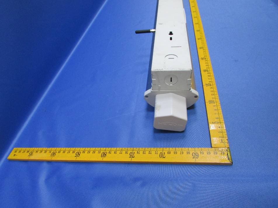
Click to zoom
Application Details
- Equipment Class
- DSC - Part 15 Security/Remote Control Transmitter
- Date of Grant
- Sep 16, 2015
- Application Purpose
- Original Equipment
- Date of Application
- Sep 16, 2015
- Equipment Note
- Artemis Ceiling Mounted LED Stairwell Fixture
- Frequency Range
- 433.10700000 - 434.83300000
- Country
- China
Documents & Files
Document Text
Text extracted from the exhibit documents filed with the FCC. Open a document above to read the original.
Users Manual
Artemis Series of Low Occupancy LED Ceiling Mounted Fixtures (Including Stairwells) Installation & Operation Guide Xeleum Lighting, LLC. 333 North Bedford Rd. Mount Kisco, NY 10549 * Phone 954‐617‐8170 * Fax 954‐571‐9777 * www.xeleum.com 1 Low Occupancy FixtureXL Stairwell Fixture XS Basic Fixture XB Please read these instructions carefully, and keep them for future reference. 2 Xeleum Lighting, LLC. 333 North Bedford Rd. Mount Kisco, NY 10549 * Phone 954‐617‐8170 * Fax 954‐571‐9777 * www.xeleum.com IMPORTANT SAFEGUARDS When using electrical equipment, basic safety precautions should always be followed including the following: a) READ AND FOLLOW ALL SAFETY INSTRUCTIONS. b) Do not use outdoors. c) Do not let power supply cords touch hot surfaces. d) Do not mount near gas or electric heaters. e) Use caution when servicing batteries. Battery acid can cause burns to skin and eyes. If acid is spilled on skin or in eyes, flush acid with fresh water and contact a physician immediately. f) Equipment should be mounted in locations and at heights where it will not readily be subjected to tampering by unauthorized personnel. g) The use of accessory equipment not recommended by the manufacturer may cause an unsafe condition. h) Do not use this equipment for other than intended use. SAVE THESE INSTRUCTIONS Artemis Series of Low Occupancy LED Ceiling Mounted Fixtures (Including Stairwells) Installation & Operation Guide PARTS & TOOLS REQUIRED: Artemis Stairwell Fixture Wire Nuts Flat Blade Screwdriver (Not Provided) WARNING: Turn power off at circuit breaker or fuse box. Do not rely on a wall switch alone to turn off power. Failure to do so may cause a shock hazard and damage this electronic fixture! 3 Drill and Masonry Drill Bits (Not provided) Phillips Screwdriver (Not Provided) Xeleum Lighting, LLC. 333 North Bedford Rd. Mount Kisco, NY 10549 * Phone 954‐617‐8170 * Fax 954‐571‐9777 * www.xeleum.com Anchors & Mounting Hardware (Not Provided) Note: Ensure compliance with local codes and ordinances. Artemis Series of Low Occupancy LED Ceiling Mounted Fixtures (Including Stairwells) Installation & Operation Guide 4 Step DescriptionImage 1 Remove the fixture from the packaging and make sure it has arrived in good condition. Place the fixture on a flat surface and remove two screws which secure the back‐box to the light engine (located on either side of the fixture in the middle and just behind the lens). 2 Use a straight slot screw driver and gently pry the sheet metal away from the light engine. There is a notch designed into the back box for this purpose. This will release the primary light engine from the back box (white). 3 Carefully remove the primary light engine and set it next to the back box. There are two connectors that must be disconnected. The larger of the two connectors is for the motion sensor array. The smaller connector powers the light engine. 4 After removing the existing fixture from the ceiling, position the new back box where you want it. Using the provided openings, secure the back box to the imbedded junction box (if power is coming in from the back of the fixture). Check the alignment of the back box and then secure the ends of the fixture using the provided holes. An anchor or Tapcon is recommended, ensuring that this is compliant with local codes and ordinances. Note: Use washers as spacers if the ceiling is not flat. Not doing so can result in a warping of the back box, making it difficult to snap in the primary light engine. 5 If installing an emergency back‐up battery, us a Philips screwdriver to remove the battery holding fixture closest to the driver. Installation Xeleum Lighting, LLC. 333 North Bedford Rd. Mount Kisco, NY 10549 * Phone 954‐617‐8170 * Fax 954‐571‐9777 * www.xeleum.com Artemis Series of Low Occupancy LED Ceiling Mounted Fixtures (Including Stairwells) Installation & Operation Guide 4 Step DescriptionImage 6 Feed the battery connector through the opening in the battery holder you just removed. Place the other end of the battery in the corresponding holder. Use a Philips head screwdriver and re‐install the battery holder. Plug the white connector coming out of the battery into the matting connector inside the back box. 7 If power is coming into the fixture via an electrical conduit (flex or rigid), use one of the knockouts at either end of the fixture. Make sure the proper strain reliefs are used to fully comply with local codes or ordinances. 8 Hook up the three incoming power wires to the three wires within the back box. Use the provided wire nuts or similar products to ensure the safety of the installation. 9 Hold the light engine close to the back box mounted to the ceiling and plug in the two connectors (sensor array and power for the light engine). 10 Snap the light engine into the back box, being very careful not to pinch any wires. You may need to pry back the metal of the back box slightly to facilitate this step. Once the light engine is snapped into the back box re‐install to the two screws into either side of the fixture. 5 Note: If a replacement battery is needed, the part number is as follows: XAP‐0039 Xeleum Lighting, LLC. 333 North Bedford Rd. Mount Kisco, NY 10549 * Phone 954‐617‐8170 * Fax 954‐571‐9777 * www.xeleum.com Artemis Series of Low Occupancy LED Ceiling Mounted Fixtures (Including Stairwells) Installation & Operation Guide Installation (cont.) Control Panel For Stairwell (XS) Fixtures Floor X1 Dial Switch: This dial is set to indicate the floor a particular fixture is being installed on. If the fixture is being installed on the 4 th floor, this dial would be set to “4”. If the fixture is being installed on the 23 rd floor this dial would be set to “3”, etc. Stairwell Dial Switch: Some buildings have more than one stairwell. This switch helps to keep fixtures in one stairwell from talking to fixtures in another stairwell. If you have one stairwell, use a small straight slot screwdriver and set the dial to “1”. For multiple stairwel…
Text truncated - open the document above for the full version.
Cover Letter(s)
RDI Technology (Shenzhen) Co., Ltd. Date: Sep. 11, 2015 Federal Communications Commission Authorization and Evaluation Division Confidentiality Request regarding application for certification of FCC ID: SJ8-XASC04 Pursuant to Sections 0.457 and 0.459 of the Commission’s Rules, we hereby request confidential treatment of information accompanying this application as outlined below: Exhibit Type File Name Schematics Block Diagram Operational Description Schematics.pdf BlockDiagram.pdf CircuitDescription.pdf The above materials contain trade secrets and proprietary information not customarily released to the public. The public disclosure of these materials may be harmful to the applicant and provide unjustified benefits to its competitors. The applicant understands that pursuant to Section 0.457 of the Rules, disclosure of this application and all accompanying documentation will not be made before the date of the Grant for this application. Sincerely, ................................................... Signature Tony. zhou / Manager ................................................... Typed name and Title RDI Technology (Shenzhen) Co., Ltd.
Cover Letter(s)
RDI Technology (Shenzhen) Co., Ltd. FCC ID: SJ8-XASC04 POWER OF ATTORNEY Date: Sep. 11, 2015 Federal Communications Commission Authorization and Evaluation Division 7435 Oakland Mills Road Columbia, MD 21046 To Whom It May Concern: We, the undersigned, hereby authorize Waltek Services (ShenZhen) Co., Ltd. (Philo Zhong) on our behalf, to apply to the Federal Communications Commission on our equipment. Any and all acts carried out by Waltek Services (ShenZhen) Co., Ltd. (Philo Zhong) on our behalf shall have the same effect as acts of our own. This authorization expires on Sep. 10, 2016. This is to advise that we are in full compliance with the Anti-Drug Abuse Act. We, RDI Technology (Shenzhen) Co., Ltd. are not subject to a denial of federal benefits pursuant to Section 5301 of the Anti-Drug Act of 1988, 21 USC853a, and no party to the application is subject to a denial of federal benefits pursuant to that section. Sincerely, ................................................................................. Signature Tony. zhou / Manager ................................................................................. Typed name and Title RDI Technology (Shenzhen) Co., Ltd.
Cover Letter(s)
Page 1 of 1 Date of Test: Test Lab Attestation Letter Sep. 08– Sep. 14, 2015 Applicant Name: RDI Technology (Shenzhen) Co., Ltd. FCC ID: SJ8-XASC04 Name of Engineer Performing Test: Silin Chen , Engineer Statement of Compliance: (Test Lab) declares that this Unit has been tested in accordance with the test method identified in this test report and that we observed it being tested. It also declares that the Unit complies with the relevant limits. All instrumentation and accessories used to test this unit for compliance to the indicated test method are calibrated regularly in accordance with ISO 17025:2005 requirements by laboratories accredited by A2LA, NVLAP, or ACLAS for the measurement parameters. The measurements were made at: Shenzhen SEM.Test Technology Co., Ltd. 1/F, Building A, Hongwei Industrial Park, Liuxian 2nd Road, Bao'an District, Shenzhen, P.R.C.(518101) Test Lab Witness‐ Signature of Test Lab Witness: Full Name, Typed: Silin Chen , Engineer Title of Witness: Engineer Email Address: [email protected] Phone No.: +86‐755‐33663308
Cover Letter(s)
RDI Technology (Shenzhen) Co., Ltd. Date:Sep.11, 2015 Subject: authorization for adding family models To whom it May concern, Statement We would like to confirm all the models XASC04, XALF04 are the same circuit and RF module. There only difference is product model name and the function as below. XALF04 is designed as a Low occupancy fixture for other than stairwell locations. These fixtures will dim all the way to off when an area is unoccupied. The XASC04 is dim down to about 7 watts in an unoccupied stairwell but do not dim all the way to off. Yours sincerely, [Signature] Name(full name): Tony Zhou Title: Manager RDI Technology (Shenzhen) Co., Ltd.
External Photos
Reference No.: WTS15S0933194E Waltek Services (Shenzhen) Co.,Ltd. http://www.w altek.com.cn 12 Photographs - Constructional Details 12.1 Model XASC04- External Photos Reference No.: WTS15S0933194E Waltek Services (Shenzhen) Co.,Ltd. http://www.w altek.com.cn Reference No.: WTS15S0933194E Waltek Services (Shenzhen) Co.,Ltd. http://www.w altek.com.cn ANT
ID Label/Location Info
FCC Label This device complies with part 15 of the FCC Rules. Operation is subject to the following two conditions: (1) This device may not cause harmful interference, and (2) this device must accept any interference received, including interference that may cause undesired operation. Proposed Label Location on EUT EUT Back View/ proposed IC Label Location RDI Technology (Shenzhen) Co., Ltd Model No. : XASC04 FCC ID: SJ8-XASC04 IC : 7644A-XASC04 RDI Technology (Shenzhen) Co., Ltd Model No. : XALF04 FCC ID: SJ8-XASC04 IC : 7644A-XASC04
ID Label/Location Info
This device complies with part 15 of the FCC Rules. Operation is subject to the following two conditions: (1) This device may not cause harmful interference, and (2) this device must accept any interference received, including interference that may cause undesired operation. FCC Label Sample for Model: XASC04 RDI Technology (Shenzhen) Co., Ltd Model No. : XASC04 FCC ID: SJ8-XASC04 IC: 7644A-XASC04 FCC Label Sample for Model: XALF04 RDI Technology (Shenzhen) Co., Ltd Model No. : XALF04 FCC ID: SJ8-XASC04 IC: 7644A-XASC04
Internal Photos
Reference No.: WTS15S0933194E Waltek Services (Shenzhen) Co.,Ltd. http://www.w altek.com.cn 12.2 Model XASC04- Internal Photos Reference No.: WTS15S0933194E Waltek Services (Shenzhen) Co.,Ltd. http://www.w altek.com.cn RF Cable Reference No.: WTS15S0933194E Waltek Services (Shenzhen) Co.,Ltd. http://www.w altek.com.cn Reference No.: WTS15S0933194E Waltek Services (Shenzhen) Co.,Ltd. http://www.w altek.com.cn
Test Report
Waltek Services (Shenzhen) Co.,Ltd. http://www.waltek.com.cn Page 1 of 29 TEST REPORT Reference No. .................... : WTS15S0933194E FCC ID ................................ : SJ8-XASC04 Applicant ............................ : RDI Technology (Shenzhen)Co., Ltd. Address .............................. : Building C1, Xintang Industrial Park East Baishixia, Fuyong, Baoan, Shenzhen, Guangdong, China Manufacturer .................... : The same as above Address .............................. : The same as above Product Name .................... : Artemis Ceiling Mounted LED Stairwell Fixture/ Artemis Ceiling Mounted LED Low Occupancy Fixture Model No. ........................... : XASC04, XALF04 Standards........................... : FCC CFR47 Part 15 Section 15.231: 2014 Date of Receipt sample .... : Sep. 08, 2015 Date of Test ....................... : Sep. 08 – Sep.14, 2015 Date of Issue ...................... : Sep. 16, 2015 Test Result ......................... : Pass Remarks: The results shown in this test report refer only to the sample(s) tested, this test report cannot be reproduced, except in full, without prior written permission of the company. The report would be invalid without specific stamp of test institute and the signatures of compiler and approver. Prepared By: Waltek Services (Shenzhen) Co., Ltd. Address: 1/F., Fukangtai Building, West Baima Road, Songgang Street, Baoan District, Shenzhen, Guangdong, China Tel :+86-755-83551033 Fax:+86-755-83552400 Compiled by: Approved by: Zero Zhou / Project Engineer Philo Zhong / Manager Reference No.: WTS15S0933194E Page 2 of 29 Waltek Services (Shenzhen) Co.,Ltd. http://www.waltek.com.cn Page 2 of 29 2 Test Summary Test Items Test Requirement Result Conducted Emissions 15.207 PASS Radiated Spurious Emissions 15.205(a) 15.209 15.231(a) PASS Periodic Operation 15.231(a) PASS Emission Bandwidth 15.231(c) PASS Antenna Requirement 15.203 PASS Reference No.: WTS15S0933194E Page 3 of 29 Waltek Services (Shenzhen) Co.,Ltd. http://www.waltek.com.cn 3 Contents Page 1 COVER PAGE ...................................................................................................................................... 1 2 TEST SUMMARY ............................................................................................................................................. 2 3 CONTENTS ....................................................................................................................................................... 3 4 GENERAL INFORMATION ............................................................................................................................. 4 4.1 GENERAL DESCRIPTION OF E.U.T. ....................................................................................................... 4 4.2 DETAILS OF E.U.T. ................................................................................................................................ 4 4.3 TEST MODE ........................................................................................................................................... 4 4.4 TEST FACILITY ....................................................................................................................................... 4 5 EQUIPMENT USED DURING TEST ............................................................................................................. 5 5.1 EQUIPMENTS LIST ................................................................................................................................. 5 5.2 MEASUREMENT UNCERTAINTY .............................................................................................................. 5 5.3 TEST EQUIPMENT CALIBRATION ........................................................................................................... 5 6 CONDUCTED EMISSION ............................................................................................................................... 6 6.1 E.U.T. OPERATION ............................................................................................................................... 6 6.2 EUT SETUP ........................................................................................................................................... 6 6.3 MEASUREMENT DESCRIPTION .............................................................................................................. 6 6.4 CONDUCTED EMISSION TEST RESULT .................................................................................................. 7 7 RADIATED SPURIOUS EMISSIONS ............................................................................................................ 9 7.1 EUT OPERATION ................................................................................................................................... 9 7.2 TEST SETUP ........................................................................................................................................ 10 7.3 SPECTRUM ANALYZER SETUP ............................................................................................................ 11 7.4 TEST PROCEDURE ............................................................................................................................... 12 7.5 SUMMARY OF TEST RESULTS ............................................................................................................. 13 8 PERIODIC OPERATION ............................................................................................................................... 15 9 EMISSION BANDWIDTH .............................................................................................................................. 18 9.1 TEST PROCEDURE ............................................................................................................................... 18 9.2 TEST RESULT .................................................................…
Text truncated - open the document above for the full version.
Test Setup Photos
Waltek Services (Shenzhen) Co.,Ltd. http://www.waltek.com.cn 11 Photographs – Model XASC04Test Setup 11.1 Photograph – Conducted Emission Test Setup 11.2 Photograph – Radiation Spurious Emission Test Setup Below 30MHz Waltek Services (Shenzhen) Co.,Ltd. http://www.waltek.com.cn 30MHz-1GHz Above 1GHz 1.5m above the ground
Contact Information
Applicant
Yuan Mike(Vice General Manager)
Test Firm
Shenzhen SEM.Test Technology Co., Ltd.Jandy So
Technical Specifications
| # | Rule Parts | Frequency Range | Power Output |
|---|---|---|---|
| 1 | 15.231 | 433.107 MHz - 434.833 MHz | - |
Other Applications from RDI Technology (Shenzhen) Co., Ltd.
SJ8-VC160
Jan 08, 2026Wireless Camera
Equipment Class
NII - Unlicensed National Information Infrastructure TXSJ8-M125
Jan 07, 2026Wireless Monitor
Equipment Class
NII - Unlicensed National Information Infrastructure TXSJ8-VC46
Dec 10, 2025Wireless Camera
Equipment Class
DTS - Digital Transmission System
SJ8-M124EI
Aug 08, 2024Wireless Monitor
Equipment Class
DTS - Digital Transmission System
SJ8M514
Dec 14, 2023Wireless 5 LCD Monitor
Equipment Class
DTS - Digital Transmission System