SJ8CA200LPORTABLE COLOR DIGITAL WIRELESS CAMERA AND MONITOR
RDI Technology (Shenzhen) Co., Ltd.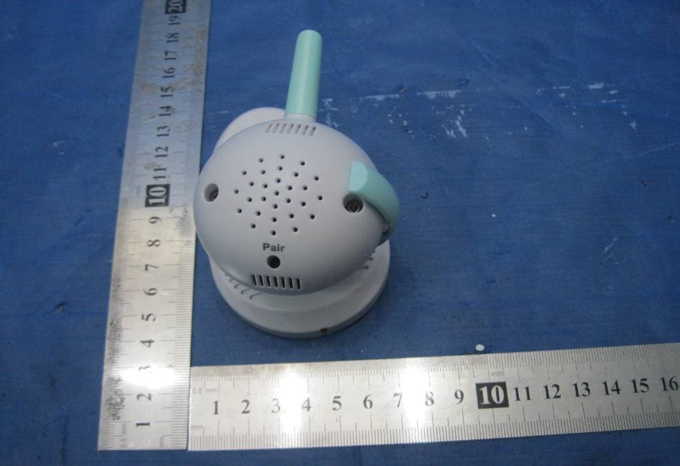
Click to zoom
Application Details
- Equipment Class
- DSS - Part 15 Spread Spectrum Transmitter
- Date of Grant
- Jan 26, 2010
- Application Purpose
- Original Equipment
- Date of Application
- Jan 26, 2010
- Equipment Note
- PORTABLE COLOR DIGITAL WIRELESS CAMERA AND MONITOR
- Frequency Range
- 2405.00000000 - 2470.00000000
- Country
- China
Documents & Files
Document Text
Text extracted from the exhibit documents filed with the FCC. Open a document above to read the original.
Users Manual
- 1 - Features ·Digital Wireless Technology Provides Excellent Image Quality and Clarity ·Interference Free, secure and private signal. ·Up to 300ft Wireless Transmission Range* ·Listen in with Exceptional Sound Clarity ·Two-way Audio *Maximum open space transmission range. The actual range is dependent upon building materials and other obstructions in path of wireless signal. Receiver Features ·2.4’’Color LCD Monitor /Receiver with Superior Image Quality ·Rechargeable Lithium Polymer Battery for True Portability ·Sound trigger alarm ·Low Power indicator Camera Features ·Night Vision allows for low light viewing up to 15 Feet/4.5meters** ·Built-in Microphone ·Camera can be battery operated for true portable wireless operation*** ·Built-in speaker to hear from monitor **IR illumination range of 15ft./4.5m under ideal conditions. Objects at or beyond this range may be partially or completely obscured, depending on the camera application. ***The rechargeable battery pack is optional at extra cost. The Digital Wireless signal transmission type used in this digital unit is also known as FHSS-Frequency Hopping Spread Spectrum. This type of signal is highly resistant to deliberate jamming as it generates a channel hopping sequence using an algorithm generated by the receiver system. Getting Started The system comes with the following components: 1x Wireless Receiver 1x Receiver Cradle 1x Wireless Camera 1x Power Adapter for Receiver 1x Power Adapter for Camera Check your package to confirm that you have received the complete system, including all components shown above. - 2 - Wireless Receiver Front Controls 1. Receiver Antenna-Receives & Sends signals from or to the Camera. 2. Power /Low Power Indicator-The left Green LED indicates the Receiver Power is ON or OFF. The Red LED’s flash to indicate the power is low. 3. LCD Screen-Displays video from the Camera. 4. P/S Button-When the P/S button is pressed, the LCD Screen is turned off. The P/S feature can be used for the following two reasons: (1) To prevent the user from being disturbed (i.e. when sleeping) by the bright LCD screen, or (2) To conserve battery power. If audio is detected above the preset audio trigger level on the Camera, the Receiver will beep and display the Camera. The receiver will return to P/S mode about 5 seconds after the Alarm has completed. Press P/S while the screen is off, or press any other key in the front panel while the screen is on will cancel this mode. 5. Navigation Controls-Use the controls in Viewing Mode. Viewing Mode: The following controls are used while watching live video from the camera: Press the UP/DOWN buttons to Increase or Decrease the volume. Press the LEFT/RIGHT butters to decrease or increase the EV. 6. Ta l k-Press and hold the button in Viewing Mode to talk with the baby. 7. Microphone-Receives sounds for the area near the receiver, and transmits the sound from the receiver to the camera. 8. Speaker-Produces the sound transmitted from the Camera. 9. Stand-Flip the stand out to place the receiver on a flat surface (such as a table or countertop). Alternatively, place the receiver in the Receiver Cradle. Bottom Control 10. Pair Button-Press the Pair button when pairing the Receiver with a Camera. - 3 - Side Controls 11. Alarm +/-Button-Press to increase or decrease the volume of the audio alarm. 12. Power Button-Slide to turn the Receiver ON or OFF. 13. DC 5V Power Input-Connect the included DC5V Power Adapter to power the receiver and/or charge the Receiver battery (When the receiver is not in the Cradle). Receiver Cradle Inputs 14. DC 5V Power Input –Connect the DC 5V Power Adapter (included) to the Receiver Cradle to power the receiver and/or charge the Receiver (when docked). Wireless Receiver Installation Determine if you will be using the Receiver Cradle, or connecting the cables directly to the receiver before installation: 1. Place the Receiver Cradle or Receiver in a place that will have clear reception with your camera. 2. Plug the AC adapter power output cable into the 5V POWER input of the Cradle or Receiver. Plug the power plug into a wall outlet or surge protector. 3. Leave the receiver to charge for 6hours prior to first time use so the built-in rechargeable receiver battery is fully charged. DO NOT remove the power cable from the receiver / from the cradle during initial charging process .After initial charge, charge as required. Camera Front & Back 1. Camera Antenna-Receives & Sends signals to or from the Receiver. 2. Lens/IR LED-Infrared LEDs provide viewing in no/low light conditions. - 4 - 3. Microphone-Receives sounds for the area near the camera, and transmits sound from the Camera to the Receiver. 4. Speaker-Produces the sound transmitted from the receiver. 5. PAIR Button-The pairing button is located on the back of the camera behind the stand mount 6. DC 9V Power-Connect the DC 9V Power Adaptor to the Camera. NOTE: The camera can also be powered by the optional rechargeable battery pack. If the camera is plugged in with the AC adapter, the battery pack will not be used. the battery pack is intended for short term, potable camera use. Camera Installation Before you install the camera, carefully plan where and how it will be positioned, and where you will route the cable that connects the camera to the power adaptor. Before starting permanent installation, verify its performance by observing the image on the receiver when camera is positioned in the same location/position where it will be permanently installed and the receiver is places in the location where it will be used most of the time. Installation Warnings Aim the Camera to best optimize the viewing area: Select a location for the camera that provides a clear view of the area you want to monitor, which is free from dust, and is not in line-of-sight to a strong light source or direct sunlight. Avoid installing the camera where there are thick walls, or obstructions between the Camera and the Receiver. Night Vision Thi…
Text truncated - open the document above for the full version.
Cover Letter(s)
RDI Technology (Shenzhen) Co., Ltd FCC ID: SJ8CA200L POWER OF ATTORNEY Jan 25,2010 Federal Communications Commission Authorization and Evaluation Division 7435 Oakland Mills Road Columbia, MD 21046 To Whom It May Concern: We, the undersigned, hereby authorize Waltek Services (ShenZhen) Co., Ltd. (Philo Zhong) on our behalf, to apply to the Federal Communications Commission on our equipment. Any and all acts carried out by Waltek Services (ShenZhen) Co., Ltd. (Philo Zhong) on our behalf shall have the same effect as acts of our own. This authorization expires on Jan 26, 2011. This is to advise that we are in full compliance with the Anti-Drug Abuse Act. We, RDI Technology (Shenzhen) Co., Ltd., are not subject to a denial of federal benefits pursuant to Section 5301 of the Anti-Drug Act of 1988, 21 USC853a, and no party to the application is subject to a denial of federal benefits pursuant to that section. Sincerely, RDI Technology (Shenzhen) Co., Ltd ------------------------------- Engineering Manager
External Photos
2.1 EUT - Front View 2.2 EUT - Back View
ID Label/Location Info
RDI Technology (Shenzhen) Co., Ltd FCC ID: SJ8CA200L Page 46 of 46 16 FCC ID Label This device complies with Part 15 of the FCC Rules. Operation is subject to the following two conditions:(1)this device may not cause harmful interference,and (2) this device must accept any interference received, including interference that may cause undesired operation. The Label must not be a stick-on paper. The Label on these products must be permanently affixed to the product and readily visible at the time of purchase and must last the expected lifetime of the equipment not be readily detachable. Proposed Label Location on EUT EUT Bottom View/proposed FCC Mark Location FCC ID:SJ8CA200L This device complies with Part 15 of the FCC Rules. Operation is subject to the following two conditions: (1) this device may not cause harmful interference, and (2) this device must accept any interference received, including interference that may cause undesired operation
ID Label/Location Info
FCC ID Label Sample for Model CMD2027 FCC ID : SJ8CA200L This device complies with Part 15 of the FCC Rules. Operation is subject to the following two conditions:(1)this device may not cause harmful interference, and (2) this device must accept any interference received, including interference that may cause undesired operation.
Internal Photos
2.1 PCB1 - Front View 2.2 PCB1 - Back View 2.3 PCB2 - Front View 2.4 PCB2 - Back View 2.5 PCB3 - Front View 2.6 PCB3 - Back View
Operational Description
Circuit Description The unit is base on a single-chip COMS camera sensor (OV7725) provide a high quality video, built-in an audio microphone, auto turn on/off IR LED for night vision and audio alert when audio volume over preset level. Microprocesser (SN93131) runs at 12MHz, code and decode the video and audio signal and send the digital signal to MV-400 for transmitting RF radio. MV-400 runs at 12.288MHz, and it is a single chip radio transceiver for the world wide 2.4 -2.48 GHz ISM band. The transceiver consists of a fully integrated frequency synthesizer, a power amplifier, a crystal oscillator, a demodulator. Output power, frequency channels, and protocol setup are easily programmable through a SPI interface. Current consumption is very low. Built-in Power Down and Standby modes makes power saving easily realizable.
Test Report
RDI Technology (Shenzhen) Co., Ltd FCC ID: SJ8CA200L FCC TEST REPORT Page 1 of 46 FCC ID : SJ8CA200L Applicant : RDI Technology (Shenzhen) Co., Ltd Address of Applicant : Building C1 Xingtang Industrial Park,East Baishixia, Fuyong,Baoan, Shenzhen,PRC. Equipment Under Test (EUT) : Product description : Portable Color Digital Wireless Camera And Monitor Model No. : CMD2027 Frequency Range : 2405~2470MHz Standards : FCC 15 Paragraph 15.247 Date of Test : Jan.25,2010 Test Engineer : Olic huang Reviewed By : PERPARED BY: Waltek Services (Shenzhen) Co., Ltd. 1/F, Fukangtai Building,West Baima Rd.,Songgang Street, Baoan District, Shenzhen 518105,China Tel :+86-755-27553488 Fax:+86-755-27553868 RDI Technology (Shenzhen) Co., Ltd FCC ID: SJ8CA200L Page 2 of 46 2 Contents Page 1 COVER PAGE..........................................................................................................................................................1 2 CONTENTS ..............................................................................................................................................................2 3 TEST SUMMARY....................................................................................................................................................4 4 GENERAL INFORMATION..................................................................................................................................5 4.1 CLIENT INFORMATION............................................................................................................................................5 4.2 GENERAL DESCRIPTION OF E.U.T...........................................................................................................................5 4.3 DETAILS OF E.U.T. .................................................................................................................................................5 4.4 DESCRIPTION OF SUPPORT UNITS...........................................................................................................................5 4.5 STANDARDS APPLICABLE FOR TESTING..................................................................................................................5 4.6 TEST FACILITY........................................................................................................................................................6 4.7 TEST LOCATION......................................................................................................................................................6 4.8 EQUIPMENT USED DURING TEST.............................................................................................................................7 5 CONDUCTED EMISSION TEST ........................................................................................................................10 5.1 TEST EQUIPMENT..................................................................................................................................................10 5.2 TEST PROCEDURE.................................................................................................................................................10 5.3 CONDUCTED TEST SETUP.....................................................................................................................................11 5.4 EUT OPERATING CONDITION...............................................................................................................................11 5.5 CONDUCTED EMISSION LIMITS.............................................................................................................................12 5.6 CONDUCTED EMISSION TEST DATA......................................................................................................................12 5.7 CONDUCTED EMISSION TEST SETUP VIEW............................................................................................................14 6 RADIATION EMISSION TEST...........................................................................................................................15 6.1 TEST EQUIPMENT..................................................................................................................................................15 6.2 MEASUREMENT UNCERTAINTY.............................................................................................................................15 6.3 TEST PROCEDURE.................................................................................................................................................15 6.4 RADIATED TEST SETUP.........................................................................................................................................16 6.5 SPECTRUM ANALYZER SETUP...............................................................................................................................16 6.6 CORRECTED AMPLITUDE & MARGIN CALCULATION............................................................................................17 6.7 SUMMARY OF TEST RESULTS................................................................................................................................17 6.8 EUT OPERATING CONDITION...............................................................................................................................18 6.9 RADIATED EMISSIONS LIMIT ON PARAGRAPH 15.209 ...........................................................................................18 6.10 RADIATED EMISSIONS TEST RESULT................................................................................................................19 6.11 RADIATED EMISSION DATA.............................................................................................................................19 7 MAXIMUM PEAK OUTPUT POWER...............................................................................................................24 8 HOPPING …
Text truncated - open the document above for the full version.
Test Setup Photos
Photographs of Testing Radiation Emission Test View For 30MHz-1000MHz Radiation Emission Test View For 1GHz-25GHz Conducted Emission Test Setup View
Contact Information
Applicant
Yuan Mike(Vice General Manager)
Test Firm
Waltek Services(Shenzhen) Co., Ltd.Philo zhong
Technical Specifications
| # | Rule Parts | Frequency Range | Power Output |
|---|---|---|---|
| 1 | 15C | 2.40 GHz - 2.47 GHz | 12.00 mW |
Other Applications from RDI Technology (Shenzhen) Co., Ltd.
SJ8-VC160
Jan 08, 2026Wireless Camera
Equipment Class
NII - Unlicensed National Information Infrastructure TXSJ8-M125
Jan 07, 2026Wireless Monitor
Equipment Class
NII - Unlicensed National Information Infrastructure TXSJ8-VC46
Dec 10, 2025Wireless Camera
Equipment Class
DTS - Digital Transmission System
SJ8-M124EI
Aug 08, 2024Wireless Monitor
Equipment Class
DTS - Digital Transmission System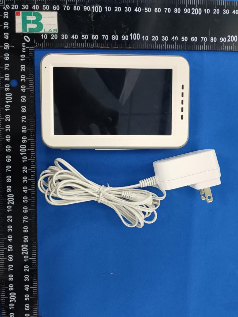
SJ8M514
Dec 14, 2023Wireless 5 LCD Monitor
Equipment Class
DTS - Digital Transmission System