SJ8CA300WIRELESS CAMERA
RDI Technology (Shenzhen) Co., Ltd.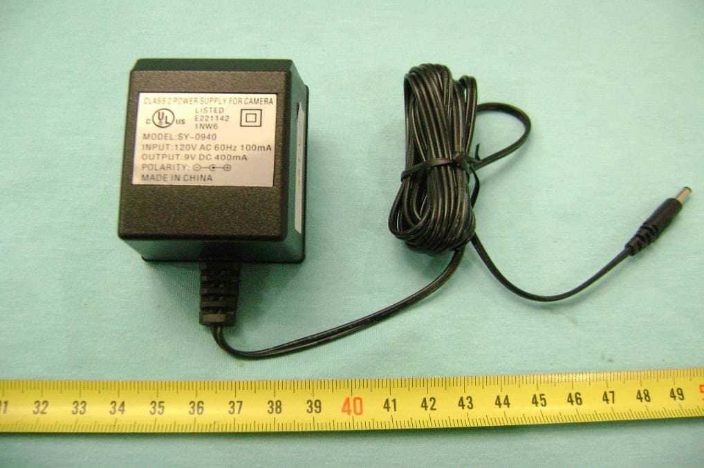
Click to zoom
Application Details
- Equipment Class
- DXX - Part 15 Low Power Communication Device Transmitter
- Date of Grant
- Mar 19, 2008
- Application Purpose
- Original Equipment
- Date of Application
- Mar 19, 2008
- Equipment Note
- WIRELESS CAMERA
- Frequency Range
- 910.00000000 - 920.00000000
- Country
- China
Documents & Files
Document Text
Text extracted from the exhibit documents filed with the FCC. Open a document above to read the original.
Users Manual
7 Drilling Template for Wall Mounting Camera(s)/// For wall-mounting Camera (s), drill three holes using a 1/4” drill bit and the template below. Insert supplied wall anchors into holes and secure Camera to wall with supplied screws. INDOOR/OUTDOOR 900MHz WIRELESS CAMERA SYSTEM USINCLUDES: VIDEO/AUDIO CAMERA TRANSMITTER & MONITOR/RECEIVER CR3020 USER’S GUIDE Congratulations on your purchase of the 900MHz Wireless Color Camera system . The system consists of a wireless A/V receiver and a wireless Camera, an ideal product for application of covert monitoring, such as the porch, watching the yard, pool, pets or the baby. It is also suited to small business surveillance application. . FEATURES • 900MHz wireless technology • Color camera with night vision • Both audio and video output • Supports up to 2 cameras • Manual or auto switching between cameras • Adjustable cycle time between different channels • AC power adaptor or battery operation • Weatherproof construction( IP54 standard) for outdoor use • WiFi interference free SYSTEM CONTENTS • Wireless A/V receiver x1 • Wireless Camera with night vision x1 •Power adaptor x2 •Adaptor cable x1 •Hardware kit x1 •Manual x1 THINGS TO CONSIDER BEFORE INSTALLATION For best performance, follow these simple guidelines: • Camera(s) should be installed between 8 and 13 feet above the area to be APPROVALS/// This device complies with part 15 of the FCC rules. Operation is subject to the following two conditions: (1) this device may not cause harmful interference, and (2) this device must accept any interference received, including interference that may cause undesired operation. FCC NOTE: The manufacturer is not responsible for any radio or TV interference caused by unauthorized modifications to this equipment. Such modifications could void the user's authority to operate the equipment. WARRANTY/// This product has a one year manufacturer’s warranty which covers parts and labor only. In the Unlikely event that you encounter a problem, the unit should be returned to the place of purchase. 1 6 5 Interference on camera picture 1. Make sure each camera (transmitter) is within range, and that no large obstructions are blocking the signal. 2. Try repositioning the camera, receiver or both to improve the reception quality. 3. If a camera is positioned close to the receiver, point antenna away from the receiver. Audio problems 1. Ensure the volume is turned up sufficiently on the TV. 2. Make sure the sound is within the microphone range. 3. If the unit emits a loud wailing sound (feeds back), try moving the camera away from the receiver or angle the receiver differently. SPECIFICATIONS Camera TV System PAL or NTSC Resolution 360 horizontal TV Lines Signal/Noise Ratio 48dB High-Speed Electronic Shutter 1/60 - 1/15,000 sec Image Sensor 1/3” CMOS Min. Illumination 0.1 lux Current Consumption 150mA Overall Size 2.36"L×1.69" Diameter Frequency 910MHz, 920MHz Modulation FM Video Signal/Noise Ratio 48dB Audio Signal/Noise Ratio 45dB Case Finish Metal Aluminum case, suited for indoor or outdoor use 2 monitored • The Camera should be aimed accordingly to optimize viewing area • For best transmission, avoid installations where there are thick walls or major obstructions between the Camera and Receiver INSTALLING THE CAMERA (TRANSMITTER) 1. Unpack the Camera. 2. Decide whether the Camera will be wall-mounted or sit on a desk/table top. If wall mounting, use the hardware kit in the package. The Camera can be adjusted for either mounting scenario by rotating the Camera to the required position. DESK TOP WALL MOUNTING 3. If using the 9V camera power adapter, just connect power jack. Make sure the Camera is positioned no more than 5 1/2 feet from an AC power outlet. 4. Each camera’s channel number can be set by user, screw the lens part of camera to open the lens cover, and then could set the camera’s channel number. After finish setting the channel, screw the lens cover on. 5. The Camera (Transmitter) installation is now complete. Night Vision/// The Camera includes IR LEDs, which allows viewing up to 12 feet in the dark when used with the adapter. It can automatically turn to night vision in low light. SETTING UP THE RECEIVER 3 1. Connect one end of the cable to the back of the receiver, the another end (RCA cord) to your television's A/V inputs, the yellow plug to the VIDEO IN jack and the white plug to the AUDIO IN jack. 2. Plug the receiver power adapter into the 9V DC power jack on the back of the receiver and plug the power adapter into any 120 V/240 V power outlet. 3. Place the receiver either on top or near to your TV. Rotate the antenna to a vertical position. OPTIMIZING THE WIRELESS CAMERA SYSTEM The 900MHz video signals pass easily through your home’s interior walls, but the signal may be reflected by power wires or plumbing inside the wall. Usually a slight adjustment of the Receiver and/or Camera antenna will improve reception. Take care not to force the antennas past their lock positions. MULTI-CAMERA OPERATION Our wireless 900MHz Camera system is designed to work with up to 2 Cameras. Additional Cameras are sold separately. IMPORTANT: When using more than one Camera, please check channel number on package, make sure it is exclusive to each camera. Accordingly the dip switch located on the back of the Receiver should be adjusted to reflect the channels in use. OPERATING THE SYSTEM Set your TV to monitor the VIDEO INPUT designated for the Receiver. The receiver can support up to two different camera/transmitter signals. You can switch from one camera to the next either manually or automatically via button on the top panel of the receiver. MANUAL MODE To select one of the two channels manually, press the MANUAL button on the panel of the receiver. The receiver will switch to a different channel (CAM1, CAM2) each time when the MANUAL button is pressed. To avoid searching channels that do not have 4 cameras/transmitters assigned to them, set the DIP switches (locate…
Text truncated - open the document above for the full version.
Cover Letter(s)
安帝爱科技(深圳)有限公司 RDI Technology (Shenzhen) Co., Ltd. FCC ID: SJ8CA300 POWER OF ATTORNEY Mar.5, 2008 Federal Communications Commission Authorization and Evaluation Division 7435 Oakland Mills Road Columbia, MD 21046 To Whom It May Concern: We, the undersigned, hereby authorize Waltek Services (Hongkong) Co., Ltd. (Philo Zhong) on our behalf, to apply to the Federal Communications Commission on our equipment. Any and all acts carried out by Waltek Services (Hongkong) Co., Ltd. (Philo Zhong) on our behalf shall have the same effect as acts of our own. This authorization expires on Mar.6, 2009. This is to advise that we are in full compliance with the Anti-Drug Abuse Act. We, RDI Technology (Shenzhen) Co., Ltd., are not subject to a denial of federal benefits pursuant to Section 5301 of the Anti-Drug Act of 1988, 21 USC853a, and no party to the application is subject to a denial of federal benefits pursuant to that section. Sincerely, RDI Technology (Shenzhen) Co., Ltd. ------------------------------- Jack Sheng Engineering Manager
External Photos
EUT - Front View EUT - Back View Adapter - Front View Adapter - Back View
ID Label/Location Info
FCC ID Label Sample for Model: CA300 FCC ID: SJ8CA300
ID Label/Location Info
FCC ID Label This device complies with Part 15 of the FCC Rules. Operation is subject to the following two conditions: (1) this device may not cause harmful interference, and (2) this device must accept any interference received, including interference that may cause undesired operation The Label must not be a stick-on paper. The Label on these products must be permanently affixed to the product and readily visible at the time of purchase and must last the expected lifetime of the equipment not be readily detachable. Proposed Label Location on EUT EUT Bottom View/proposed FCC Mark Location FCC ID: SJ8CA300
Internal Photos
PCB1 - Front View 2.1 PCB1 - Back View PCB2 - Front View PCB2 - Back View PCB3 - Front View PCB3 - Back View
Operational Description
CA300 Wireless Camera Feb, 18th, 2008 Architecture CA300 Wireless camera includes high quality video and audio components. When combined with a RDI Wireless Video Monitor/Receiver, you have an ideal combination for watching the baby, monitoring the porch, pets, yard or the pool. It is also suite to many small business applications. CA300 wireless camera hardware architecture is show in Block diagram 1> The camera is base on a single-chip COMS camera sensor (OV7910) provide a high quality video, built-in an audio microphone, auto turn on/off IR LED for night vision and audio alert when audio volume over preset level. 2> The 900MHz TX module is assigned to transmit the video and audio signal. 3> MCU (Micro control unit) operates periodically. Including scan the switch to select the RF module channel and audio detected control
Test Report
FCC TEST REPORT Page 1 of 32 FCC ID : SJ8CA300 Applicant : RDI Technology (Shenzhen) Co., Ltd. Building C1 Xingtang Industrial Park, East Baishixia, Fuyong, Baoan, Shenzhen, P.R.C. Equipment Under Test (EUT) : Product description : Wireless Camera Model No. : CA300 Standards : FCC 15 Paragraph 15.249 Date of Test : Mar. 3, 2008 Test Engineer : Tiger Su Reviewed By : PERPARED BY: Waltek Services (Shenzhen) Co., Ltd. 8C,West Tower, Aidi Building, No.5003 Binhe Rd, Futian District, Shenzhen518045, Guangdong, China. Tel: 86-755-83551033 Fax: 86-755-83552400 RDI Technology (Shenzhen) Co., Ltd. FCC ID: SJ8CA300 Page 2 of 32 2 Contents Page 1 COVER PAGE..........................................................................................................................................................1 2 CONTENTS ...............................................................................................................................................................2 3 TEST SUMMARY .....................................................................................................................................................4 4 GENERAL INFORMATION ...................................................................................................................................5 4.1 CLIENT INFORMATION..........................................................................................................................................5 4.2 GENERAL DESCRIPTION OF E.U.T. .......................................................................................................................5 4.3 DETAILS OF E.U.T................................................................................................................................................5 4.4 DESCRIPTION OF SUPPORT UNITS.........................................................................................................................5 4.5 STANDARDS APPLICABLE FOR TESTING...............................................................................................................5 4.6 TEST FACILITY.....................................................................................................................................................6 4.7 TEST LOCATION...................................................................................................................................................6 5 EQUIPMENT USED DURING TEST .....................................................................................................................7 6 CONDUCTED EMISSION TEST............................................................................................................................8 6.1 TEST EQUIPMENT.................................................................................................................................................8 6.2 TEST PROCEDURE.................................................................................................................................................8 6.3 CONDUCTED TEST SETUP.....................................................................................................................................9 6.4 EUT OPERATING CONDITION...............................................................................................................................9 6.5 CONDUCTED EMISSION LIMITS...........................................................................................................................10 6.6 CONDUCTED EMISSION TEST RESULT................................................................................................................11 6.7 MEASUREMENT DATA........................................................................................................................................12 7 RADIATION EMISSION TEST ............................................................................................................................13 7.1 TEST EQUIPMENT...............................................................................................................................................13 7.2 MEASUREMENT UNCERTAINTY..........................................................................................................................13 7.3 TEST PROCEDURE...............................................................................................................................................13 7.4 RADIATED TEST SETUP......................................................................................................................................14 7.5 SPECTRUM ANALYZER SETUP............................................................................................................................14 7.6 CORRECTED AMPLITUDE & MARGIN CALCULATION..........................................................................................15 7.7 SUMMARY OF TEST RESULTS.............................................................................................................................15 7.8 EUT OPERATING CONDITION.............................................................................................................................16 7.9 RADIATED EMISSIONS LIMIT..............................................................................................................................16 7.10 RADIATED EMISSIONS TEST RESULT..................................................................................................................17 8 BAND EDGE............................................................................................................................................................22 8.1 TEST EQUIPMENT...............................................................................................................................................22 8.2 TEST PROCEDURE..................................................................................................................…
Text truncated - open the document above for the full version.
Test Setup Photos
Conducted Emission Test View Radiation Emission Test View For 30MHz-1000MHz Radiation Emission Test View For 1GHz-10GHz
Contact Information
Applicant
Yuan Mike(Vice General Manager)
Test Firm
Solid Industrial Co., Ltd.Yang Dengfang
Technical Specifications
| # | Rule Parts | Frequency Range | Power Output |
|---|---|---|---|
| 1 | 15C | 910 MHz - 920 MHz | - |
Other Applications from RDI Technology (Shenzhen) Co., Ltd.
SJ8-VC160
Jan 08, 2026Wireless Camera
Equipment Class
NII - Unlicensed National Information Infrastructure TXSJ8-M125
Jan 07, 2026Wireless Monitor
Equipment Class
NII - Unlicensed National Information Infrastructure TXSJ8-VC46
Dec 10, 2025Wireless Camera
Equipment Class
DTS - Digital Transmission System
SJ8-M124EI
Aug 08, 2024Wireless Monitor
Equipment Class
DTS - Digital Transmission System
SJ8M514
Dec 14, 2023Wireless 5 LCD Monitor
Equipment Class
DTS - Digital Transmission System