SJ8LSP-R1000HOME VIEWER
RDI Technology (Shenzhen) Co., Ltd.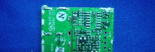
Click to zoom
Application Details
- Equipment Class
- DXX - Part 15 Low Power Communication Device Transmitter
- Date of Grant
- Sep 11, 2006
- Application Purpose
- Original Equipment
- Date of Application
- Sep 11, 2006
- Equipment Note
- HOME VIEWER
- Frequency Range
- 2410.00000000 - 2470.00000000
- Country
- China
Documents & Files
Document Text
Text extracted from the exhibit documents filed with the FCC. Open a document above to read the original.
Users Manual
IntroductionThe LSP-R1000/LSP-R1100 is a combined wireless color camera &video monitor (receiver). A high-resolution color video camera, it includesa built-in motion detector and an audio microphone. An ideal combina-tion for watching the baby, monitoring the porch, pets, yard or the pool. Itis also suited to many small business applications.Features•2 .4 GHz wireless technology • 2.5-inch (LSP-R1000) / 1.8-inch (LSP-R1100) LCD display for goodpicture display. • Plug and play installation • Supports up to 3 cameras. • LCD display can work with 3 modes : Power save, Auto and Manual • Adjustable cycle time between cameras in Auto mode. • The Brightness, Colour, Contrast, Alarm volum and Audio volume canbe adjusted. • PIR sensor function.(LSP-R1000 : Motion sensing, LSP-R1100 : Sound trigger). Package ContentsY our package contains the following: Part Name and FunctionsLCD Monitor Overview a LCD monitor screen.Displays the live image of the selected wireless camera. b Channel indicator.lights green or red when the channel is selected.Blinks when the motion is detected. c Mode select buttons.- P/S : Select when you want to place the system in scan mode. - AUTO : Select when you want to place the system in auto mode. - MANUAL : Select when you want to place the system in manualmode. d Speaker.Y ou can listen to the sounds of the wireless camera. e Power button.Tu rn the LCD monitor On or Off. f Speaker volume adjustment buttons.Adjust the speaker volume level by using the volume buttons. g Alarm volume adjustment button.Adjust the alarm volume of the LCD monitor by tuning the alarm vol-ume tuner. h MENU button.Y ou can select the Brightness, Colour or Contrast setting mode. i v/V buttonss Adjusts the level value of the Brightness, Colour or Contrast. j Audio/Video output jack.Yo u can connect the other display and/or sound device by using supplied AV cable. k DC 9V Power input jack. l Battary case.Y ou can use the LCD monitor without the power supply adapter by using the four AA type batteries or battery pack (optional). Camera Overview a Camara lens. b IR(Infrared Rays) lamp sensor. c Motion sensor. d Microphone.The microphone is included on the camera. e An infrared lamp. f Battary terminal box.Y ou can use the camera without the power supply adapter or battery pack (Supplied for LSP-R1001 only) by using the four AA type bat-tery. g DC 9V Power input jack. Installing the wireless cameraInstalling your camera is a simple process. It can be placed on any hori-zontal surface. 1. Locate the camera on a hori- zontal surface. 2. Plug the power supply into the camera and then to awall outlet. 3. Make adjustments of the camera viewing angle by tilt-ing and panning the camerahead with your hand. 4. Press the POWER button to turn on the camera. Note : Make sure the power adapter cord is long enough to reach yourmounting location. Operating the Wireless Camera SystemMode operation • P/S mode : Press the P/S button on the LCD monitor, the system will bechanged to P/S mode. The LCD monitor screen blanks into astandby mode while the system continuously scans the activecameras. If a camera detects motion, the LCD monitor displaysthe camera picture and the beeper will sounds. Two minutesafter the last detection, the screen returns to standby mode whilethe LCD monitor resumes scanning. Press the MANUAL orAUTO button to cancel this mode. • AUTO mode : Press the AUTO button on the LCD monitor, the system will bechanged to auto mode. The system automatically rotatesthrough all cameras. When a camera detects motion, the LCDmonitor will display the picture from the camera for a few sec-onds and the beeper will sound. To avoid searching channelsthat do not have cameras/transmitters assigned, set the dipswitches for those corresponding channels to the off position.The dwell time(Time taken to switch between cameras) is presetto 4 seconds and can be adjusted between 2-30 seconds. Toadjust the dwell time, press both the AUTO and MANUAL but-tons simutaneously. Each flash of the LED increases the dwelltime by one second. • MANUAL mode : Press the MANUAL button on the LCD monitor to select a spe-cific camera. The LCD monitor will switch to a different cameraeach time the MANUAL button is pressed. When a cameradetects motion, the LCD monitor will display the picture of thecamera for a few seconds, and the beeper will sounds. To avoidsearching channels that do not have cameras assigned, set thedip switches for those corresponding channels to the OFF posi-tion. Menu Operation •Bri ghtness adjustment 1. Press the MENU button repeatedly on the LCD Monitor to select the brightness mode. If the LED in the ENTER buttonis turned green, stop pressing. 2. Adjust brightness level using the v/V buttons. • Blue colour adjustment 1. Press the MENU button repeatedly on the LCD Monitor to select the Colour mode. If the LED in the ENTER button isturned green and fast flicker, stop pressing. 2. Adjust blue colour level using the v/V buttons. • Blue colour adjustment 1. Press the MENU button repeatedly on the LCD Monitor to select the Colour mode. If the LED in the ENTER button isturned green and slow flicker, stop pressing. 2. Adjust red colour level using the v/V buttons. • Contrast adjustment 1. Press the MENU button repeatedly on the LCD Monitor to select the contrast mode. If the LED in the ENTER button isturned off, stop pressing. 2. Adjust contrast level using the v/V buttons. Note:If you press the MENU button, the LED is changed as shown below.T urned green ➔ T urned green and fast flicker ➔ T urned green and slow flicker ➔ T urned off ➔ T runed green. Motion-Sensing CamerasThe cameras are equiped with a motion sensor PIR. When a cameradetects motion, a red light flashes on the camera and an alert sounds onthe LCD monitor. Before Installation• The camera must not faces to direct sunlight or any bright light; oth-erwise, this may cause damage to the camera. •A void viewing areas where half of the area is in bright sunlight and the …
Text truncated - open the document above for the full version.
External Photos
EUT - Front View EUT - Back View Adapter - Front View Adapter - Back View
ID Label/Location Info
FCC ID Label Sample for Model: LSP-R1000 FCC ID: SJ8LSP-R1000 This device complies with Part 15 of the FCC Rules. Operation is subject to the following two conditions: (1) This device may not cause harmful interference, and (2) This device must accept any interference received, including interference that may cause undesired operation.
ID Label/Location Info
FCC ID Label This device complies with Part 15 of the FCC Rules. Operation is subject to the following two conditions: (1) this device may not cause harmful interference, and (2) this device must accept any interference received, including interference that may cause undesired operation The Label must not be a stick-on paper. The Label on these products must be permanently affixed to the product and readily visible at the time of purchase and must last the expected lifetime of the equipment not be readily detachable. Proposed Label Location on EUT EUT Bottom View/proposed FCC Mark Location FCC ID: SJ8LSP-R1000 This device complies with Part 15 of the FCC Rules. Operation
Internal Photos
PCB1 - Front View PCB1 - Back View PCB2 - Front View PCB2 - Back View PCB3 - Front View PCB3 - Back View PCB4 - Front View PCB4 - Back View
Operational Description
R1000 Wireless Camera Aug, 27th, 2006 Architecture R1000 Wireless camera includes high quality video and audio components. When combined with R1000 Receiver, you have an ideal combination for watching the baby, monitoring the porch, pets, yard or the pool. It is also suite to many small business applications. R1000 wireless camera hardware architecture is show in Figure 1. 1> The camera is base on a single-chip COMS Monochrome camera sensor (OV7910) provide a high quality video, built-in an audio microphone,IR LED for night vision and audio alert when audio detected 2> The 2.4GHz TX module is assigned to transmit the video and audio signal wirelessly. 3> MCU (Micro control unit) operates periodically. Including scan the switch to select the RF module channel and audio detected control
Test Report
FCC TEST REPORT Page 1 of 31 FCC ID : SJ8LSP-R1000 Applicant : RDI Technology (Shenzhen) Co., Ltd. Building C1 Xingtang Industrial Park,East Baishixia, Fuyong,Baoan, Shenzhen, PRC. Equipment Under Test (EUT) : Product description : Home Viewer Model No. : LSP-R1000 Standards : FCC 15 Paragraph 15.249 Date of Test : September 11, 2006 Test Engineer : Tiger Su Reviewed By : PERPARED BY: Waltek Services (Shenzhen) Co., Ltd. 8C,West Tower, Aidi Building, No.5003 Binhe Rd, Futian District, Shenzhen518045, Guangdong, China. Tel: 86-755-83551033 Fax: 86-755-83552400 RDI Technology (Shenzhen) Co., Ltd. FCC ID: SJ8LSP-R1000 Page 2 of 31 2 Contents Page 1 COVER PAGE..........................................................................................................................................................1 2 CONTENTS ...............................................................................................................................................................2 3 TEST SUMMARY .....................................................................................................................................................4 4 GENERAL INFORMATION ...................................................................................................................................5 4.1 CLIENT INFORMATION..........................................................................................................................................5 4.2 GENERAL DESCRIPTION OF E.U.T. .......................................................................................................................5 4.3 DETAILS OF E.U.T................................................................................................................................................5 4.4 DESCRIPTION OF SUPPORT UNITS.........................................................................................................................5 4.5 STANDARDS APPLICABLE FOR TESTING...............................................................................................................5 4.6 TEST FACILITY.....................................................................................................................................................6 4.7 TEST LOCATION...................................................................................................................................................6 5 EQUIPMENT USED DURING TEST .....................................................................................................................7 6 CONDUCTED EMISSION TEST............................................................................................................................8 6.1 TEST EQUIPMENT.................................................................................................................................................8 6.2 TEST PROCEDURE.................................................................................................................................................8 6.3 CONDUCTED TEST SETUP.....................................................................................................................................9 6.4 EUT OPERATING CONDITION...............................................................................................................................9 6.5 CONDUCTED EMISSION LIMITS...........................................................................................................................10 6.6 CONDUCTED EMISSION TEST RESULT................................................................................................................11 6.7 CONDUCTED EMISSIONS TEST DATA..................................................................................................................12 7 RADIATION EMISSION TEST ............................................................................................................................13 7.1 TEST EQUIPMENT...............................................................................................................................................13 7.2 MEASUREMENT UNCERTAINTY..........................................................................................................................13 7.3 TEST PROCEDURE...............................................................................................................................................13 7.4 RADIATED TEST SETUP......................................................................................................................................14 7.5 SPECTRUM ANALYZER SETUP............................................................................................................................14 7.6 CORRECTED AMPLITUDE & MARGIN CALCULATION.........................................................................................15 7.7 SUMMARY OF TEST RESULTS.............................................................................................................................15 7.8 EUT OPERATING CONDITION.............................................................................................................................16 7.9 RADIATED EMISSIONS LIMIT..............................................................................................................................16 7.10 RADIATED EMISSIONS TEST RESULT..................................................................................................................17 8 BAND EDGE............................................................................................................................................................19 8.1 TEST EQUIPMENT...............................................................................................................................................19 8.2 TEST PROCEDURE..................................................................................................................…
Text truncated - open the document above for the full version.
Test Setup Photos
Conduction Emission Test Setup Radiation Emission Test View For 30MHz-1000MHz Radiation Emission Test View For 1GHz-25GHz
Contact Information
Applicant
Yuan Mike(Vice General Manager)
Test Firm
SGS-CSTC Standards Technical Services Co.,Ltd.June Zhang
Technical Specifications
| # | Rule Parts | Frequency Range | Power Output |
|---|---|---|---|
| 1 | 15C | 2.41 GHz - 2.47 GHz | - |
Other Applications from RDI Technology (Shenzhen) Co., Ltd.
SJ8-VC160
Jan 08, 2026Wireless Camera
Equipment Class
NII - Unlicensed National Information Infrastructure TXSJ8-M125
Jan 07, 2026Wireless Monitor
Equipment Class
NII - Unlicensed National Information Infrastructure TXSJ8-VC46
Dec 10, 2025Wireless Camera
Equipment Class
DTS - Digital Transmission System
SJ8-M124EI
Aug 08, 2024Wireless Monitor
Equipment Class
DTS - Digital Transmission System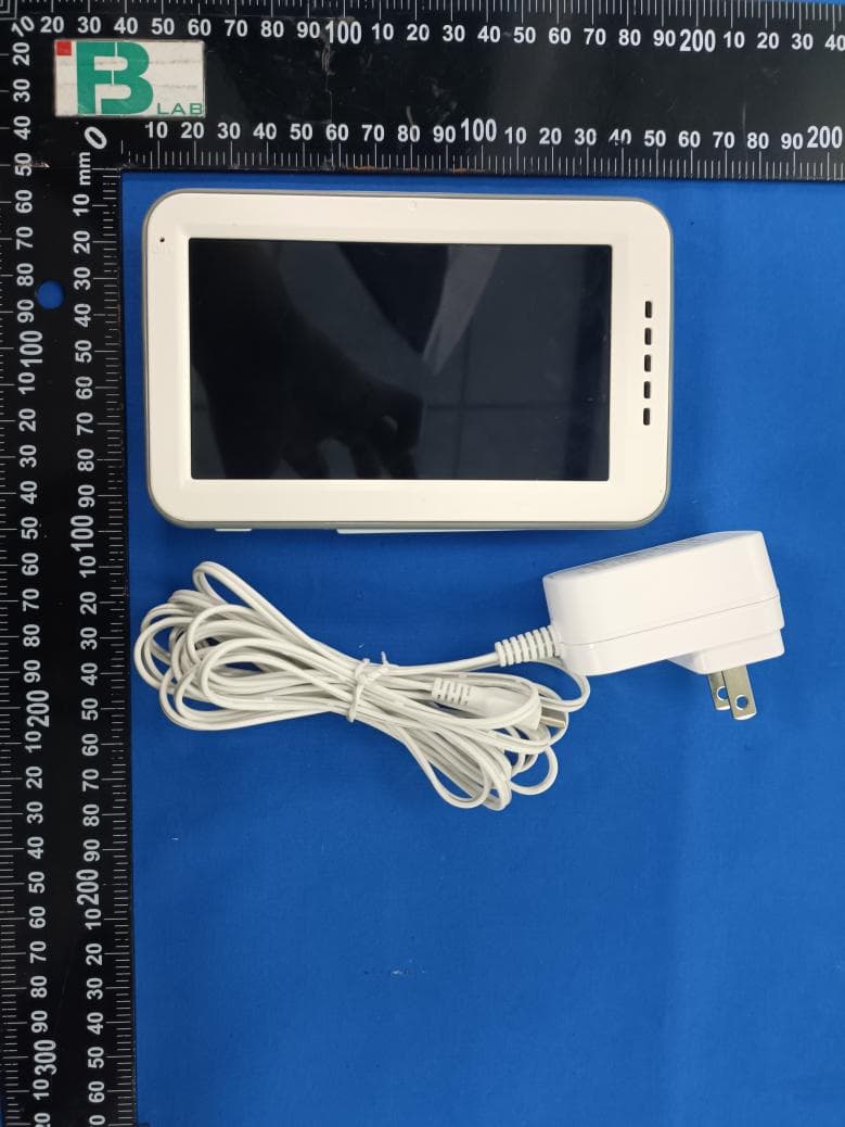
SJ8M514
Dec 14, 2023Wireless 5 LCD Monitor
Equipment Class
DTS - Digital Transmission System