SJ8M550WIRELESS CRT MONITOR
RDI Technology (Shenzhen) Co., Ltd.
Click to zoom
Application Details
- Equipment Class
- CYY - Communications Receiver used w/Pt 15 Transmitter
- Date of Grant
- Dec 16, 2007
- Application Purpose
- Original Equipment
- Date of Application
- Dec 16, 2007
- Equipment Note
- WIRELESS CRT MONITOR
- Frequency Range
- 910.00000000 - 920.00000000
- Country
- China
Documents & Files
Document Text
Text extracted from the exhibit documents filed with the FCC. Open a document above to read the original.
Users Manual
45235 BW Wireless Monitor INSTALLATION INSTRUCTIONS Congratulations on your purchase of the JASCO™ Wireless Camera system(45235 Wireless monitor) All JASCO™ Wireless Cameras includes high quality video and audio components. The 45235 BW Wireless monitor System is a combined wireless camera and video monitor/ receiver. The 45235 BW Wireless monitor surveillance system is an ideal combination for monitoring the porch, watching the yard, pool, pets or the baby. It is also suited to many small business applications. PRODUCTION FEATURES _900MHz wireless technology _Plugnplay installation _High resolution black and white video camera _Built-in microphone transmits sound from camera to TV _High quality audio and video components for long life _Supports up to 2 cameras _Auto/Manual switching between cameras and channels LED indicated _IR LED enable night vision. _AC or battery operation (batteries not included) _Sound detection and alert _Alert Volume and sound detection sensitivity are adjustable. _Has one A/V output jack _Channel lock SYSTEM Contents Please check and identify all the parts before proceeding with the installation. ❑ Wireless Camera ❑ Monitor ❑ Fixing kit ❑ 1 x 9V Camera Adapter ❑ 1 x 13.5V Monitor SETUP INSTRUCTIONS Camera Transmitter 1. Unpack the Camera/ Transmitter 2. Decide on wall or desk/table mounting the camera. If wall mounting there is a useful drilling guide on the back cover of these instructions. The camera can be adjusted for both by rotating the camera head to the required position. 3. Decide whether to connect using AC power or battery (not included). If using batteries please install appropriative LI polymer batteries. If using the power adapter, remove Battery and connect power jack. Make sure the camera is positioned no more than 51/2 feet from an AC power outlet. 4. Select the channel on the slide switch under the camera housing by switching Left or Right. Switch is preset to Channel 1. The Camera/Transmitter installation is now complete. Monitor/ Receiver 1. Unpack the Monitor/Receiver. 2. Plug the monitor power adapter into the power jack and plug the power adapter into any AC power outlet. Turn on the monitor by pressing front push button. Alternatively remove the battery compartment lid on the underside of the unit and install 10 x C type batteries (not included). 3. The Monitor/ Receiver installation is now complete. Optimizing the 45235 BW Wireless mon Video System The 900MHz video signals pass easily through your home’s interior walls, but the signal may be reflected by power wires or plumbing inside the wall. Usually a slight adjustment of the Monitor/Receiver and/or Camera/Transmitter antenna will improve reception. Take care not to force the antennas past their lock positions. Sound level can be adjusted using the volume control knob on the front of the Monitor/Receiver. Adjust Brightness/Contrast as required using controls on the rear of the Monitor/Receiver. If needed the Vertical Hold can also be adjusted at the rear. Adjust sound trigger sensitivity as required using controls on the rear of the monitor. The alert volume can also be adjusted on the rear of the monitor. The most common source of interference are microwave ovens and mobile phones. Try to avoid mounting the Monitor/Receiver near a microwave oven or other source of RF interference such as cordless phones. Sound detecting on monitor Monitor has a sound detecting function, when the sound level from cameras is great than presetting level on monitor, an audio alert will sound on the monitor. The volume control for the alert is on the rear of the monitor. Additionally a red light will flash on the front of the monitor. ADDING ADDITIONAL CAMERS You can add up to 2 additional cameras to your system. 45235-Wireless Camera Accessory (Includes Wireless Camera, Power Adapter and Fixing Kit) Channel Selection In Manual Mode individual channels may be selected. Pressing the button on the right will select Manual and theManualLED indicator will turn green. When the sound from cameras is great than monitor’s presetting level, an audio alert will sound on the channel selected. In Auto Cycle Mode the Monitor/Receiver searches between the channels available. To select Auto press the button on the left and the Auto LED indicator will turn green. When the sound from cameras is great than monitor’s presetting level, an audio alert will sound; you need to check which camera was triggered by the sound. To avoid searching empty channels, which do not have a camera connected, make sure the slide switch on the rear of the Monitor/Receiver has the corresponding switch in the correct position for each camera. Example shows a 2-camera installation. Cycle Time Setting (Time taken to switch between cameras) To alter the cycle time press both of the buttons on the front of the unit simultaneously. Each beep is one extra second of cycle time added. The cycle time can be verified by flashing LED when you release, one flash stand for one second. Cycle time can be set between 2-30 seconds. The cycle time is preset to 4 seconds. USING THE 45235 SYSTEM WITH A VCR You can connect a VCR to the 45235 System. This allows you to record the picture from your Monitor/Receiver. TROUBLE SHOOTING If you are having trouble operating this product, please consult the guide below: SYMPTOM REMEDIES No camera picture 1. Check all connectors. Make sure camera(s) and receiver are switched ON. 2. Ensure camera(s) and receiver are set to correct channel(s). 3. Make sure camera is within range of receiver. Blank monitor 1. Make sure receiver is switched ON. 2. If using AC adapter, make sure it is plugged in. 3. If using batteries, make sure they are installed correctly, or try recharging(replacing) them. Interference on camera picture 1. Make sure each camera (transmitter) is within range, and that no large obstructions are blocking the signal. 2. Try repositioning the camera, receiver or both to improve the reception quality. 3. If a camer…
Text truncated - open the document above for the full version.
External Photos
EUT - Front View EUT - Back View
ID Label/Location Info
FCC ID Label Sample for Model: M550, 45235R FCC ID: SJ8M550 This device complies with Part 15 of the FCC Rules. Operation is subject to the following two conditions: (1) this device may not cause harmful interference, and (2) this device must accept any interference received, including interference that may cause undesired operation.
ID Label/Location Info
FCC ID Label This device complies with Part 15 of the FCC Rules. Operation is subject to the following two conditions: (1)this device may not cause harmful interference, and (2) this device must accept any interference received, including interference that may cause undesired operation. The Label must not be a stick-on paper. The Label on these products must be permanently affixed to the product and readily visible at the time of purchase and must last the expected lifetime of the equipment not be readily detachable. Proposed Label Location on EUT EUT Top View/ proposed FCC Mark Location FCC ID:SJ8M550 This device complies with Part 15 of the FCC Rules.Operation is subject to the following two conditions: 1. This device may not cause
Internal Photos
PCB1 - Front View PCB1 - Back View PCB2 - Front View PCB2 - Back View PCB3 - Front View PCB3 - Back View
Operational Description
M550 Wireless CRT Monitor Nov, 29th, 2007 Architecture M550 Wireless CRT Monitor includes received high quality video and audio components. When combined with any RDI or compatible wireless camera, you have an ideal combination for watching the baby, monitoring the porch, pets, yard or the pool. It is also suite to many small business applications. M550 Wireless CRT Monitor hardware architecture is show in Block Diagram. 1> The 900MHz RX module is assigned to receive the CVBS video and audio signal, and output signal to MCU for judge, then drive the buzzer to alarm. 2> MCU (Micro control unit) 8P56 operates periodically. Including control Manual, Auto button, control DIP switches to select RF module channel, control LED display RF module channel and AV output etc.
Test Report
FCC TEST REPORT Page 1 of 19 FCC ID NO. : SJ8M550 Applicant : RDI Technology (Shenzhen) Co., Ltd. Building C1 Xingtang Industrial Park, East Baishixia, Fuyong, Baoan, Shenzhen, P.R.C. Equipment Under Test (EUT) : Product Name : Wireless CRT Monitor Model No. : M550, 45235R Standards : FCC Part 15 SUBPART B Date of Test : Dec.6, 2007 Test Engineer : Tiger Su Reviewed By : PERPARED BY: Waltek Services (Shenzhen) Co., Ltd. 8C,West Tower, Aidi Building, No.5003 Binhe Rd, Futian District, Shenzhen518045, Guangdong, China. Tel: 86-755-83551033 Fax: 86-755-83552400 RDI Technology (Shenzhen) FCC ID: SJ8M550 Page 2 of 19 2 Test Summary Test Test RequirementTest Method Class / Severity Result Radiated Emission (30MHz to 5GHz) FCC PART 15, SUBPART B: 2003 ANSI C63.4: 2003 Class B PASS Conducted Emission (150KHz to 30MHz) FCC PART 15, SUBPART B: 2003 ANSI C63.4: 2003 Class B PASS RDI Technology (Shenzhen) FCC ID: SJ8M550 Page 3 of 19 3 Contents Page 1 COVER PAGE..........................................................................................................................................................1 2 TEST SUMMARY....................................................................................................................................................2 3 CONTENTS ..............................................................................................................................................................3 4 GENERAL INFORMATION..................................................................................................................................4 4.1 CLIENT INFORMATION............................................................................................................................................4 4.2 GENERAL DESCRIPTION OF E.U.T...........................................................................................................................4 4.3 DETAILS OF E.U.T. .................................................................................................................................................4 4.4 DESCRIPTION OF SUPPORT UNITS...........................................................................................................................4 4.5 TEST FACILITY........................................................................................................................................................5 4.6 TEST LOCATION......................................................................................................................................................5 5 EQUIPMENT USED DURING TEST ...................................................................................................................6 5.1 CONDUCTION EMISSIONS, 0.15MHZ TO 30MHZ.....................................................................................................7 5.1.1 E.U.T. Operation..........................................................................................................................................7 5.1.2 Measurement Result .....................................................................................................................................8 5.1.3 Measurement Data .......................................................................................................................................9 5.2 RADIATED EMISSIONS, 30MHZ TO 5GHZ.............................................................................................................10 5.2.1 E.U.T. Operation........................................................................................................................................10 5.2.2 EUT Setup ..................................................................................................................................................10 5.2.3 Spectrum Analyzer Setup............................................................................................................................11 5.2.4 Test procedure............................................................................................................................................11 5.2.5 Summary of Test Results ............................................................................................................................11 5.2.6 Radiatied Emissions Test Data ..................................................................................................................12 5.3 PHOTOGRAPHS - TEST SETUP................................................................................................................................13 5.3.1 Conduction Emissions Test Setup ..............................................................................................................13 5.3.2 Radiated Emissions Test Setup For 30MHz-1000MHz ..............................................................................14 5.3.3 Radiated Emissions Test Setup For 1GHz-5GHz.......................................................................................14 5.3.4 EUT - Front View .......................................................................................................................................15 5.3.5 EUT - Back View ........................................................................................................................................15 5.3.6 PCB1 - Front View .....................................................................................................................................16 5.3.7 PCB1 - Back View ......................................................................................................................................16 5.3.8 PCB2 - Front View .....................................................................................................................................17 5.3.9 PCB2 - Back View .......................................................................................................................…
Text truncated - open the document above for the full version.
Test Setup Photos
Conduction Emissions Test Setup Radiated Emissions Test Setup For 30MHz-1000MHz Radiated Emissions Test Setup For 1GHz-5GHz
Contact Information
Applicant
Yuan Mike(Vice General Manager)
Test Firm
Solid Industrial Co., Ltd.Yang Dengfang
Technical Specifications
| # | Rule Parts | Frequency Range | Power Output |
|---|---|---|---|
| 1 | 15B | 910 MHz - 920 MHz | - |
Other Applications from RDI Technology (Shenzhen) Co., Ltd.
SJ8-VC160
Jan 08, 2026Wireless Camera
Equipment Class
NII - Unlicensed National Information Infrastructure TXSJ8-M125
Jan 07, 2026Wireless Monitor
Equipment Class
NII - Unlicensed National Information Infrastructure TXSJ8-VC46
Dec 10, 2025Wireless Camera
Equipment Class
DTS - Digital Transmission System
SJ8-M124EI
Aug 08, 2024Wireless Monitor
Equipment Class
DTS - Digital Transmission System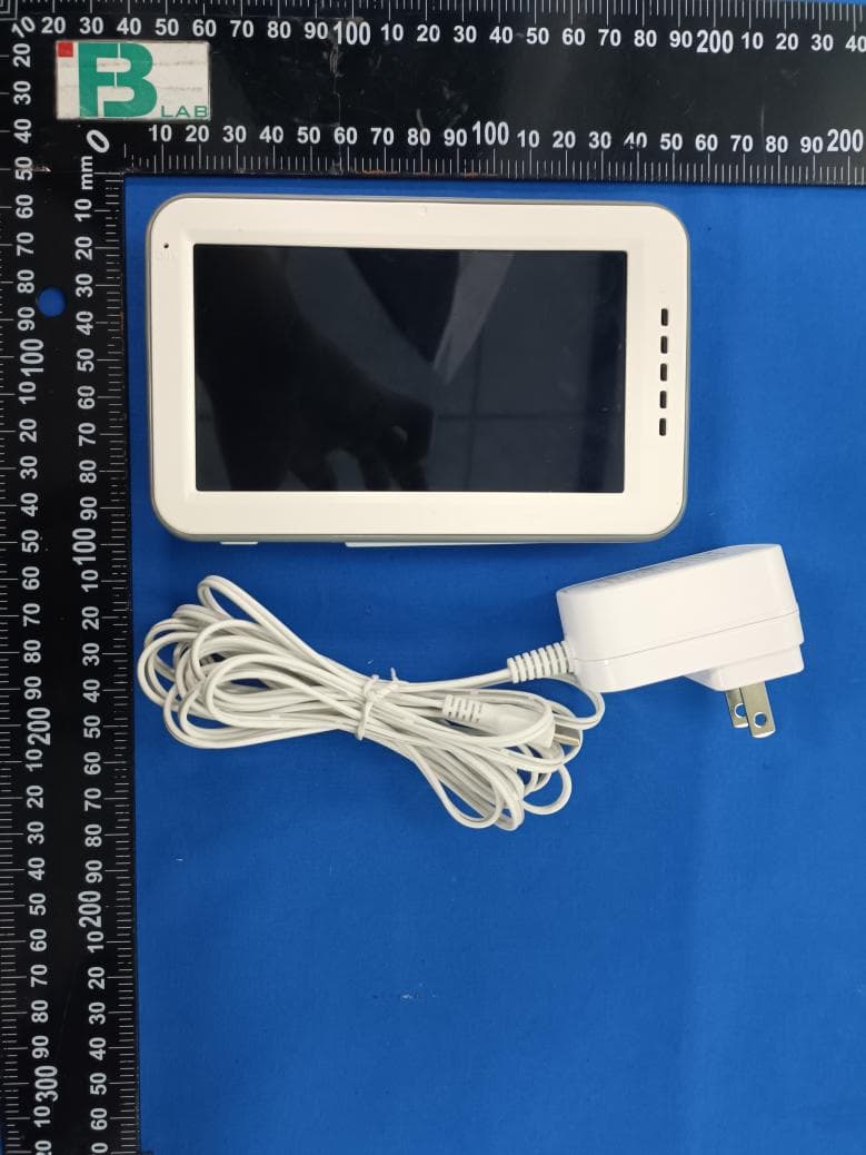
SJ8M514
Dec 14, 2023Wireless 5 LCD Monitor
Equipment Class
DTS - Digital Transmission System