SJ8WL24GGame Link
RDI Technology (Shenzhen) Co., Ltd.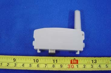
Click to zoom
Application Details
- Equipment Class
- DXX - Part 15 Low Power Communication Device Transmitter
- Date of Grant
- Nov 14, 2004
- Application Purpose
- Original Equipment
- Date of Application
- Nov 14, 2004
- Equipment Note
- Game Link
- Frequency Range
- 2404.00000000 - 2480.00000000
- Country
- China
Documents & Files
Document Text
Text extracted from the exhibit documents filed with the FCC. Open a document above to read the original.
Users Manual
Wireless Game Link Description Wireless Game Link (Game Link) is a low cost wireless replacement for the Multiboot game cable used by both the standard and SP version of the Game Boy Advance (GBA). It is designed to simply replace the wired connection and operate transparently for all multiplayer games that are supported by the standard cable and use the standard serial port communication protocol. Game Link will support up to four simultaneous connections at distances up to 9 feet.It uses a low power transmission circuit combined with enhanced sensitivity.This allows it to operate directly from power drawn from the serial port to which it connects. It operates in the 2.4GHz spectrum so it can be licensed for operation in the US and most other countries Game Link is simple to use.It is a “nub” that is plugged into each of the serial ports of the GBA’s that are to participate in a multiplayer game session.When powered up, each Game Link in range of each other will form a connection (up to four). The status LED on each Game Link will go solid to signify a connection is made.If the players start to walk away, the LED indicator will start to slow flash as a warning when they are leaving range.Once out of range, the LED will rapidly flash until a connection is reestablished by going back in range and cycling power. Both multiboot and multiplayer modes are supported.This allows one standard gaming cartridge to be shared amongst all participants. Directions: 1. Plug the Wireless Link unit into the standard serial expansion port on the back on the Game Boy Advance.This is the same port used for a standard Game Boy Advance Game Link. 2. To use the Wireless Link you must be using Game Boy Advance games that feature multiplayer game play. 3. With your multiplayer game already inserted start up 2 to 4 Game Boy Advance systems with the same multiplayer game (each sold separately).Each system must have a Wireless Link attached (each sold separately). 4. Follow the game’s instructions to start a multiplayer game. 5. Wireless Link will automatically find and link up with other Wireless Link units that are in range for the same game. A constant blinking status light indicates a successful link. An inconsistent,faster blinking status light indicates a poor link.Try moving closer to the other player. FCC NOTE THE MANUFACTURER IS NOT RESPONSIBLE FOR ANY RADIO OR TV INTERFERENCE CAUSED BY UNAUTHORIZED MODIFICATIONS TO THIS EQUIPMENT. SUCH MODIFICATIONS COULD VOID THE USER’S AUTHORITY TO OPERATE THE EQUIPMENT.
Block Diagram
Wireless Game Link Architecture Game Link takes advantage of the half-duplex, token-ring protocol used by the multiboot cable. It implements a proprietary wireless protocol that is similar in timing to the wired one.This allows for operation that appears transparent to standard games.This protocol also transparently implements error correction and retransmission of lost or catastrophically corrupted packets. The hardware is comprised of three chips, the transceiver chip CC2400,the baseband chip C8051F331 and the RF switch PE4259.The baseband chip is a masked programmed Micro Controller Unit (MCU) based around an ARM core,the MCU control the RF switch On/Off and the transceiver chip to receive and transmit valid signal so that achieve all communication with other Game Link Unit.Figure 1 shows a simple block diagram of the Game Link. Figure 1 Game Link MCU RF switch Transceive r Chip 18MHz Dual Antennas For Diversity Game Boy
External Photos
EUT - Front View EUT - Back View
ID Label/Location Info
FCC ID Label Location This device complies with Part 15 of the FCC Rules. Operation is subject to the following two conditions:(1) this device may not cause harmful interference, and (2) this device must accpt any interference received, including interference that may cause undesired operation The Label must not be a stick-on paper. The Label on these products must be permanently affixed to the product and readily visible at the time of purchase and must last the expected lifetime of the equipment not be readily detachable. Proposed Label Location on EUT EUT Bottom View/proposed FCC Mark Location For Home or Offi ce Use
ID Label/Location Info
FCC ID Label Sample for Model Wireless Link FCC ID: SJ8WL24G Made in China This device complies with Part 15 of the FCC Rules. Operation is subject to the following two conditions: 1. This device may not cause harmful interference, and 2. This device must accept any interference received, including interference that may cause undesired operation.
Internal Photos
PCB - Component View PCB - Solder View
Operational Description
Operational description Game Link takes advantage of the half-duplex, token-ring protocol used by the multiboot cable. It implements a proprietary wireless protocol that is similar in timing to the wired one.This allows for operation that appears transparent to standard games.This protocol also transparently implements error correction and retransmission of lost or catastrophically corrupted packets. The hardware is comprised of three chips, the transceiver chip CC2400,the baseband chip C8051F331 and the RF switch PE4259.The baseband chip is a masked programmed Micro Controller Unit (MCU) based around an ARM core,the MCU control the RF switch On/Off and the transceiver chip to receive and transmit valid signal so that achieve all communication with other Game Link Unit.Figure 1 shows a simple block diagram of the Game Link. Figure 1 Game Link MCU RF switch Transceive r Chip Dual Antennas For Diversity Game Boy
Test Report
FCC TEST REPORT FCC ID : SJ8WL24G Applicant : Shenzhen RDI Electronics & Plastics Co., Ltd. Building C2 Xingtang Industrial Park, East Baishixia, Fuyong, Baoan, Shenzhen, PRC Equipment Under Test (EUT) : Product description : Game Link Model No. : Wireless Link Standards : FCC 15 Paragraph 15.205, Paragraph 15.209, Paragraph 15.31, Paragraph 15.33, Paragraph 15.35, Paragraph 15.249 Date of Test : November 08, 2004 Test Engineer : Jimmy Lee Reviewed By : PERPARED BY: Shenzhen Huatongwei International Inspection Co., Ltd Keji S,12th,Road, Hi-tech Industrial Park, Shenzhen, Guangdong, China FCC Registration Number: 662850 Page 1 of 26 Shenzhen RDI Electronics & Plastics Co., Ltd. FCC ID:SJ8WL24G 2 Contents Page 1 COVER PAGE..........................................................................................................................................................1 2 CONTENTS..............................................................................................................................................................2 3 TEST SUMMARY....................................................................................................................................................5 4 GENERAL INFORMATION..................................................................................................................................5 4.1 CLIENT INFORMATION............................................................................................................................................5 4.2 GENERAL DESCRIPTION OF E.U.T...........................................................................................................................5 4.3 DETAILS OF E.U.T..................................................................................................................................................5 4.4 DESCRIPTION OF SUPPORT UNITS...........................................................................................................................5 4.5 STANDARDS APPLICABLE FOR TESTING..................................................................................................................5 4.6 TEST FACILITY........................................................................................................................................................6 4.7 TEST LOCATION......................................................................................................................................................6 5 EQUIPMENT USED DURING TEST...................................................................................................................7 6 CONDUCTED EMISSION TEST..........................................................................................................................8 6.1 TEST EQUIPMENT....................................................................................................................................................8 6.2 TEST PROCEDURE...................................................................................................................................................8 6.3 CONDUCTED TEST SETUP.......................................................................................................................................9 6.4 EUT OPERATING CONDITION.................................................................................................................................9 6.5 CONDUCTED EMISSION LIMITS.............................................................................................................................10 6.6 CONDUCTED EMISSION TEST RESULT...................................................................................................................10 7 RADIATION EMISSION TEST...........................................................................................................................11 7.1 TEST EQUIPMENT..................................................................................................................................................11 7.2 MEASUREMENT UNCERTAINTY.............................................................................................................................11 7.3 TEST PROCEDURE.................................................................................................................................................11 7.4 RADIATED TEST SETUP.........................................................................................................................................12 7.5 SPECTRUM ANALYZER SETUP...............................................................................................................................12 7.6 CORRECTED AMPLITUDE & MARGIN CALCULATION............................................................................................13 7.7 SUMMARY OF TEST RESULTS................................................................................................................................13 7.8 EUT OPERATING CONDITION...............................................................................................................................14 7.9 RADIATED EMISSIONS LIMIT.................................................................................................................................14 7.10 RADIATED EMISSIONS TEST RESULT................................................................................................................15 8 BAND EDGE..........................................................................................................................................................19 8.1 TEST EQUIPMENT..................................................................................................................................................19 8.2 TEST PROCEDURE.................................................................................................................................................19 8.3 RADI…
Text truncated - open the document above for the full version.
Test Setup Photos
Test Setup Photos
Contact Information
Applicant
Yuan Mike(Vice General Manager)
Test Firm
Shenzhen Huatongwei International Insp. Co., LtdMoffy Yu
Technical Specifications
| # | Rule Parts | Frequency Range | Power Output |
|---|---|---|---|
| 1 | 15C | 2.40 GHz - 2.48 GHz | - |
Other Applications from RDI Technology (Shenzhen) Co., Ltd.
SJ8-VC160
Jan 08, 2026Wireless Camera
Equipment Class
NII - Unlicensed National Information Infrastructure TXSJ8-M125
Jan 07, 2026Wireless Monitor
Equipment Class
NII - Unlicensed National Information Infrastructure TXSJ8-VC46
Dec 10, 2025Wireless Camera
Equipment Class
DTS - Digital Transmission System
SJ8-M124EI
Aug 08, 2024Wireless Monitor
Equipment Class
DTS - Digital Transmission System
SJ8M514
Dec 14, 2023Wireless 5 LCD Monitor
Equipment Class
DTS - Digital Transmission System