SJ8WM90228GB MESSENGER
RDI Technology (Shenzhen) Co., Ltd.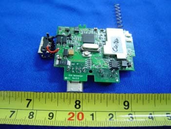
Click to zoom
Application Details
- Equipment Class
- DXX - Part 15 Low Power Communication Device Transmitter
- Date of Grant
- Dec 29, 2004
- Application Purpose
- Original Equipment
- Date of Application
- Dec 29, 2004
- Equipment Note
- GB MESSENGER
- Frequency Range
- 902.00000000 - 928.00000000
- Country
- China
Documents & Files
Document Text
Text extracted from the exhibit documents filed with the FCC. Open a document above to read the original.
Users Manual
GB Messenger for the GBA GB Messenger is a low cost radio-messaging cartridge for the Game Boy Advance. It lets Game Boy Advance users send text messages to each other when they are within up to a 3-mile radius in rural settings and several city blocks in city settings. The GB Messenger user experience is similar to that of a two-way pager or other message services such as those on most cell phones.However, GB Messenger does not use cellular or paging infrastructure and hence requires no registration or license and is totally free to use. Text messages are constructed and sent with a virtual keypad that is displayed on the GBA screen.Navigation though the keypad is done quickly with the arrow key (D key). Messages can be sent to individuals or to groups of individuals at the same time.Users can also query to see what other GB Messenger units are online.Users can assign unique names to their units.These names or “handles” are what is reported in a query. Users can also request confirmation that a message they sent has been successfully received. When a message is received, it is stored in flash memory.The Message LED is then flashed until all received messages have been read. If the unit is plugged into a GBA that is turned on, an audible alert is played through the GBA speaker until any button is pushed. Message management is done on-screen and up to 30 messages can be saved in internal flash. GB Messenger is powered on or off through user input via the GBA. When removed from the GBA it will stay in the same power state it was in when it was removed.When powered on, the Active LED flashes. When powered off, the Active LED stays off. GB Messenger has its own internal, rechargeable lithium ion battery that allows it to receive messages even when it is not plugged into a GBA. The condition of this battery is monitored and reported both on-screen and via the Active LED.If the battery is low, the activity indicator changes its alert cadence to indicate this. When plugged into a GBA that is powered on, the battery will trickle charge from the GBA bus.For fast charging, the user can also plug the standard SP charger directly into the receptacle on its side. GB Messenger is targeted at a preteen and early-teen age group.Most friends in this age group attend the same schools and live locally within the same neighborhood.Hence, a 3- mile range would provide effective coverage for most users in this demographic. FCC NOTE: THE MANUFACTURER IS NOT RESPONSIBLE FOR ANY RADIO OR TV INTERFERENCE CAUSED BY UNAUTHORIZED MODIFICATIONS TO THIS EQUIPMENT. SUCH MODIFICATIONS COULD VOID THE USER’S AUTHORITY TO OPERATE THE EQUIPMENT.
Block Diagram
GB Messenger for the GBA Block Diagram MCU A/D Flash SPI GPIO CC1020 Single Chip Transceiver Data/En Switch RF PA Filter T X RX Control 3 Data Serial Flash GPIO SP Charge P ort LED X2 Duplex Register GBA Bus Control Power Supply To: RF To: MCU Li+ Battery Figure 1 3 Enable Charge Control GPIO GPIO 2 8 Data Control 3 Control GBA ROM Data 16 8 Data 3 2 3.3 V 14.7456Mhz
External Photos
EUT - Front View EUT - Back View
ID Label/Location Info
FCC ID Label Location This device complies with Part 15 of the FCC Rules. Operation is subject to the following two conditions:(1) this device may not cause harmful interference, and (2) this device must accpt any interference received, including interference that may cause undesired operation The Label must not be a stick-on paper. The Label on these products must be permanently affixed to the product and readily visible at the time of purchase and must last the expected lifetime of the equipment not be readily detachable. Proposed Label Location on EUT EUT Bottom View/proposed FCC Mark Location For Home or Office Use
Internal Photos
PCB - Component View (1) PCB - Component View(2) PCB - Solder View
Test Report
FCC TEST REPORT FCC ID : SJ8WM90228 Applicant : Shenzhen RDI Electronics & Plastics Co., Ltd. Building C2 Xingtang Industrial Park, East Baishixia, Fuyong, Baoan, Shenzhen, PRC Equipment Under Test (EUT) : Product description : GB Messenger Model No. : Wireless Messenger Standards : FCC 15 Paragraph 15.205, Paragraph 15.209, Paragraph 15.31, Paragraph 15.33, Paragraph 15.35, Paragraph 15.249 Date of Test : December 08, 2004 Test Engineer : Jimmy Lee Reviewed By : PERPARED BY: Shenzhen Huatongwei International Inspection Co., Ltd Keji S,12th,Road, Hi-tech Industrial Park, Shenzhen, Guangdong, China FCC Registration Number: 662850 Page 1 of 29 Shenzhen RDI Electronics & Plastics Co., Ltd. FCC ID:SJ8WM90228 2 Contents Page 1 COVER PAGE..........................................................................................................................................................1 2 CONTENTS..............................................................................................................................................................2 3 TEST SUMMARY....................................................................................................................................................5 4 GENERAL INFORMATION..................................................................................................................................5 4.1 CLIENT INFORMATION............................................................................................................................................5 4.2 GENERAL DESCRIPTION OF E.U.T...........................................................................................................................5 4.3 DETAILS OF E.U.T..................................................................................................................................................5 4.4 DESCRIPTION OF SUPPORT UNITS...........................................................................................................................5 4.5 STANDARDS APPLICABLE FOR TESTING..................................................................................................................5 4.6 TEST FACILITY........................................................................................................................................................6 4.7 TEST LOCATION......................................................................................................................................................6 5 EQUIPMENT USED DURING TEST...................................................................................................................7 6 CONDUCTED EMISSION TEST..........................................................................................................................8 6.1 TEST EQUIPMENT....................................................................................................................................................8 6.2 TEST PROCEDURE...................................................................................................................................................8 6.3 CONDUCTED TEST SETUP.......................................................................................................................................9 6.4 EUT OPERATING CONDITION.................................................................................................................................9 6.5 CONDUCTED EMISSION LIMITS.............................................................................................................................10 6.6 CONDUCTED EMISSION TEST RESULT...................................................................................................................10 7 RADIATION EMISSION TEST...........................................................................................................................11 7.1 TEST EQUIPMENT..................................................................................................................................................11 7.2 MEASUREMENT UNCERTAINTY.............................................................................................................................11 7.3 TEST PROCEDURE.................................................................................................................................................11 7.4 RADIATED TEST SETUP.........................................................................................................................................12 7.5 SPECTRUM ANALYZER SETUP...............................................................................................................................12 7.6 CORRECTED AMPLITUDE & MARGIN CALCULATION............................................................................................13 7.7 SUMMARY OF TEST RESULTS................................................................................................................................13 7.8 EUT OPERATING CONDITION...............................................................................................................................14 7.9 RADIATED EMISSIONS LIMIT.................................................................................................................................14 7.10 RADIATED EMISSIONS TEST RESULT................................................................................................................15 8 BAND EDGE..........................................................................................................................................................21 8.1 TEST PROCEDURE.................................................................................................................................................21 8.2 BAND EDGE......................................................................................................................................................…
Text truncated - open the document above for the full version.
Test Setup Photos
Test Setup Photos
Contact Information
Applicant
Yuan Mike(Vice General Manager)
Test Firm
Shenzhen Huatongwei International Insp. Co., LtdMoffy Yu
Technical Specifications
| # | Rule Parts | Frequency Range | Power Output |
|---|---|---|---|
| 1 | 15C | 902 MHz - 928 MHz | - |
Other Applications from RDI Technology (Shenzhen) Co., Ltd.
SJ8-VC160
Jan 08, 2026Wireless Camera
Equipment Class
NII - Unlicensed National Information Infrastructure TXSJ8-M125
Jan 07, 2026Wireless Monitor
Equipment Class
NII - Unlicensed National Information Infrastructure TXSJ8-VC46
Dec 10, 2025Wireless Camera
Equipment Class
DTS - Digital Transmission System
SJ8-M124EI
Aug 08, 2024Wireless Monitor
Equipment Class
DTS - Digital Transmission System
SJ8M514
Dec 14, 2023Wireless 5 LCD Monitor
Equipment Class
DTS - Digital Transmission System