SJ8XWS150D-SWIRELESS DOOR SENSOR
RDI Technology (Shenzhen) Co., Ltd.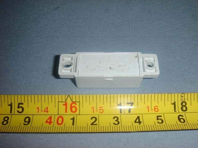
Click to zoom
Application Details
- Equipment Class
- DSC - Part 15 Security/Remote Control Transmitter
- Date of Grant
- Nov 13, 2007
- Application Purpose
- Original Equipment
- Date of Application
- Nov 12, 2007
- Equipment Note
- WIRELESS DOOR SENSOR
- Frequency Range
- 418.00000000 - 418.00000000
- Country
- China
Documents & Files
Document Text
Text extracted from the exhibit documents filed with the FCC. Open a document above to read the original.
Users Manual
Introduction Congratulations on your purchase of the XANBOO homesight™ Wireless Door/Window Sensor. The Door/Window Sensor uses a magnetic field to enable you to monitor the opening or closing of a door, window, cabinet, or whatever else needs to be checked for movement. This Quick Start Guide describes how to set up and troubleshoot your Door/Window Sensor. Controlling Your Sensor Using your computer and the Wireless System Controller, you locally manage your home environment with the XANBOO homesight software. When configured, the system can notify you of any new events by sending an e-mail when your Door/Window Sensor detects an event. An event is defined as the opening or closing of a door/window/cabinet, etc. How It Works The sensor monitors the status of the magnetic contact. When a change is detected with an opening or closing of a monitored door or window, the sensor sends a notice of the event to your Wireless System Controller, if enabled in Event Setup. The example shows a Door/Window Sensor that has been triggered when the door opens. Installation Overview Your package contains the following: Installing your sensor is a simple process. 1. Insert the batteries. On the bottom of the sensor, slide open the door and insert two AAA alkaline batteries. The back of the battery door of the sensor indicates the polarity (+ and -) of the batteries. Close the door after inserting batteries. 2. Register your sensor with your Wireless System Controller using a process called Discovery. Refer to your homesight Software User Guide for instructions on how to discover your Wireless Door/Window Sensor. Remark: Antenna is permanently attached or has a unique connector Feature Locator Installation Hints Please consider the following points when mounting the sensor: z The XANBOO homesight Door/Window Sensor is constructed of UV resistant ABS plastic allowing for indoor or outdoor use. z The homesight Wireless Door/Window Sensor is constructed of UV-resistant ABS plastic. If installing the Wireless Door/Window Sensor outside, it should be shielded from the elements, such as underneath a porch roof. Do not install the sensor where it is subjected directly to the elements. z Typically, the sensor's wireless reception is good to up to 250 feet from the Wireless System Controller, depending on indoor or outdoor use and the number of obstacles. These can include metal framing, thick walls, and other wireless devices operating at 418 MHz. It is recommended that different positions be tried for optimal results. Installing Your Door/Window Sensor The spacing between the sensor and the contact should be between 1/10 inch and ½ inch (.25 cm to 1.27 cm). Mount Your Door/Window Sensor Discover your sensor before mounting it. 1. Mount Your Door/Window Sensor You can also mount the sensor more securely using the screws in the hardware kit. Using the drilling template found later in this guide, drill two pilot holes for the screws. Affix the screws to one side of the object (typically the "stationary" side) leaving 1/16" (1.6 mm) space between the screw head and the object. Mount the sensor onto the screws and slide down to lock into place. 2. Using the holes on the drilling template, mark the position of the holes to be drilled. For drywall or other composite surfaces use a 7/ 32" drill bit. Drill a hole for each of the mounting screws and insert a plastic wall anchor into each hole. For other solid surfaces use a 1/16" drill bit. Drill a pilot hole for each of the mounting screws. Warning, when mounting near a window, drilling too close to the glass could break the glass and possibly cause it to shatter. The window extends deeper into the frame than can be seen; therefore, ensure your screw is beyond the glass before drilling. 3. The magnetic contact should now be placed on the other side of the object (typically the contact is installed on the side that Install the Magnetic Contact 1. Either peels the paper strip from the double-sided tape located on the back of the contact, or you can more securely attach it using screws in the hardware kit. Remove the cover from the contact and insert the screws through the holes on the top and bottom of the contact. Use the Wall Mounting Drilling template at the end of this guide to assist you. 2. Make sure the magnetic contact aligns with the top of the sensor on either the left or right side. Features and Specifications z Device signal communication z Attaches to any flat non-metal surface z Operates on 2-AAA Alkaline batteries z LED indicator when sensor is triggered Frequency Range: 418 MHz Typical Range Open air (line of sight): 200 feet (60 m) Typical Range Indoors: 60 feet (18 m) Sensor size: 3.43"L × 1.61"W × 0.59"H (87mm × 41mm × 15mm) Wall Mount Drilling Template Mounting tools: Screwdriver, electric drill or awl. On hard surfaces, XANBOO recommends that you pre-drill ½-inch deep pilot holes with a drill bit slightly smaller than the bracket mounting screws before securing the bracket to the surface. When mounting a sensor on soft surfaces like sheetrock, use an awl to punch holes in the material slightly smaller than the plastic anchors included in the hardware mounting kit. The illustration is drawn to a one-to-one scale, which means that it provides the exact dimensions required to mount the unit. Troubleshooting Problem LED does not light up Wireless System Controller does not recognize the sensor during discovery Events are not triggered Sensor continually sends an event Solution Ensure the batteries are properly inserted with the correct polarity. Ensure you are using new AAA batteries. Ensure sensor is powered. Position the sensor in closer proximity to your Wireless System Controller and try again. Ensure there are no other wireless devices interfering with the sensor. The sensor transmits on the 418 MHz frequency. Is the sensor registered with your Wireless System Controller? Ensure that you have the proper settings configured for the sensor Ensure that …
Text truncated - open the document above for the full version.
External Photos
EUT - Front View EUT - Back View EUT – Front View EUT - Back View EUT - Front View EUT - Back View
ID Label/Location Info
FCC ID Label Sample for Model: XWS150D-S FCC ID: SJ8XWS150D-S
ID Label/Location Info
FCC ID Label This device complies with Part 15 of the FCC Rules. Operation is subject to the following two conditions: (1) this device may not cause harmful interference, and (2) this device must accept any interference received, including interference that may cause undesired operation The Label must not be a stick-on paper. The Label on these products must be permanently affixed to the product and readily visible at the time of purchase and must last the expected lifetime of the equipment not be readily detachable. Proposed Label Location on EUT EUT Bottom View/proposed FCC Mark Location FCC ID: SJ8XWS150D-S
Internal Photos
PCB-Front View PCB-Back View
Operational Description
XWS150D-S Sep 17, 2007 Architecture XWS150D-S Wireless Door/Window Sensor, a device uses a magnetic field to enable you to monitor the opening or closing of a door, window, cabinet, or whatever else needs to be checked for movement. The hardware architecture is shown in Figure 1. 1 The unit built-in two reed switches, detects the magnetic field of the magnetic contact. When a change in status is detected with an opening or closing of a monitored door or window, it transmits this event to CC1110 for processing. 2 The CC1110 is a low cost true single UHF transceiver designed for very low power wireless applications. The RF transceiver is integrated with a highly configurable basedband modem. The modem supports various modulation formats and has a configurable data rate up to 500 kbps. 3 The CC1110 deal with kinds of operation, including scanning the discovery switch to initialize communication, monitoring the battery voltage, detecting contact event, flashing the LED to indicate the unit status, and so on. 4 This unit using two AAA alkaline batteries for power supply.
Test Report
FCC TEST REPORT Page 1 of 24 FCC ID : SJ8XWS150D-S Applicant : RDI Technology (Shenzhen) Co., Ltd. Building C1 Xingtang Industrial Park, East Baishixia, Fuyong, Baoan, Shenzhen, P.R.C. Equipment Under Test (EUT) : Product description : Wireless Door Sensor Model No. : XWS150D-S Standards : FCC 15 Subpart C Paragraph 15.231 Date of Test : Nov. 2, 2007 Test Engineer : Tiger Su Reviewed By : PERPARED BY: Waltek Services (Shenzhen) Co., Ltd. 8C,West Tower, Aidi Building, No.5003 Binhe Rd, Futian District, Shenzhen518045, Guangdong, China. Tel: 86-755-83551033 Fax: 86-755-83552400 RDI Technology (Shenzhen) Co., Ltd. FCC ID:SJ8XWS150D-S Page 2 of 24 2 Contents Page 1 COVER PAGE..........................................................................................................................................................1 2 CONTENTS ..............................................................................................................................................................2 3 TEST SUMMARY....................................................................................................................................................4 4 GENERAL INFORMATION..................................................................................................................................5 4.1 CLIENT INFORMATION............................................................................................................................................5 4.2 GENERAL DESCRIPTION OF E.U.T...........................................................................................................................5 4.3 DETAILS OF E.U.T. .................................................................................................................................................5 4.4 DESCRIPTION OF SUPPORT UNITS...........................................................................................................................5 4.5 STANDARDS APPLICABLE FOR TESTING..................................................................................................................5 4.6 TEST FACILITY........................................................................................................................................................6 4.7 TEST LOCATION......................................................................................................................................................6 5 EQUIPMENT USED DURING TEST ...................................................................................................................7 6 CONDUCTED EMISSION TEST ..........................................................................................................................8 6.1 TEST EQUIPMENT....................................................................................................................................................8 6.2 TEST PROCEDURE...................................................................................................................................................8 6.3 CONDUCTED TEST SETUP.......................................................................................................................................9 6.4 EUT OPERATING CONDITION.................................................................................................................................9 6.5 CONDUCTED EMISSION LIMITS.............................................................................................................................10 6.6 CONDUCTED EMISSION TEST DATA......................................................................................................................10 7 RADIATION EMISSION TEST...........................................................................................................................11 7.1 TEST EQUIPMENT..................................................................................................................................................11 7.2 MEASUREMENT UNCERTAINTY.............................................................................................................................11 7.3 TEST PROCEDURE.................................................................................................................................................11 7.4 RADIATED TEST SETUP.........................................................................................................................................12 7.5 SPECTRUM ANALYZER SETUP...............................................................................................................................12 7.6 CORRECTED AMPLITUDE & MARGIN CALCULATION............................................................................................13 7.7 SUMMARY OF TEST RESULTS................................................................................................................................13 7.8 EUT OPERATING CONDITION...............................................................................................................................14 7.9 RADIATED EMISSIONS LIMIT.................................................................................................................................14 7.10 RADIATED EMISSIONS TEST RESULT................................................................................................................15 7.10.1 Radiated Emission Data.............................................................................................................................15 8 PERIODIC OPERATION .....................................................................................................................................17 9 BAND EDGE ..........................................................................................................................................................18 9.1 TEST PROCEDURE.....................................................…
Text truncated - open the document above for the full version.
Test Setup Photos
Radiation Emission Test View For 30MHz-1000MHz Radiation Emission Test View For 1GHz-5GHz
Contact Information
Applicant
Yuan Mike(Vice General Manager)
Test Firm
Shenzhen Academy of Metrology & Quality InspectionPeter Lin
Technical Specifications
| # | Rule Parts | Frequency Range | Power Output |
|---|---|---|---|
| 1 | 15.231 | 418 MHz - 418 MHz | - |
Other Applications from RDI Technology (Shenzhen) Co., Ltd.
SJ8-VC160
Jan 08, 2026Wireless Camera
Equipment Class
NII - Unlicensed National Information Infrastructure TXSJ8-M125
Jan 07, 2026Wireless Monitor
Equipment Class
NII - Unlicensed National Information Infrastructure TXSJ8-VC46
Dec 10, 2025Wireless Camera
Equipment Class
DTS - Digital Transmission System
SJ8-M124EI
Aug 08, 2024Wireless Monitor
Equipment Class
DTS - Digital Transmission System
SJ8M514
Dec 14, 2023Wireless 5 LCD Monitor
Equipment Class
DTS - Digital Transmission System