SK4BP-268DMR digital and analog UHF portable Radio
BridgeIP, LLC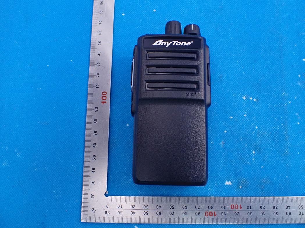
Click to zoom
Application Details
- Equipment Class
- CSR - Scanning Receiver
- Date of Grant
- Jun 29, 2021
- Application Purpose
- Original Equipment
- Date of Application
- Jun 29, 2021
- Equipment Note
- DMR digital and analog UHF portable Radio
- Frequency Range
- 450.00000000 - 512.00000000
- Company
- BridgeIP, LLC
- Country
- United States
Documents & Files
Document Text
Text extracted from the exhibit documents filed with the FCC. Open a document above to read the original.
Users Manual
A1.210619 BridgeIP LLC. 113 South Bridge Street Smithville, MO 64089 Call us at: (816) 532-8451 Visit bridgecomsystems.com for all of your radio support and education needs. Printed in China www.bridgecomsystems.com [email protected] 816-532-8451 BRIDGE PRO 268U Manual WELCOME Thank you for purchasing the Bridge Pro 268U two- way radio. The goal of the BP- 268U is to provide a cost- effective, feature rich, easy- to- use radio. This Owner’s Manual will acquaint you with the features and operation of the BP- 268U. Every effort has been made in the preparation of this manual in order properly operate the radio before use. 1 TABLE OF CONTENTS Safety Information and Safety Warning Accessories Getting Acquainted Basic Operation Programmable Key Function Technical Specifications Warranty and Service FCC Warning and Compliance Statement Page 2, 3 Page 4 Page 5 Page 6 Page 7-10 Page 11 Page 12 Page 13-16 2 SAFETY INFORMATION This radio is for occupational use only, and is to be used under work related conditions. As a user of this radio be fully aware of hazards to RF exposure. The Federal Communications Commission (FCC), with its action in General Docket 93-62, November 7, 1997, has adopted a safety standard for human exposure to Radio Frequency (RF) electromagnetic energy emitted by FCC regulated equipment. Proper operation of this radio will result in user exposure far below the Occupational Safety and Health act (OSHA) and FCC limits. DO NOT transmit for more than a 50% duty cycle (example: 1 min. transmitting, 1 min. receiving or in standby) transmitting more than 50% of the time may cause FCC RF exposure compliance requirements to be exceeded. The radio is transmitting when the red LED is illuminated, hold the radio approximately 1 inch (2.5 cm) away from the MIC located on the front of the radio. The above operating conditions are required for meeting FCC RF exposure compliance, failure to follow these restrictions are considered a violation. 3 SAFETY WARNING Do not transmit the radio without the antenna attached, damaged antenna or touch the antenna while transmitting. Strong electromagnetic waves are emitted from the radio which may damage the radio or cause an RF burn to your skin. Do not use non-approved accessories with your radio. Unauthorized accessories may create unauthorized RF emissions or cause damage to the radio or may result in illegal operation. Do not disassemble or modify the radio, doing so will void the warranty and may result in illegal operation. Do not leave the radio in direct sunlight or around excessive heat, doing so may cause the battery to explode or catch fire. Do not use radio if it has been immersed in water an electronic shock may occur or permanent damage may occur to the radio. 4 1. Standard Accessories Antenna Li-ion Battery Pack ChargerAC Adaptor Belt Clip Wrist strapInstruction Manual 2. Charger Indication ACCESSORIES STATUSLED Self-ExaminationWhen Powered on Red(for 1 second) No BatteryGreen Normal ChargeRed Fully ChargedGreen TroubleRed and green light alternates 5 Antenna Channel Selector VOLUME Switch Led Indicator Speaker Mic-SP jack MIC PF3 KEY PF1 KEY PF2 KEY PTT KEY GETTING ACQUAINTED MIC Indicator Status: 1. Red light flashes: Battery needs charged 2. Red light solid on: Transmit 3. Green light flashe: Scan mode 4. Green light on: Receive matched carrier 5. Blue LED on: Receive matching digital signal 6. Green to White LED on: Programming started 6 BASIC OPERATION Ensure the antenna and a fully charged battery have been properly attached before attempting the following steps. 1. Power on the radio Turn the volume knob clockwise to turn on the radio, after approximately 5 seconds the Green LED will turn on, once illuminated after approximately 5 seconds you will hear a power on beep/announcement. 2. Adjust Volume Turn the volume knob to adjust the volume, clockwise will increase the volume and counter clockwise decreases volume. 3. Selecting a zone Press programmed zone key to change zones with a maximum of 16 channels per zone. 4. Selecting a Channel Turn the channel knob clockwise to select channel positions. 5. Receiving When the radio receives a digital signal, the blue LED turns on. When the radio receives an analog signal, the green LED turns on. Analogue RX: Radio receives a carrier and or with a matched tone to open squelch. Digital RX: When radio receives a correct call with a matched ID, the radio will turn on the speaker to receive voice audio. 6. Make A Call Press and hold PTT, the LED will turn red indicating TX (Transmit), speak clearly into the microphone. 7. Man-down Alarm When the Man-down alarm function is turned on, the radio will alarm when the radio operator/or radio has fallen in a horizontal position. Raising the radio back to a vertical position will stop the alarm. 7 PROGRAMMABLE KEY FUNCTION The PF1, PF2, PF3 keys are programmable by PC software, each key can be enabled up to 3 functions. a short press, a 1 second press or a long press. Consult your radio provider for available functions that have been programmed into your radio. 1. Voltage In standby, press the key programmed as " Voltage" to check current battery capacity. 2. Power Switch In standby, press the key programmed as " Power Switch" to change the power level. 3. Repeater In standby, press the key programmed as " Repeater" to turn on Repeater function, press this key again to turn off repeater function. Note: If current channel is working by repeater frequency, turning off this function, the radio will stop repeater communication. 4. Revers In standby, press the key programmed as "Revers" to turn on frequency revers function, press this key again to turn off revers function. Note: This function is only valid in analog mode, when frequency revers function is on. The TX frequency and RX frequency will be reversed, the CTCSS/DCS will also be reversed. 5. Digital Encryption In standby, press the key programmed as" Digital Encryption", the radio wi…
Text truncated - open the document above for the full version.
Attestation Statements
BridgeIP, LLC ___________________________________________________________________________________________ Date: 2021-06-24 Declaration Letter FEDERAL COMMUNICATIONS COMMISSION Authorization and Evaluation Division 7435 Oakland Mills Road Columbia, MD 21046 Subject: Declaration of compliance to the requirements of §15.121 FCC ID: SK4BP-268 Dear Sir/Madam, We declare that, this scanning receiver is incapable of operating (tuning), or readily being altered by the users to operate, within the frequency bands allocated to the Cellular Radiotelephone Service in part 22 of this chapter (cellular telephone bands). This device will not be able to receive transmissions in the cellular telephone bands by means of clipping the leads of, or installing, a simple component such as a diode, resistor or jumper wire; replacing a plug-in semiconductor chip; or programming a semiconductor chip using special access codes or an external device, such as a personal computer. This device is also incapable of converting digital cellular communication transmissions to analog voice audio. This device is designed so that the tuning, control and filtering circuitry is inaccessible. Any attempts to modify the equipment to receive transmissions from the Cellular Radiotelephone Service will render the receiver inoperable. This scanning receiver rejects any signals from the Cellular Radiotelephone Service frequency bands that are 38 dB or lower based upon a 12 dB SINAD measurement. We are aware that the modification of this device to receive transmissions from Cellular Radiotelephone Service frequency bands will be considered to constitute manufacture of such equipment. This includes any individual, individuals, entity or organization that modifies one or more scanners. Any modification to receive transmissions from the Cellular Radiotelephone Service frequency bands voids the certification of the scanning receiver, regardless of the date of manufacture of the original unit. Sincerely Yours, Signature: ___________________________ Ron Kochanowicz
Cover Letter(s)
BridgeIP, LLC. Agent Authorization Company: BridgeIP, LLC. Address: 113 South Bridge Street Smithville, MO 64089,USA Product Name: DMR digital and analog UHF portable Radio Model Number(s): BP-268 Product Description: DMR digital and analog UHF portable Radio We authorize MiCOM Labs Inc., 575 Boulder Court, Pleasanton, California 94566, USA, to act on our behalf on all matters concerning the certification of above named equipment. We declare that MiCOM Labs Inc. is allowed to forward all information related to the approval and certification of equipment to the regulatory agencies as required and to discuss any issues concerning the approval application. Any and all acts carried out by MiCOM Labs on our behalf shall have the same effect as acts of our own. Signature: Date: 2021-06-28 Name: Ron Kochanowicz Company: BridgeCom Systems, Inc.
Cover Letter(s)
BridgeIP, LLC Office of Engineering Technology Federal Communications Commission 7435 Oakland Mills Road Columbia, MD 21046 USA Date: 2021-06-02 Subject; Request for Confidentiality FCC ID: SK4BP-268 To Whom It May Concern, Pursuant to the provisions of the Commission’s rules Title 47 Sections §0.457 and §0.459, we are requesting the Commission to withhold the following attachment(s) as confidential documents from public disclosure indefinitely. These documents contain detailed system and equipment descriptions and are considered as proprietary information in operation of the equipment. The public disclosure of these documents might be harmful to our company and would give competitors an unfair advantage in the market. Schematic Diagram Block Diagram Parts List Operational Description Tune-up Procedure In additional to above mentioned documents, in order to comply with the marketing regulations in Title 47 CFR §2.803 and the importation rules in Title 47 CFR §2.1204, while ensuring that business sensitive information remains confidential until the actual marketing of newly authorized devices, we request Short Term Confidentiality of the following attachment(s); External Photos Test Setup Photos Internal Photos User Manual For 45 days, pursuant to Public Notice DA 04-1705. OR For 180 days pursuant to KDB 726920 D01. It is our understanding that all measurement test reports, FCC ID label format and correspondence during the certification review process cannot be granted as confidential documents and this information will be available for public review once the grant of equipment authorization is issued. Sincerely BridgeIP, LLC Contact person: Ron Kochanowicz
External Photos
External Photos ALL VIEW OF EUT TOP VIEW OF EUT Antenna BOTTOM VIEW OF EUT FRONT VIEW OF EUT BACK VIEW OF EUT LEFT VIEW OF EUT RIGHT VIEW OF EUT
ID Label/Location Info
FCC ID Label Location 30mm&30mm FCC ID: SK4BP-268
Internal Photos
Internal Photos OPEN VIEW-1 OF EUT OPEN VIEW-1 OF EUT OPEN VIEW-2 OF EUT INTERNAL VIEW-1 OF EUT INTERNAL VIEW-2 OF EUT INTERNAL VIEW-2 OF EUT INTERNAL VIEW-3 OF EUT INTERNAL VIEW-4 OF EUT INTERNAL VIEW-5 OF EUT
Test Report
Page 1 of 27 FCC Test Report Report No.: AGC01284210402FE08 FCC ID : SK4BP-268 PRODUCT DESIGNATION : DMR digital and analog UHF portable Radio BRAND NAME : BridgeCom MODEL NAME : BP-268 APPLICANT : BridgeIP, LLC. DATE OF ISSUE : May 28, 2021 STANDARD(S) : FCC Part 15 Rules REPORT VERSION : V 1.0 Attestation of Global Compliance (Shenzhen) Co., Ltd Report No.: AGC01284210402FE08 Page 2 of 27 REPORT REVISE RECORD Report Version Revise Time Issued Date Valid Version Notes V1.0 / May 28, 2021 Valid Initial Release Report No.: AGC01284210402FE08 Page 3 of 27 TABLE OF CONTENTS 1. VERIFICATION OF COMPLIANCE ................................................................................................................. 4 2. PRODUCT INFORMATION .............................................................................................................................. 5 3. IDENTIFICATION OF THE RESPONSIBLE TESTING LOCATION ............................................................... 6 4. SUPPORT EQUIPMENT LIST ......................................................................................................................... 7 5. SYSTEM DESCRIPTION .................................................................................................................................. 7 6. MEASUREMENT UNCERTAINTY ................................................................................................................... 8 7. SUMMARY OF TEST RESULTS ..................................................................................................................... 8 8. FCC RADIATED EMISSION TEST .................................................................................................................. 9 8.1 PROVISIONS APPLICABLE ................................................................................................................... 9 8.2 TEST SETUP BLOCK DIAGRAM ........................................................................................................... 9 8.3 TEST PROCEDURE .............................................................................................................................. 11 8.4 TEST RESULT ....................................................................................................................................... 12 9. FCC CONDUCTED EMISSION TEST ............................................................................................................ 16 9.1 PROVISIONS APPLICABLE ................................................................................................................. 16 9.2 TEST SETUP BLOCK DIAGRAM ......................................................................................................... 16 9.4 TEST RESULT ................................................................................................................................... 18 10. ANTENNA CONDUCTED POWER FOR RECEIVERS ............................................................................... 20 10.1 PROVISIONS APPLICABLE ............................................................................................................... 20 10.2 TEST SETUP BLOCK DIAGRAM ....................................................................................................... 20 10.3 TEST PROCEDURE ............................................................................................................................ 20 10.4 TEST RESULT ..................................................................................................................................... 21 11. SCANNING RECEIVERS AND FREQUENCY CONVERTERS USED WITH SCANNING RECEIVERS .. 23 11.1 PROVISIONS APPLICABLE ............................................................................................................... 23 11.2 TEST SETUP BLOCK DIAGRAM ....................................................................................................... 23 11.3 TEST PROCEDURE ............................................................................................................................ 23 11.4 TEST RESULT ..................................................................................................................................... 24 APPENDIX I PHOTOGRAPHS OF TEST SETUP ............................................................................................. 25 APPENDIX II: PHOTOGRAPHS OF TEST EUT................................................................................................ 27 Report No.: AGC01284210402FE08 Page 4 of 27 1. VERIFICATION OF COMPLIANCE Applicant: BridgeIP, LLC. Address: 113 South Bridge Street Smithville, MO 64089,USA Manufacturer: BridgeIP, LLC. Address: 113 South Bridge Street Smithville, MO 64089,USA Factory: BridgeIP, LLC. Address: 113 South Bridge Street Smithville, MO 64089,USA Product Designation: DMR digital and analog UHF portable Radio Brand Name: BridgeCom Test Model: BP-268 Measurement Procedure: ANSI C63.4: 2014 Deviation: No any deviation from the test method. Date of Test: Apr. 12, 2021~May 28, 2021 Condition of Test Sample: Normal Test Result: Pass Report Template; AGCRT-US-PTT/EMC The above equipment was tested by Attestation Of Global Compliance (Shenzhen) Co., Ltd. for compliance with the requirements set forth in the FCC Rules and Regulations Part 15, the measurement procedure according to ANSI C63.4:2014. This said equipment in the configuration described in this report shows the maximum emission levels emanating from equipment are within the compliance requirements. The test results of this report relate only to the tested sample identified in this report. Prepared By Donjon Huang (Project Engineer) May 28, 2021 Reviewed By Calvin Liu (Reviewer) May 28, 2021 Approved By Forrest Lei Authorized Officer May 28, 2021 Report No.: AGC01284210402FE08 Page 5 of 27 2. PRODUCT INFORMATION The EUT is a DMR digital and analog UHF portable Radio designed for voice communication. It is…
Text truncated - open the document above for the full version.
Test Setup Photos
Test Setup Photos CONDUCTED EMISSION TEST SETUP RADIATED EMISSION TEST SETUP-BELOW 1GHZ RADIATED EMISSION TEST SETUP-ABOVE 1GHZ
Contact Information
Applicant
Ron Kochanowicz
Technical Contact
Test Firm
Attestation of Global Compliance (Shenzhen) Co., LDoris Li
[email protected]+86-755-25234088
Technical Specifications
| # | Rule Parts | Frequency Range | Power Output |
|---|---|---|---|
| 1 | 15B | 450 MHz - 512 MHz | - |
Other Applications from BridgeIP, LLC

SK4BP-268V
May 04, 2023DMR digital and analog VHF portable Radio
Equipment Class
TNF - Licensed Non-Broadcast Transmitter Held to Face