SK4BP-268VDMR digital and analog VHF portable Radio
BridgeIP, LLC
Click to zoom
Application Details
- Equipment Class
- TNF - Licensed Non-Broadcast Transmitter Held to Face
- Date of Grant
- May 04, 2023
- Application Purpose
- Original Equipment
- Date of Application
- May 04, 2023
- Equipment Note
- DMR digital and analog VHF portable Radio
- Frequency Range
- 136.00000000 - 174.00000000
- Company
- BridgeIP, LLC
- Country
- United States
Documents & Files
Document Text
Text extracted from the exhibit documents filed with the FCC. Open a document above to read the original.
Users Manual
BRIDGE PRO 268 Manual www.bridgecomsystems.com [email protected] 816-532-8451 WELCOME Thank you for purchasing the Bridge Pro 268 series of two-way radio. The goal of the BP-268 series to provide a cost-effective, feature rich, easy-to-use radio. This Owner’s Manual will acquaint you with the features and operation of the BP-268 series. Every effort has been made in the preparation of this manual in order properly operate the radio before use. This manual is applicable to BP-268 and BP-268V version. TABLE OF CONTENTS Safety Information and Safety Warning Page 2, 3 Accessories Page 4 Getting Acquainted Page 5 Basic Operation Page 6, 7 Programmable Key Function Page 8- 12 Technical Specifications Page 13 Warranty and Service Page 14 FCC Warning and Compliance Statement Page 15 1 SAFETY INFORMATION This radio is for occupational use only, and is to be used under work related conditions. As a user of this radio be fully aware of hazards to RF exposure. The Federal Communications Commission (FCC), with its action in General Docket 93-62, November 7, 1997, has adopted a safety standard for human exposure to Radio Frequency (RF) electromagnetic energy emitted by FCC regulated equipment. Proper operation of this radio will result in user exposure far below the Occupational Safety and Health act (OSHA) and FCC limits. DO NOT transmit for more than a 50% duty cycle (example: 1 min. transmitting, 1 min. receiving or in standby) transmitting more than 50% of the time may cause FCC RF exposure compliance requirements to be exceeded. The radio is transmitting when the red LED is illuminated, hold the radio approximately 1 inch (2.5 cm) away from the MIC located on the front of the radio. The above operating conditions are required for meeting FCC RF exposure compliance, failure to follow these restrictions are considered a violation. 2 SAFETY WARNING Do not transmit the radio without the antenna attached, damaged antenna or touch the antenna while transmitting. Strong electromagnetic waves are emitted from the radio which may damage the radio or cause an RF burn to your skin. Do not use non-approved accessories with your radio. Unauthorized accessories may create unauthorized RF emissions or cause damage to the radio or may result in illegal operation. Do not disassemble or modify the radio, doing so will void the warranty and may result in illegal operation. Do not leave the radio in direct sunlight or around excessive heat, doing so may cause the battery to explode or catch fire. Do not use radio if it has been immersed in water an electronic shock may occur or permanent damage may occur to the radio. 3 ACCESSORIES Standard Accessories Charger Indication STATUS Self -Examination When Powered on Normal ChargeFully Charged Trouble LED Red(for 1 second) Green Red Green Red and green light alternates 4 Ante nna Li-ion Battery Pack ChargerAC Adaptor Belt ClipHand StrapInstruction Manual No Battery GETTING ACQUAINTED 5 Antenna Channel Se lector VOLUME Switch Led Indicator Speaker Mic-SP jack MIC PF3 Key PF1 Key PF2 Key PTT Key MIC Indicator Status: 1. Red light flashes: Battery needs charged 2. Red light solid on: Transmit 3. Green light flashes: Scan mode 4. Green light on: Receive matched carrier 5. Blue LED on: Receive matching digital signal 6. G reen to White LED on: Programming started BASIC OPERATION Ensure the antenna and a fully charged battery have been properly attached before attempting the following steps. 1.Power on the radio Turn the volume knob clockwise to turn on the radio, after approximately 5 seconds the Green LED will turn on, once illuminated after approximately 5 seconds you will hear a power on beep/announcement. 2. Adjust Volume Turn the volume knob to adjust the volume, clockwise will increase the volume and counter clockwise decreases volume. 3.Selecting a zone Press programmed zone key to change zones with a maximum of 16 channels per zone. 4.Selecting a Channel Turn the channel knob clockwise to select channel positions. 5.Receiving When the radio receives a digital signal, the blue LED turns on. When the radio receives an analog signal, the green LED turns on. ●Analogue RX: Radio receives a carrier and or with a matched tone to open squelch. ●Digital RX: When radio receives a correct call with a matched ID, the radio will turn on the speaker to receive voice audio. 6.Make A Call Press and hold PTT, the LED will turn red indicating TX (Transmit), speak clearly into the microphone 6 7.Man-down Alarm When the Man-down alarm function is turned on, the radio will alarm when the radio operator/or radio has fallen in a horizontal position. Raising the radio back to a vertical position will stop the alarm. 7 PROGRAMMABLE KEY FUNCTION The PF1, PF2, PF3 keys are programmable by PC software, each key can be enabled up to 3 functions. a short press, a 1 second press or a long press. Consult your radio provider for available functions that have been programmed into your radio. 1. Voltage In standby, press the key programmed as " Voltage" to check current battery capacity. 2.Power Switch In standby, press the key programmed as " Power Switch" to change the power level. 3.Repeater In standby, press the key programmed as " Repeater" to turn on Repeater function, press this key again to turn off repeater function. Note: If current channel is working by repeater frequency, turning off this function, the radio will stop repeater communication. 4.Reverse In standby, press the key programmed as "Revers" to turn on frequency revers function, press this key again to turn off revers function. Note: This function is only valid in analog mode, when frequency revers function is on. The TX frequency and RX frequency will be reversed, the CTCSS/DCS will also be reversed. 5.Digital Encryption In standby, press the key programmed as" Digital Encryption", the radio will announce encryption status or encryption group. Press this key again to choose encryption group or turn off encryption. Note:…
Text truncated - open the document above for the full version.
Attestation Statements
BridgeIP, LLC 113 S. Bridge St. Smithville, MO 64089, United States Federal Communications Commission Authorization and Evaluation Division 7435 Oakland Mills Road Columbia, MD 21046 USA Date: Apr. 19, 2023 Ref: Attestation Statements Part 2.911(d)(5)(i) Filing FCC ID: SK4BP-268V Product Name: DMR digital and analog VHF portable Radio Model Name: BP-268V [BridgeIP, LLC] (“the applicant”) certifies that the equipment for which authorization is sought is not “covered” equipment prohibited from receiving an equipment authorization pursuant to section 2.903 of the FCC rules. Sincerely, (Applicant signature) Name: Ron Kochanowicz Title: General Manager
Cover Letter(s)
BridgeIP, LLC 113 S. Bridge St. Smithville, MO 64089, United States Date: 2023-04-19 FCC Part 90 Letter FEDERAL COMMUNICATIONS COMMISSION Authorization and Evaluation Division 7435 Oakland Mills Road Columbia, MD 21046 Subject: Declaration of compliance to the requirements of §90.203 With FCC ID: SK4BP-268V Dear Sir/Madam, We, BridgeIP, LLC., acknowledge that this device will not be marketed to USA users with the frequency band which is not allowed by rule part 90.and it is a violation of FCC rules if this device is operated on unauthorized frequencies inside the U.S.A. This equipment meets the requirements of the FCC Rules, Parts 90.203(e) and (g), as applicable. Programming of this products transmit frequencies can be performed ONLY by the manufacturer or by service or by maintenance personal. The operator can’t program transmit frequencies using the equipment’s external operation controls. This is to certify that the requirements of 47 CFR Part 90.203(j)(4) and (5) spectrum efficiency are met by the BridgeIP, LLC. demonstrated by the tests conducted on the sample radio provided. The tests show that the 4FSK data rate is in accordance with ETSI TS 102 361-1, that is 9600 bits per second in a 12.5 kHz bandwidth to satisfy the data rate requirement of 4800 bits per second per 6.25 kHz of channel bandwidth (7K60F1D emissions). Additionally the radio uses the AMBE+2 half-rate vocoder to compress 60 ms of normal bursts are sent in alternate 30 ms TDMA slots and so comply with the equivalence of one voice channel per 6.25 kHz bandwidth (7K60F1W emission). Additionally the radio also meets the requirement of one voice channel per 12.5 kHz of channel bandwidth for analogue speech (11k0F3E emission). Sincerely Yours, Signature: ___________________________ Ronald G Kochanowicz President/CEO
Cover Letter(s)
BridgeIP, LLC 113 S. Bridge St. Smithville, MO 64089, United States Agent Authorization Company: BridgeIP, LLC Address: 113 S. Bridge St. Smithville, MO 64089, United States Product Name: DMR digital and analog VHF portable Radio Model Number(s): BP-268V Product Description: DMR digital and analog VHF portable Radio We authorize MiCOM Labs Inc., 575 Boulder Court, Pleasanton, California 94566, USA, to act on our behalf on all matters concerning the certification of above named equipment. We declare that MiCOM Labs Inc. is allowed to forward all information related to the approval and certification of equipment to the regulatory agencies as required and to discuss any issues concerning the approval application. Any and all acts carried out by MiCOM Labs on our behalf shall have the same effect as acts of our own. Signature: Date: Apr. 19, 2023 Name: Ron Kochanowicz Title: General Manager Company: BridgeIP, LLC
External Photos
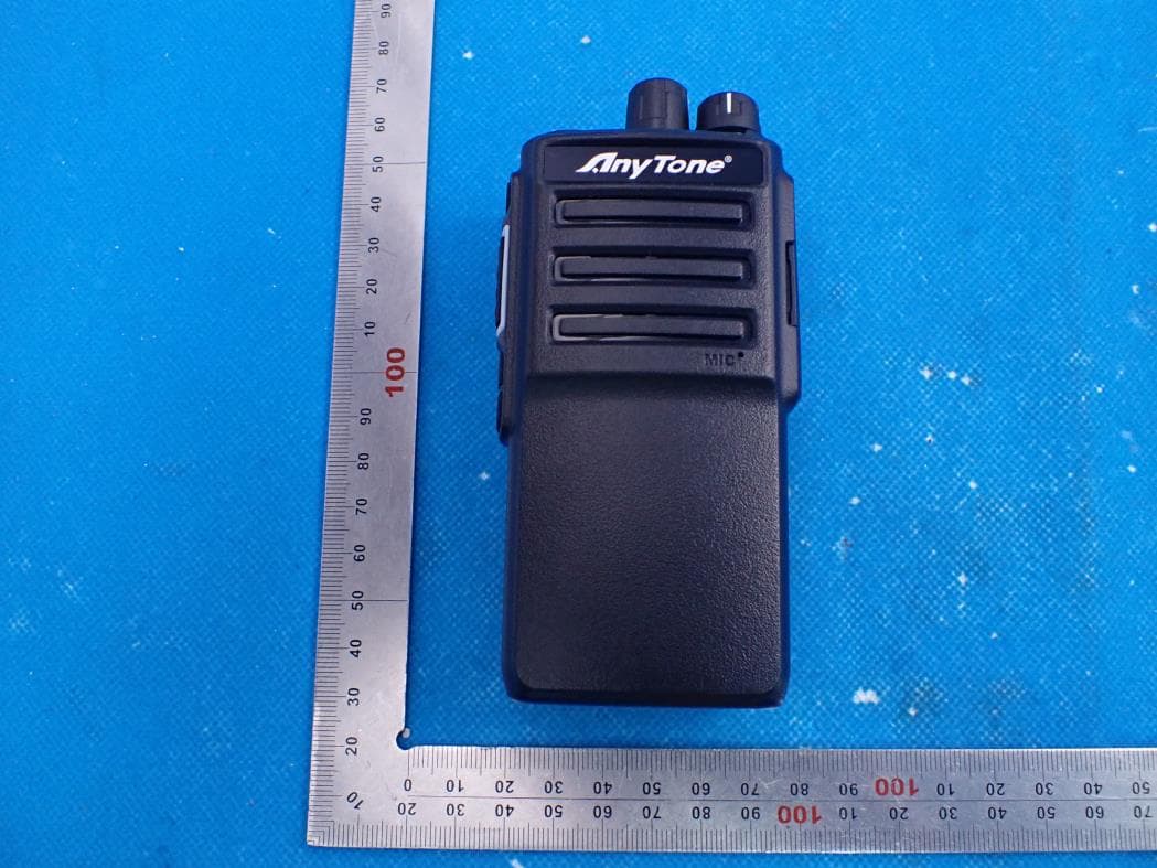
Report No.: AGC01284230402AP02 Page 1 of 4 EXTERNAL PHOTOS All VIEW OF EUT TOP VIEW OF EUT DMR Antenna Report No.: AGC01284230402AP02 Page 2 of 4 BOTTOM VIEW OF EUT FRONT VIEW OF EUT Report No.: AGC01284230402AP02 Page 3 of 4 BACK VIEW OF EUT LEFT VIEW OF EUT Report No.: AGC01284230402AP02 Page 4 of 4 RIGHT VIEW OF EUT ****************************************End of Report*************************************
ID Label/Location Info
FCC ID Label Location 10mm*10mm FCC ID: SK4BP-268V
Internal Photos
Report No.: AGC01284230402AP02 Page 1 of 7 INTERNAL PHOTOS OPEN VIEW OF EUT(FIGURE 1) OPEN VIEW OF EUT(FIGURE 2) Report No.: AGC01284230402AP02 Page 2 of 7 OPEN VIEW OF EUT(FIGURE 3) INTERNAL VIEW OF EUT(FIGURE 1) Report No.: AGC01284230402AP02 Page 3 of 7 INTERNAL VIEW OF EUT(FIGURE 2) INTERNAL VIEW OF EUT(FIGURE 3) Report No.: AGC01284230402AP02 Page 4 of 7 INTERNAL VIEW OF EUT(FIGURE 4) INTERNAL VIEW OF EUT(FIGURE 5) Report No.: AGC01284230402AP02 Page 5 of 7 INTERNAL VIEW OF EUT(FIGURE 6) INTERNAL VIEW OF EUT(FIGURE 7) Report No.: AGC01284230402AP02 Page 6 of 7 INTERNAL VIEW OF EUT(FIGURE 8) INTERNAL VIEW OF EUT(FIGURE 9) Report No.: AGC01284230402AP02 Page 7 of 7 INTERNAL VIEW OF EUT(FIGURE 10) ****************************************End of Report*************************************
RF Exposure Info
Page 1 of 41 SAR Test Report Report No.: AGC01284230402FH01 FCC ID : SK4BP-268V PRODUCT DESIGNATION : DMR digital and analog VHF portable Radio BRAND NAME : BridgeCom MODEL NAME : BP-268V APPLICANT : BridgeIP, LLC DATE OF ISSUE : Apr. 19, 2023 STANDARD(S) : IEEE Std. 1528:2013 FCC 47 CFR Part 2§2.1093 IEEE Std C95.1 ™-2005 IEC 62209-1: 2016 REPORT VERSION : V1.0 Attestation of Global Compliance(Shenzhen) Co., Ltd. Report No.: AGC01284230402FH01 Page 2 of 41 Report Revise Record Report Version Revise Time Issued Date Valid Version Notes V1.0 / Apr. 19, 2023 Valid Initial Release Report No.: AGC01284230402FH01 Page 3 of 41 Test Report Applicant Name BridgeIP, LLC Applicant Address 113 S. Bridge St. Smithville, MO 64089, United States Manufacturer Name Qixiang Electron Science & Technology Co., Ltd. Manufacturer Address Qixiang Building, Tangxi Industrial Zone, Luojiang District, Quanzhou, Fujian, China Factory Name Qixiang Electron Science & Technology Co., Ltd. Factory Address Qixiang Building, Tangxi Industrial Zone, Luojiang District, Quanzhou, Fujian, China Product Designation DMR digital and analog VHF portable Radio Brand Name BridgeCom Model Name BP-268V Different Description N/A EUT Voltage DC7.4 V Applicable Standard IEEE Std. 1528:2013 FCC 47 CFR Part 2§2.1093 IEEE Std C95.1 ™-2005 IEC 62209-1: 2016 Date of receipt of test item Apr. 03, 2023 Test Date Apr. 07, 2023 Report Template AGCRT- US -PTT/SAR (2021-04-20) Note: The results of testing in this report apply to the product/system which was tested only. Prepared By Thea Huang (Project Engineer) Apr. 07, 2023 Reviewed By Calvin Liu (Reviewer) Apr. 19, 2023 Approved By Max Zhang (Authorized Officer) Apr. 19, 2023 Report No.: AGC01284230402FH01 Page 4 of 41 TABLE OF CONTENTS 1. SUMMARY OF MAXIMUM SAR VALUE ......................................................................................................... 5 2. GENERAL INFORMATION ............................................................................................................................... 6 2.1. EUT DESCRIPTION......................................................................................................................................... 6 3. SAR MEASUREMENT SYSTEM ........................................................................................................................ 7 3.1. THE DASY5 SYSTEM USED FOR PERFORMING COMPLIANCE TESTS CONSISTS OF FOLLOWING ITEMS .................... 7 3.2. DASY5 E-FIELD PROBE ................................................................................................................................. 8 3.3. DATA ACQUISITION ELECTRONICS DESCRIPTION ............................................................................................... 8 3.4. ROBOT .......................................................................................................................................................... 9 3.5. LIGHT BEAM UNIT .......................................................................................................................................... 9 3.6. DEVICE HOLDER .......................................................................................................................................... 10 3.7. MEASUREMENT SERVER ............................................................................................................................... 10 3.8. PHANTOM ................................................................................................................................................. 11 4. SAR MEASUREMENT PROCEDURE ............................................................................................................ 12 4.1. SPECIFIC ABSORPTION RATE (SAR) .............................................................................................................. 12 4.2. SAR MEASUREMENT PROCEDURE ................................................................................................................ 13 5. TISSUE SIMULATING LIQUID ....................................................................................................................... 15 5.1. THE COMPOSITION OF THE TISSUE SIMULATING LIQUID..................................................................................... 15 5.2. TISSUE DIELECTRIC PARAMETERS FOR HEAD AND BODY PHANTOMS ............................................................... 15 5.3. TISSUE CALIBRATION RESULT ....................................................................................................................... 16 6. SAR SYSTEM CHECK PROCEDURE ........................................................................................................... 17 6.1. SAR SYSTEM CHECK PROCEDURES ............................................................................................................. 17 7. EUT TEST POSITION ...................................................................................................................................... 19 7.1. BODY WORN POSITION ................................................................................................................................ 19 8. SAR EXPOSURE LIMITS ............................................................................................................................... 20 9. TEST FACILITY .............................................................................................................................................. 21 10. TEST EQUIPMENT LIST .............................................................................................................................. 22 11. MEASUREMENT UNCERTAINTY ................................................................................................................ 23 12. POWER MEASUREMENT ............................................................................................................................ 27 13. TEST RESULTS .....................…
Text truncated - open the document above for the full version.
RF Exposure Info
Page 1 of 18 CALIBRATION DATA PROBE CALIBRATION DATA Page 2 of 18 Page 3 of 18 Page 4 of 18 Page 5 of 18 Page 6 of 18 Page 7 of 18 Page 8 of 18 Page 9 of 18 Page 10 of 18 DAE CALIBRATION DATA Page 11 of 18 Page 12 of 18 Page 13 of 18 DIPOLE CALIBRATION DATA DIPOLE CALIBRATION DATA Page 14 of 18 Page 15 of 18 Page 16 of 18 Page 17 of 18 Page 18 of 18
Test Report
Page 1 of 54 FCC Test Report Report No.: AGC01284230402FE10 FCC ID : SK4BP-268V APPLICATION PURPOSE : Original Equipment PRODUCT DESIGNATION : DMR digital and analog VHF portable Radio BRAND NAME : BridgeCom MODEL NAME : BP-268V APPLICANT : BridgeIP, LLC DATE OF ISSUE : Apr. 18, 2023 STANDARD(S) : FCC Part 90 Rules REPORT VERSION : V 1.0 Attestation of Global Compliance (Shenzhen) Co., Ltd Report No.: AGC01284230402FE10 Page 2 of 54 REPORT REVISE RECORD Report Version Revise Time Issued Date Valid Version Notes V1.0 / Apr. 18, 2023 Valid Initial Release Report No.: AGC01284230402FE10 Page 3 of 54 TABLE OF CONTENTS 1. GENERAL INFORMATION .............................................................................................................................. 5 2. PRODUCT INFORMATION .............................................................................................................................. 6 2.1 PRODUCT TECHNICAL DESCRIPTION ................................................................................................ 6 2.2 TEST FREQUENCY LIST ........................................................................................................................ 7 2.3 RELATED SUBMITTAL(S) / GRANT (S) ................................................................................................. 8 2.4 TEST METHODOLOGY .......................................................................................................................... 8 2.5 CALCULATION OF EMISSION INDICATORS ........................................................................................ 8 2.6 SPECIAL ACCESSORIES ....................................................................................................................... 8 2.7 EQUIPMENT MODIFICATIONS .............................................................................................................. 8 3. TEST ENVIRONMENT ..................................................................................................................................... 9 3.1 ADDRESS OF THE TEST LABORATORY .............................................................................................. 9 3.2 TEST FACILITY ....................................................................................................................................... 9 3.3 ENVIRONMENTAL CONDITIONS........................................................................................................... 9 3.4 MEASUREMENT UNCERTAINTY ........................................................................................................ 10 3.5 LIST OF EQUIPMENTS USED ............................................................................................................. 11 4.SYSTEM TEST CONFIGURATION ................................................................................................................. 12 4.1 EUT CONFIGURATION ......................................................................................................................... 12 4.2 EUT EXERCISE ..................................................................................................................................... 12 4.3 CONFIGURATION OF TESTED SYSTEM ............................................................................................ 12 4.4 EQUIPMENT USED IN TESTED SYSTEM........................................................................................... 12 4.5 SUMMARY OF TEST RESULTS ........................................................................................................... 13 5.DESCRIPTION OF TEST MODES .................................................................................................................. 14 6.FREQUENCY TOLERANCE ........................................................................................................................... 15 6.1 PROVISIONS APPLICABLE .................................................................................................................. 15 6.2 MEASUREMENT PROCEDURE ........................................................................................................... 15 6.3 MEASUREMENT SETUP ...................................................................................................................... 15 6.4 MEASUREMENT RESULTS.................................................................................................................. 16 7. EMISSION BANDWIDTH ............................................................................................................................... 17 7.1 PROVISIONS APPLICABLE .................................................................................................................. 18 7.2 MEASUREMENT PROCEDURE ........................................................................................................... 18 7.3 MEASUREMENT SETUP ...................................................................................................................... 18 7.4 MEASUREMENT RESULTS.................................................................................................................. 19 8. SPURIOUS RATIATED EMISSION ................................................................................................................. 22 8.1 PROVISIONS APPLICABLE .................................................................................................................. 22 8.2 MEASUREMENT PROCEDURE ........................................................................................................... 22 Report No.: AGC01284230402FE10 Page 4 of 54 8.3 MEASUREMENT SETUP ...................................................................................................................... 23 8.4 MEASUREMENT RESULTS.................................................................................................................. 23 8.5 EMISSION MASK PLOT .............................…
Text truncated - open the document above for the full version.
Test Report
Report No.: AGC01284230402FE10 Page 43 of 54 11.4 MEASUREMENT RESULTS 12.5kHz, Analog modulation, Assigned Frequency:136.025MHz-7W 12.5kHz, Analog modulation, Assigned Frequency:155.7525MHz-7W 12.5kHz, Analog modulation, Assigned Frequency:173.975MHz-7W Report No.: AGC01284230402FE10 Page 44 of 54 12.5kHz, Analog modulation, Assigned Frequency:136.025MHz-1W 12.5kHz, Analog modulation, Assigned Frequency:155.7525MHz-1W 12.5kHz, Analog modulation, Assigned Frequency:173.975MHz-1W Report No.: AGC01284230402FE10 Page 45 of 54 12.5kHz, Digital modulation, Assigned Frequency:136.025MHz-7W 12.5kHz, Digital modulation, Assigned Frequency:155.7525MHz-7W 12.5kHz, Digital modulation, Assigned Frequency:173.975MHz-7W Report No.: AGC01284230402FE10 Page 46 of 54 12.5kHz, Digital modulation, Assigned Frequency:136.025MHz-1W 12.5kHz, Digital modulation, Assigned Frequency:155.7525MHz-1W 12.5kHz, Digital modulation, Assigned Frequency:173.975MHz-1W Note:1. All the test frequencies was tested, but only the worst data be recorded in this part. Report No.: AGC01284230402FE10 Page 47 of 54 12.TRANSMITTER FREQUENCY BEHAVIOR 12.1 PROVISIONS APPLICABLE FCC §90.214 13.2 MEASUREMENT SETUP Report No.: AGC01284230402FE10 Page 48 of 54 12.3 MEASUREMENT METHOD According to TIA/EIA-603 2.2.19 requirement, as for the product different from PTT, we use test steps as follows: 1. Connect DUT into Test discriminator and Storage Oscilloscope and keep DUT stats ON; 2. Input 1kHz signal into DUT; 3. Set the modulation domain analyzer to trigger on the rising edge of the waveform in order to capture a single-shot turn-on of the transmitter signals; 4. Keep DUT in OFF state and Key the PTT; 5. Observe the stored oscilloscope of modulation domain analyzer. The signal trace shall be maintained within the allowable limits during the periods t1 and t2,and shall also remain within limits following t2; 6. Adjust the modulation domain analyzer to trigger on the falling edge of the transmitter waveform in order to capture a single-shot turn-off transmitter of the transmitter signal. 7. Keep the digital portable radio in ON state and unkey the PTT; 8. Observe the stored oscilloscope of modulation domain analyzer, The signal trace shall be maintained within the allowable limits during the period t3. 9. Set the signal generator to the assigned transmitter frequency and modulate it with a 1 kHz tone at ±12.5 kHz deviation and set its output level to -100dBm. 10. Turn on the transmitter. 11. Supply sufficient attenuation via the RF attenuator to provide an input level to the stored oscilloscope 12. that is 40 dB below the maximum allowed input power when the transmitter is operating at its rated power level. Note this power level on the stored oscilloscope as P0. 13. Turn off the transmitter. 14. Adjust the RF level of the signal generator to provide RF power equal to P0. This signal generator RF level shall be maintained throughout the rest of the measurement. 15. Remove the attenuation, so the input power to the stored oscilloscope is increased by 30 dB when the transmitter is turned on. 16. Adjust the vertical amplitude control of the stored oscilloscope to display the 1000 Hz at ±4 divisions vertically centered on the display. Set trigger mode of the Spectrum Analyzer to “Video”, and tune the “trigger level” on suitable level. Then set the “tiger offset” to -10ms for turn on and -15ms for turn off. 17. Turn on the transmitter and the transient wave will be captured on the screen of Spectrum Analyzer. Observe the stored display. The instant when the 1 kHz test signal is completely suppressed is considered to be ton. The trace should be maintained within the allowed divisions during the period t1 and t2. 18. Then turn off the transmitter, and another transient wave will be captured on the screen of Spectrum 19. Analyzer. The trace should be maintained within the allowed divisions during the period t3. Report No.: AGC01284230402FE10 Page 49 of 54 DESCRIBE LIMIT LINE OF RANSMITTER FREQUENCY BEHAVIOR: ton: The switch-on instant ton of a transmitter is defined by the condition when the output power, measured at the antenna terminal, exceeds 0,1 % of the full output power (-30 dBc). t1: period of time starting at ton and finishing according to above 11.1 t2: period of time starting at the end of t1 and finishing according to above 11.1 toff: switch-off instant defined by the condition when the output power falls below 0,1 % of the full output power (-30 dBc). t3: period of time that finishing at toff and starting according to above 11.1 Report No.: AGC01284230402FE10 Page 50 of 54 12.4 MEASURET RESULTS 12.5 kHz Channel Separation, Analog modulation, Assigned Frequency:136.025MHz-Turn On 12.5 kHz Channel Separation, Analog modulation, Assigned Frequency:136.025MHz-Turn Off Note: All the test frequencies was tested, but only the worst data be recorded in this part. Report No.: AGC01284230402FE10 Page 51 of 54 13. AUDIO LOW PASS FILTER RESPONSE 13.1 PROVISIONS APPLICABLE 2.1047(a): Voice modulated communication equipment. A curve or equivalent data showing the frequency response of the audio modulating circuit over a range of 100 to 5000 Hz shall be submitted. For equipment required to have an audio low-pass filter, a curve showing the frequency response of the filter or of all circuitry installed between the modulation limiter and the modulated stage shall be submitted. ANSI TIA/EIA 603-E:2016 3.2.15: Recommended audio filter attenuation characteristics are given below: For audio frequencies above 3000 Hz, the audio response of the post limiter low-pass filter shall meet or exceed the following requirements: a) For equipment operating on 20, 25 or 30 kHz channel bandwidth in the 25 MHz to 174 MHz range: At frequencies from 3000 Hz through 15,000 Hz the attenuation shall be greater than the attenuation at 1000 Hz by at least: 40 log10 (f / 3000) dB where: f is the audio frequency in Hz. At frequencies above 15,000 Hz, the attenuation shall be gr…
Text truncated - open the document above for the full version.
Test Report
BridgeIP, LLC 113 S. Bridge St. Smithville, MO 64089, United States Apr. 19, 2023 FEDERAL COMMUNICATIONS COMMISSIONS Authorization and Evaluation Division 7435 Oakland Mills Road Columbia, MD 21046 Subject: Extended Frequencies Justification for Certification of Transmitter with FCC ID: SK4BP-268V Dear Sir/Madam, This transmitter was designed to operate in following frequency ranges:136-174MHz. To aid equipment authorization in other countries which accept the United States FCC Grant for Certification, BridgeIP, LLC is requesting that the FCC lists the frequencies 136-174MHz, under FCC Rule Parts 90 on the FCC Grant. BridgeIP, LLC attests that the is DMR digital and analog VHF portable Radio, will not be marketed to USA users with the frequency band which is not allowed by the rule part 90. Per the FCC’s KDB634817 guidance, as an alternative to listing the exact frequencies, we acknowledge that it’s a violation of the FCC Rules if this device operates on unauthorized frequencies. Freq…
Text truncated - open the document above for the full version.
Contact Information
Applicant
Ron Kochanowicz
Technical Contact
Test Firm
Attestation of Global Compliance (Shenzhen) Co., LDoris Li
[email protected]+86-755-25234088
Technical Specifications
| # | Rule Parts | Frequency Range | Power Output | Emission | Tolerance |
|---|---|---|---|---|---|
| 5 | 9 | 136 MHz - 174 MHz | 7 W | 11K0F3E | 2.5 ppm |
Other Applications from BridgeIP, LLC
SK4BP-268
Jun 29, 2021DMR digital and analog UHF portable Radio
Equipment Class
CSR - Scanning Receiver