SK6XS35004XS-3500 Wireless LAN Array
Cambium Networks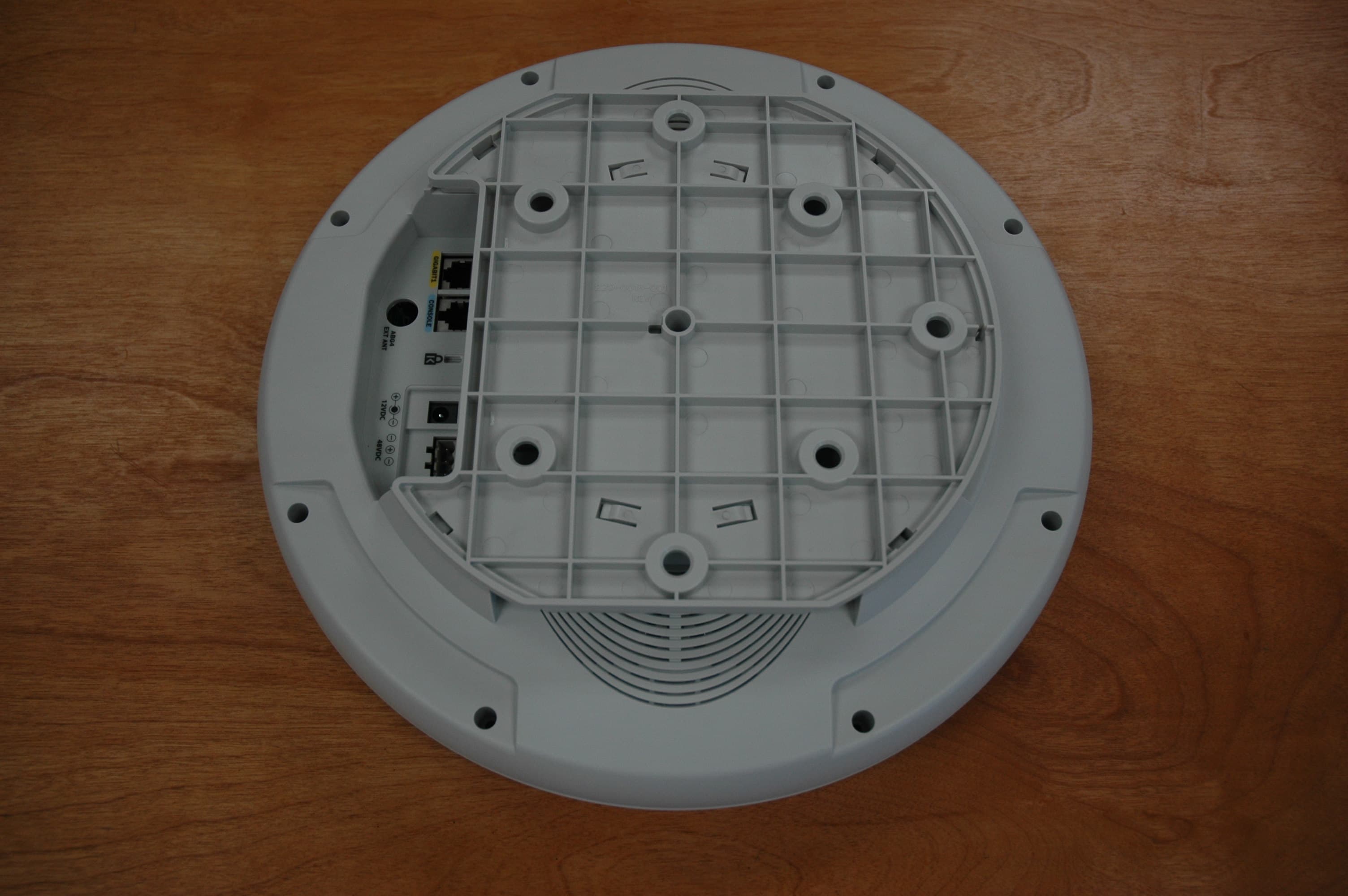
Click to zoom
Application Details
- Equipment Class
- DTS - Digital Transmission System
- Date of Grant
- Dec 06, 2005
- Application Purpose
- Original Equipment
- Date of Application
- Dec 06, 2005
- Equipment Note
- XS-3500 Wireless LAN Array
- Frequency Range
- 5745.00000000 - 5825.00000000
- Company
- Cambium Networks
- Country
- United States
Documents & Files
Document Text
Text extracted from the exhibit documents filed with the FCC. Open a document above to read the original.
Users Manual
XS 3900 3700 3500 WirelessWireless WirelessWireless Wireless LAN ArrayLAN Array LAN ArrayLAN Array LAN Array User’s Guide November 3rd, 2005 Copyright © 2005 Xirrus, Inc. 370 North Westlake Blvd, Suite 200 Westlake Village, CA 91362 USA www.xirrus.com All rights reserved. This document may not be reproduced or disclosed in whole or in part by any means without the written consent of Xirrus, Inc. Part Number: 800-0006-001 (Revision C) Wireless LAN Array XS-3900, XS-3700, XS-3500 Trademarks is a trademark of Xirrus, Inc. All other trademarks and brand names are marks of their respective holders. Notices FCC Notice This device complies with Part 15 of the FCC Rules, with operation subject to the following two conditions: (1) This device may not cause harmful interference, and (2) this device must accept any interference received, including interference that may cause unwanted operation. This equipment has been tested and found to comply with the limits for a Class A digital device, pursuant to Part 15 of the FCC rules. These limits are designed to provide reasonable protection against harmful interference in a residential installation. This equipment generates, uses and can radiate RF energy and, if not installed and used in accordance with the instructions, may cause harmful interference to radio communications. However, there is no guarantee that interference will not occur in a particular installation. If this equipment does cause harmful interference to radio or television reception, which can be determined by turning the equipment off and on, the user is encouraged to try to correct the interference by one or more of the following safety measures: zReorient or relocate the receiving antenna. zIncrease the separation between the equipment and the receiver. zConsult the dealer or an experienced wireless technician for help. Use of a shielded twisted pair (STP) cable must be used for all Ethernet connections in order to comply with EMC requirements. RF Radiation Hazard Warning To ensure compliance with FCC RF exposure requirements, this device must be installed in a location where the antennas of the device will have a minimum distance of at least 25 cm (9.84 inches) from all persons. Using higher gain antennas and types of antennas not certified for use with this product is not allowed. The device shall not be co-located with another transmitter. Non-Modification Statement Unauthorized changes or modifications to the device are not permitted. Use only the supplied internal antenna, or external antennas supplied by the manufacturer. Modifications to the device will void the warranty and may violate FCC regulations. Please go to the Xirrus Web site for a list of all approved antennas. Indoor Use This product has been designed for indoor use. Operation of channels in the 5150MHz to 5250MHz band is permitted indoors only to reduce the potential for harmful interference to co-channel mobile satellite systems. Maximum Antenna Gain Currently, the maximum antenna gain for external antennas is limited to 5.2dBi for operation in the 2400MHz to 2483.5MHz, 5250MHz to 5350MHz and 5725MHz to 5825MHz bands. The antenna gains must not exceed maximum EIRP limits set by the FCC / Industry Canada. High Power Radars High power radars are allocated as primary users (meaning they have priority) in the 5250MHz to 5350MHz and 5650MHz to 5850MHz bands. These radars could cause interference and/or damage to LELAN devices used in Canada. Industry Canada Notice and Marking This Class A digital apparatus complies with Canadian ICES-003. Cet appareil numérique de la classe A est conforme à la norme NMB-003 du Canada. The term “IC:” before the radio certification number only signifies that Industry Canada technical specifications were met. To reduce potential radio interference to other users, the antenna type and its gain should be so chosen that the equivalent isotropically radiated power (EIRP) is not more than that required for successful communication. EU Directive 1999/5/EC Compliance Information This section contains compliance information for the Xirrus Wireless LAN Array family of products, which includes the XS-3900, XS-3700 and XS-3500. The compliance information contained in this section is relevant to the European Union and other countries that have implemented the EU Directive 1999/5/EC. Declaration of Conformity Cesky [Czech]Toto zahzeni je v souladu se základnimi požadavky a ostatnimi odpovidajcimi ustano veni mi Sm ěrnice 1999/5/EC. Dansk [Danish]Dette udstyr er i overensstemmelse med de væsentlige krav og andre relevante bestemmelser i Direktiv 1999/5/EF. Deutsch [German]Dieses Gerat entspricht den grundlegenden Anforderungen und den weiteren entsprechenden Vorgaben der Richtinie 1999/5/EU. Eesti [Estonian]See seande vastab direktiivi 1999/5/EU olulistele nöuetele ja teistele as jakohastele sätetele. EnglishThis equipment is in compliance with the essential requirements and other relevant provisions of Directive 1999/5/EC. Español [Spain]Este equipo cump le con los requisitos esenciales asi como con otras disposiciones de la Directiva 1999/5/ CE. Ελληνυκη [Greek]Αυτόζ ο εξοπλτσμόζ είναι σε συμμόρφωση με τιζ ουσιώδειζ απαιτήσειζ και ύλλεζ σχετικέζ διατάξειζ τηζ Οδηγιαζ 1999/5/EC. Français [French]Cet appareil est conforme aux exigences essentielles et aux autres dispositions pertinentes de la Directive 1999/5/EC. ĺslenska [Icelandic] Þetta tæki er samkvæmt grunnkröfum og öðrum viðeigandi ákvæðum Tilskipunar 1999/5/EC. Italiano [Italian]Questo apparato é conforme ai requisiti essenziali ed agli altri principi sanciti dalla Direttiva 1999/5/CE. Latviski [Latvian]Šī iekārta atbilst Direktīvas 1999/5/EK būtiskajā prasībām un citiem ar to saistītajiem noteikumiem. Lietuvių [Lithuanian]Šis įrenginys tenkina 1995/5/EB Direktyvos esminius reikalavimus ir kitas šios direktyvos nuostatas. Nederlands [Dutch]Dit apparant voldoet aan de essentiele eisen en andere van toepassing zijnde bepalingen van de Richtlijn 1…
Text truncated - open the document above for the full version.
Users Manual
Wireless LAN Array Introduction19 SecurityWireless Security: WEP 40bit/128bit encryption WPA with TKIP and AES encryption Misappropriated APs automatically reset to factory defaults (requires the Xirrus Wireless Management System) Rogue AP detection, with alerts and classification User and System Authentication: WPA Pre-Shared Key authentication Embedded RADIUS Server 802.1x EAP-TLS 802.1x EAP-TTLS 802.1x PEAP External RADIUS servers Authentication of Xirrus Arrays to the Xirrus Management System (XM-3300) ElementSpecifications Wireless LAN Array 20Introduction WirelessNumber of Radios: 4 x 802.11a/b/g radios Wireless Standards: 802.11a/b/g and g-only mode 802.11e (draft), 802.11i Channel Selection: Manual Automatic Frequency Bands: 11a: 5.15-5.25 GHz (UNII 1) 11a: 5.15-5.25 GHz (TELEC) 11a: 5.25-5.35 GHz (UNII 2) 11a: 5.470-5.725 (ETSI) 11a: 5.725-5825 GHz (UNII 3) 11b/g: 2.412-2.462 GHz (FCC) 11b/g: 2.412-2.472 GHz (ETSI) 11b/g: 2.412-2.484 GHz (TELEC) Antenna: 4 internal 3 dBi 180° 802.11b/g sectorized antennas 1 internal 2 dBi 360° omni-directional antenna External RP-TNC connector Radio Approvals: FCC (United States) EN 301.893 (Europe) ComplianceUL / cUL 60950 and EN 60950 FCC Part 15.107 and 15109, Class A EN 301.489 (Europe) WarrantyOne year (hardware), 90 day (software) ElementSpecifications Wireless LAN Array Installing the Xirrus Array21 Installing the Xirrus Array This chapter defines the prerequisites for installing the Xirrus Array and provides instructions to help you complete a successful installation. Section headings for this chapter include: z“Installation Prerequisites” on page 21 z“Planning Your Installation” on page 24 z“Installation Workflow” on page 39 z“Unpacking the Xirrus Array” on page 40 z“Installing Your Xirrus Wireless LAN Array” on page 41 z“Powering Up the Xirrus Wireless LAN Array” on page 51 z“Establishing Communication with the Array” on page 53 z“Performing the Express Setup Procedure” on page 54 Installation Prerequisites Your Xirrus Array deployment requires the presence of hardware and services in the host wired/wireless network, including: zDedicated AC power outlet Unless you are using the Xirrus Remote DC Power System (XP-3100) with the DC version of the Xirrus Array, you need a dedicated power outlet to supply AC power to each unit deployed at the site. If you are using the optional XP-3100, then DC power is supplied to all units and only one AC outlet is required for the XP-3100. zEthernet port (read notes) You need at least one 10/100/1000 BaseT port to establish wired Gigabit Ethernet connectivity (via the product’s Gigabit 1 or Gigabit 2 port) and one 10/100 BaseT port (if desired) for product management. ! The Array’s Ethernet ports should be plugged into an Ethernet switch, not an Ethernet hub—if a hub is used, we recommend that you connect only one Ethernet port. Wireless LAN Array 22Installing the Xirrus Array zSecure Shell (SSH) utility To establish secure remote command line access to the Array, you need a Secure Shell (SSH) utility, such as PuTTY. zSecure Web browser Either Internet Explorer (version 6.0 or higher), Netscape Navigator (version 7.0 or higher), or Mozilla Firefox (version 1.01 or higher) and it must be available on the same subnet as the Array. A secure Web browser is required for Web-based management of the Array. zSerial connection capability To connect directly to the console port on the Array, your computer must be equipped with a male 9-pin serial port and terminal emulation software (for example, HyperTerminal). Use the following settings when establishing a serial connection: ! The Gigabit1 Ethernet interface is the primary port for both data and management traffic. If a single Ethernet connection is used, it must be connected to the Gigabit1 Ethernet interface. The 10/100 Ethernet Port can be used for managing the Array, and will only bridge management traffic. See also, “Port Failover Protection” on page 33. Bits per second115,200 Data bits8 ParityNone Stop bits1 Flow controlNone Wireless LAN Array Installing the Xirrus Array23 Optional Network Components The following network components are optional. zDHCP server To distribute IP addresses and ancillary information to your Xirrus Array. zXirrus Wireless Management System (XM-3300) The optional XM-3300 offers powerful management features for small or large Xirrus Array deployments. zXirrus Remote DC Power System (XP-3100) The optional XP-3100 provides distributed DC power to multiple Arrays, eliminating the need to run dedicated AC power to each unit and facilitating backup power when connected via a UPS. zExternal RADIUS server Although your Array comes with an embedded RADIUS server, for 802.1x authentication in large deployments you may want to add an external RADIUS server. Client Requirements The Xirrus Array should only be used with Wi-Fi certified client devices. Wireless LAN Array 24Installing the Xirrus Array Planning Your Installation This section provides guidelines and examples to help you plan your Xirrus Array deployment to achieve the best overall coverage and performance. We recommend you conduct a site survey to determine the best location and settings for each Array you install. General Deployment Considerations The Xirrus Array’s unique multi-radio architecture generates 360 degrees of sectored high-gain 802.11a/b/g coverage that provides extended range. However, the number, thickness and location of walls, ceilings or other objects that the wireless signals must pass through may affect the range. Typical ranges vary depending on the types of materials and background RF (radio frequency) noise at your location. To maximize wireless range, follow these basic guidelines: 1.Keep the number of walls and ceilings between the Array and your receiving devices to a minimum—each wall or ceiling can reduce the wireless range from between 3 and 90 feet (1 to 30 meters). Position your devices so that the number of walls or ceilings is minimized. 2.Be aw…
Text truncated - open the document above for the full version.
Users Manual
Wireless LAN Array Configuring the Xirrus Array69 Configuring the Xirrus Array This chapter covers configuration and management tasks using the product’s embedded Web Management Interface (WMI). It also includes a procedure for logging in to the XS-3900/XS-3700/XS-3500 with your Web browser. Section headings for this chapter include: z“Logging In” on page 69 z“Making Configuration Changes to the Array” on page 70 Logging In Use this procedure to log in to the WMI via your Web browser. 1.Establish a network connection and open your Web browser. 2.Connect to the Wireless LAN Array via its default IP address (10.0.1.1) or via a DHCP assigned IP address. 3.When connected to the Array, a login prompt appears on your screen. The default login for the user name and password is admin for both. Login names and passwords are case-sensitive. 4.To log in to the Array’s Web Management Interface, enter admin when prompted for a user name and password. Figure 46. WMI: Logging In to the Wireless LAN Array Wireless LAN Array 70Configuring the Xirrus Array Making Configuration Changes to the Array This section has been organized into functional areas that reflect the flow and content of the WMI. Configuration instructions to the Wireless LAN Array require you to input data in one or more of the following formats: zSpecifying data (for example, IP addresses, descriptions, etc.). zMaking selections from pull-down lists. zChoosing an option by clicking on a radio button (for example, on/off). zClicking on a check box to activate/deactivate a feature. zClicking on a button to confirm a command or apply your changes. Array Status This is a status only page that provides a snapshot of the global configuration settings for all XS-3900/XS-3700/XS-3500 network interfaces and radios. You must go to the appropriate configuration page to make changes to any of the settings displayed here (configuration changes cannot be made from this page). Figure 47. WMI: Array Status Page Wireless LAN Array Configuring the Xirrus Array71 The Array Status page is sub-divided into the Network Interface and IAP Interface (radio) sections and provides you with the following information: zAll devices: A listing of the available Network Interfaces and IAPs with each item containing a link to the associated configuration page. Linked items are shown UNDERLINED . For example: Figure 48. Linked Items zAll devices: The current status of each device, whether enabled or disabled. Devices that are disabled are shown in RED. For example: Figure 49. WMI: Disabled Device (Partial View) zNetwork Interface devices: zThe Management column indicates whether the network interface device is enabled or disabled. Network interfaces are enabled or disabled on the Network Settings page. zThe Configuration column shows how each network interface obtains its IP address—either dynamically via DHCP or entered manually by you (static configuration) on the Network Settings page. These items are linked Disabled devices are shown in RED Wireless LAN Array 72Configuring the Xirrus Array zThe IP Address column shows the current IP address being used by each network interface device. zIAP Interface devices: zThe Channel column shows on which channel each IAP (radio) is operating. Channel selections are made on the IAP Settings page from a pull-menu. To avoid co-channel interference, adjacent radios should not be using adjacent channels. zThe Cell Size column indicates which cell size setting is currently active for each radio—either small, medium, large or manually defined by you. The cell size of a radio is a function of its transmit power and determines the radio’s overall coverage. Cell sizes are defined on the IAP Settings page. For additional information about cell sizes and the importance of planning for and defining the optimum sizes for your Array, go to “Coverage and Capacity Planning” on page 25. Figure 50. IAP Cells zThe Associated Users column informs you how many users are currently associated with each radio. The high-capacity XS-3900 can handle up to 64 concurrent users per individual IAP radio (1024 or 960 users per Array when the monitor is enabled). Wireless LAN Array Configuring the Xirrus Array73 Express Setup This page allows you to establish global configuration settings that will enable basic Array functionality. Any changes you make on this page will affect all radios. When finished, click on the Apply button to apply the new settings to this session, then click on the Save button to save your changes. Figure 51. WMI: Express Setup Page (Part 1) more ... Wireless LAN Array 74Configuring the Xirrus Array Figure 52. WMI: Express Setup Page (Part 2) Procedure for Performing an Express Setup 1.Host Name: Specify a unique host name for this Array. The host name is used to identify the Array on the network. Use a name that will be meaningful within your network environment, up to 64 alphanumeric characters. 2.Location Information: Enter a brief but meaningful description that accurately defines the physical location of the Array. In an environment where multiple units are installed, clear definitions for their locations are important if you want to identify a specific unit. 3.Admin Contact: Enter the name and contact information of the person who is responsible for administering the Array at the designated location. 4.Admin Email: Enter the email address of the admin contact you entered in Step 3. 5.Admin Phone: Enter the telephone number of the admin contact you entered in Step 3. 6.Enable/Configure All IAPs: Click on the Execute button to enable and auto configure all IAPs (a message displays the countdown time—in seconds—to complete the auto-configuration task). ... continued Wireless LAN Array Configuring the Xirrus Array75 7.Configure the Fast Ethernet (10/100 Megabit), Gigabit 1 and Gigabit 2 network interfaces. The fields for each of these interfaces are the same, and include: a.Enable Interface: Choose Ye s to enable this network interface, …
Text truncated - open the document above for the full version.
Users Manual
Wireless LAN Array Configuring the Xirrus Array119 Procedure for Configuring Radius Servers 1.Radius Server Mode: Choose Internal if you want to use the XS-3900’s internal RADIUS server, or choose External to use an external RADIUS server. 2.Primary IP Address: If you are using an external RADIUS server, enter the primary server ’s IP address. 3.Primary Port Number: If you are using an external RADIUS server, enter the primary port number. 4.Secondary IP Address (optional): If desired, enter the secondary RADIUS server’s IP address. If the primary RADIUS server becomes off-line, the Array will “failover” to the secondary RADIUS server (defined here). 5.Secondary Port Number: If desired, enter the secondary port number. 6.Timeout: Define the maximum idle time (in seconds) before the RADIUS session times out. The default is 600 seconds. 7.Primary Shared Secret / Verify Secret: If you are using RADIUS, enter the primary shared secret, then re-enter the primary shared secret to verify that you typed it correctly. 8.Secondary Shared Secret / Verify Secret: If you are using RADIUS, enter the secondary shared secret, then re-enter the secondary shared secret to verify that you typed it correctly. 9.Click on the Apply button to apply the new settings to this session. 10.Click on the Save button to save your changes (otherwise your new settings will not take effect). Wireless LAN Array 120Configuring the Xirrus Array Radius User This page allows you to manage local RADIUS user accounts (create, modify and delete). When finished, click on the Save button to save your changes. Figure 79. WMI: Radius User Page Wireless LAN Array Configuring the Xirrus Array121 Procedure for Configuring Radius Users 1.New User Name: Enter a new RADIUS user name. 2.User Password: Enter a password for this user. 3.Verify Password: Re-enter the user password to verify that you typed it correctly. 4.SSID (Network Name): Choose an SSID from the pull-down list (this will be the only SSID a user can associate to). 5.Click on the Create User button to add this user to the list. Editing Radius Users 6.User Management: If you want to edit an existing RADIUS user account, select the user from the list. You must now enter the user password and select an SSID. a.User Password: Enter the password of the user account you want to edit. b.Verify Password: Re-enter the password to verify that you typed it correctly. c.SSID (Network Name): Choose an SSID from the pull-down list. When you have finished making your edits, click on the Modify button to apply the changes. 7.Alternatively, you can delete users by selecting the user from the list and clicking on the Delete button. 8.Click on the Save button to save your changes (otherwise your new settings will not take effect). Wireless LAN Array 122Configuring the Xirrus Array MAC Access List This page allows you to create new MAC access lists, delete existing lists, and add/remove MAC addresses. When finished, click on the Save button to save your changes. Figure 80. WMI: MAC Access List Page Wireless LAN Array Configuring the Xirrus Array123 Procedure for Configuring MAC Access Lists 1.MAC Access List Type: Select the MAC Access List type—either Disabled, Allow List or Deny List, then click on the Modify button to apply your changes. zAllow List: Only allows these MAC addresses to associate to the Array. zDeny List: Allows all MAC addresses except the addresses defined in this list. 2.New MAC Address: If you want to add a MAC address to the ACL, enter the new MAC address here, then click on the Add button. The MAC address is added to the ACL. 3.MAC Access List Management: You can delete a MAC Access List by selecting the list you want to delete then clicking on the Delete button. 4.Click on the Save button to save your changes (otherwise your new settings will not take effect). # In addition to these lists, other authentication methods (for example, RADIUS) are still enforced for users. Wireless LAN Array 124Configuring the Xirrus Array Admin Management This page allows you to manage network administrator accounts (create, modify and delete). It also allows you to limit account access to a read only status. When finished, click on the Save button to save your changes. Figure 81. WMI: Admin Management Page Wireless LAN Array Configuring the Xirrus Array125 Procedure for Creating Network Administrator Accounts 1.New Admin ID: Enter a meaningful description for this new network administrator ID. 2.Privilege Level: Choose Read to restrict this administrator ID to read only status, or choose Read/Write if you want to give this administrator ID full read/write privileges. In the read only mode, administrators cannot save changes to configurations. 3.Admin Password: Enter a password for this ID. 4.Verify Password: Re-enter the password in this field to verify that you typed the password correctly. If you do not re-enter the correct password, an error message is displayed). 5.Click on the Create button to add this administrator ID to the list. Editing Network Administrator Accounts 6.Admin ID: Choose the administrator ID you want to edit or delete from the list. If you are deleting the selecting administrator ID, click on the Delete button, otherwise go to Step 7. 7.Privilege Level: Choose Read to restrict the selected administrator ID to read only status, or choose Read/Write if you want to give this administrator ID full privileges. 8.Admin Password: Enter the password for the selected administrator ID. 9.Verify Password: Re-enter the password in the right field (this field must match the Admin Password field). 10.Click on the Modify button to apply the new settings to this session. 11.Click on the Save button to save your changes (otherwise your new settings will not take effect). Wireless LAN Array 126Configuring the Xirrus Array Rogue AP List This page displays rogue APs, according to the list you select (either Unknown, Known or Approved). In addition, you can sort the results based on the…
Text truncated - open the document above for the full version.
Users Manual
Wireless LAN Array The Command Line Interface169 USAGE GUIDELINES Setting Gigabit2 Interface parameters will automatically set the Gigabit1 parameters to the same values for failover purposes. EXAMPLE To set the IP address of the gigabit Ethernet interfaces: config-interface gig2 ((config-gig1/2)# ip addr 192.168.39.186 mask 255.255.255.0 Figure 101. CLI: Setting the IP Address for the Gigabit 2 Interface SEE ALSO config-interface gig1 config-interface eth0 Wireless LAN Array 170The Command Line Interface hostname DESCRIPTION Sets the host name for this Array—available from the config command mode. SYNTAX hostname <hname> “hostname string” PARAMETERS None. DEFAULTS None. USAGE GUIDELINES None. EXAMPLE To set the hostname for the Xirrus Array: (config)# hostname Xirrus_Array_3900 Figure 102. CLI: Setting the Host Name of the Array The hostname is displayed immediately below the command line, as follows: Xirrus_Array_3900(config)# Wireless LAN Array The Command Line Interface171 SEE ALSO None. iap DESCRIPTION Changes the configuration of a specific Integrated Access Point (IAP) radio interface—available from the config-interface command mode. Groups of interfaces can be accessed via the following interface commands. ziap number: Configuration for a specific IAP. The prompt will change to: IAP number (config-iap-a12)#. zglobal_a_settings: Common configuration for all 802.11a IAPs. The prompt will change to: (config-iap-global-a)#. zglobal_bg_settings: Common configuration for all 802.11b/g IAPs. The prompt will change to: (config-iap-global-bg)#. zglobal_settings: Common configuration for all IAPs. The prompt will change to: (config-iap-global)#. SYNTAX interface iap <IAP number> {channel <cnum> | description <dot11desc> | down | up | cellsize {small | medium | large} | rx-threshold <thresrx> | tx-power <powertx>} } PARAMETERS cellsizeCell size setting channelChannel number descriptionName to identify this IAP (up to 32 characters) downShut down (disable) this IAP rx-thresholdDeferred threshold (receive sensitivity) tx-power Maximum transmit power upBring up (enable) this IAP dot11aSet 802.11a mode dot11bgSet 802.11b/g mode (only available on abg1, 2, 3, 4) antennaSelect the antenna for the IAP internalInternal directional 2.4GHz antenna Wireless LAN Array 172The Command Line Interface monitorInternal omni-directional monitor antenna (available on abg2 IAP only) externalSelect the external antenna (Available on IAP abg1, abg3, and abg4 only) DEFAULTS None. USAGE GUIDELINES None. EXAMPLE To set the cell size to large for the integrated access point a12: (config-iap)# a12 (config-iap-a12)# cellsize large Figure 103. CLI: Setting the Cell Size of an IAP SEE ALSO iap global_a_settings iap global_bg_settings iap global_settings show iap all Wireless LAN Array The Command Line Interface173 iap global_settings DESCRIPTION Makes global configuration changes to all Integrated Access Point (IAP) radio interfaces—available from the config-interface command mode. This command allows configuration changes to all IAP interfaces. Other global settings can be made for specific groups of IAPs by using one of the below parameters in the interface IAP command mode: ziap number: Configuration for a specific IAP. The prompt will change to: IAP number (config-iap-a12)# zglobal_a_settings: Common configuration for all 802.11a IAPs. The prompt will change to: (config-iap-global-a)# zglobal_bg_settings: Common configuration for all 802.11b/g IAPs. The prompt will change to: (config-iap-global-bg)# zglobal_settings: Common configuration for all IAPs. The prompt will change to: (config-iap-global)# SYNTAX iap global_settings {all_down | all_up | [no] rogue_detect [ on | off | add <ssa> {approved | known} | del <ssd> | list ] | auto_channel [no][power_up [ on | off ] | schedule [<ts>]] | long-retries <lrl> | short- retries <srl> | cellsize {small | medium | large} | rx-threshold <thresrx> | tx-power <powertx> | beacon-rate <brate> | beacon-dtim <bdtim> | inactive-time <at> | reauth-period <ht> | led {disable | enable {iap_up | associated}} | led_activity {beacon | tx_data | rx_data | tx_mgmt | rx_mgmt | broadcast | probe_req | assoc}} PARAMETERS ledEnable or disable the IAP leds disableDo not turn IAP leds on enableTurn an IAP led on when up (default) or when a station is associated iap_upTurn an IAP led on when the IAP is up associatedTurn an IAP led on when at least one station is associated with it Wireless LAN Array 174The Command Line Interface led_activitySet IAP led behavior based on certain conditions beaconBlink an IAP led when a beacon is transmitted tx_dataBlink an IAP led when a data frame is transmitted rx_dataBlink an IAP led when a data frame is received tx_mgmtBlink an IAP led when a management frame is transmitted rx_mgmtBlink an IAP led when a management frame is received broadcastBlink an IAP led when a broadcast frame is transmitted probe_reqBlink an IAP led when a probe request is received assocBlink an IAP led heartbeat when stations are associated beacon-rateTime between beacons in kilo-microseconds (Kusec) beacon-dtimBeacons between Delivery Traffic Indication Messages (DTIM) all_downShut down (disable) all IAPs all_upBring up (enable) all IAPs short-retriesShort retry limit long-retriesLong retry limit inactive-timeTime that an AP tracks an inactive station reauth-periodTime between 802.1x re-authentication attempts rogue_detectEnable/disable rogue AP detection on IAP abg2 onEnable rogue AP detection offDisable rogue AP detection addAdd SSID to rogue database delDelete SSID from rogue database approvedMark SSID as approved (stop reporting and displaying) knownMark SSID as known (stop reporting but display with an *) listList rogue database cellsizeCell size setting smallSmall cell size mediumMedium cell size largeLarge cell size rx-thresholdDeferred threshold tx-powerMaximum transmit power Wireless LAN Array The Command Line Interface175 auto_channelAutomatically assign channels to all IAPs po…
Text truncated - open the document above for the full version.
Contact Information
Applicant
Steven M Payne(Principal Staff Engineer - RF)
Technical Contact
Elliott Laboratories Inc.Mark Briggs
[email protected]408-245-7800
684 West Maude Ave. · Sunnyvale, California · United States
Non-Technical Contact
Elliott Laboratories Inc.Mark Briggs
[email protected]408-245-7800
Test Firm
Elliott Laboratories LLCDavid Bare
Technical Specifications
| # | Rule Parts | Frequency Range | Power Output |
|---|---|---|---|
| 2 | 15C | 5.75 GHz - 5.83 GHz | 126.00 mW |
Other Applications from Cambium Networks

SK6-XH2120
Sep 23, 2015Hardened Wireless Access Point
Equipment Class
DTS - Digital Transmission System
SK6-X2120
Sep 08, 2015Wireless Access Point
Equipment Class
DTS - Digital Transmission System
SK6-XDR130
Jun 02, 2015Wireless Access Point Radio module
Equipment Class
NII - Unlicensed National Information Infrastructure TX
SK6-XR320
Nov 24, 2014Wireless Access Point
Equipment Class
NII - Unlicensed National Information Infrastructure TX
SK6-XI-AC867
Jun 08, 2014Wireless Access Point
Equipment Class
NII - Unlicensed National Information Infrastructure TX