SK6XS3700AXS-3700 Wireless LAN Array
Cambium Networks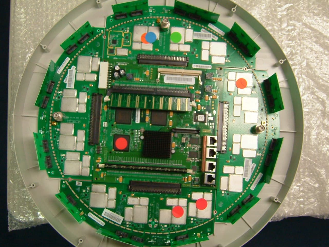
Click to zoom
Application Details
- Equipment Class
- NII - Unlicensed National Information Infrastructure TX
- Date of Grant
- Apr 19, 2006
- Application Purpose
- Original Equipment
- Date of Application
- Apr 19, 2006
- Equipment Note
- XS-3700 Wireless LAN Array
- Frequency Range
- 5260.00000000 - 5320.00000000
- Company
- Cambium Networks
- Country
- United States
Documents & Files
Document Text
Text extracted from the exhibit documents filed with the FCC. Open a document above to read the original.
Users Manual
XS 3900 3700 3500 WirelessWireless WirelessWireless Wireless LAN ArrayLAN Array LAN ArrayLAN Array LAN Array User’s Guide March 17th, 2006 All rights reserved. This document may not be reproduced or disclosed in whole or in part by any means without the written consent of Xirrus, Inc. Part Number: 800-0006-001 (Revision E) Wireless LAN Array XS-3900, XS-3700, XS-3500 Trademarks is a trademark of Xirrus, Inc. All other trademarks and brand names are marks of their respective holders. Notices FCC Notice This device complies with Part 15 of the FCC Rules, with operation subject to the following two conditions: (1) This device may not cause harmful interference, and (2) this device must accept any interference received, including interference that may cause unwanted operation. This equipment has been tested and found to comply with the limits for a Class A digital device, pursuant to Part 15 of the FCC rules. These limits are designed to provide reasonable protection against harmful interference in a residential installation. This equipment generates, uses and can radiate RF energy and, if not installed and used in accordance with the instructions, may cause harmful interference to radio communications. However, there is no guarantee that interference will not occur in a particular installation. If this equipment does cause harmful interference to radio or television reception, which can be determined by turning the equipment off and on, the user is encouraged to try to correct the interference by one or more of the following safety measures: zReorient or relocate the receiving antenna. zIncrease the separation between the equipment and the receiver. zConsult the dealer or an experienced wireless technician for help. Use of a shielded twisted pair (STP) cable must be used for all Ethernet connections in order to comply with EMC requirements. RF Radiation Hazard Warning To ensure compliance with FCC RF exposure requirements, this device must be installed in a location where the antennas of the device will have a minimum distance of at least 25 cm (9.84 inches) from all persons. Using higher gain antennas and types of antennas not certified for use with this product is not allowed. The device shall not be co-located with another transmitter. Non-Modification Statement Unauthorized changes or modifications to the device are not permitted. Use only the supplied internal antenna, or external antennas supplied by the manufacturer. Modifications to the device will void the warranty and may violate FCC regulations. Please go to the Xirrus Web site for a list of all approved antennas. Indoor Use This product has been designed for indoor use. Operation of channels in the 5150MHz to 5250MHz band is permitted indoors only to reduce the potential for harmful interference to co-channel mobile satellite systems. Maximum Antenna Gain Currently, the maximum antenna gain for external antennas is limited to 5.2dBi for operation in the 2400MHz to 2483.5MHz, 5150MHz to 5250MHz and 5725MHz to 5825MHz bands. The antenna gains must not exceed maximum EIRP limits set by the FCC / Industry Canada. High Power Radars High power radars are allocated as primary users (meaning they have priority) in the 5150MHz to 5250MHz and 5650MHz to 5850MHz bands. These radars could cause interference and/or damage to LELAN devices used in Canada. Industry Canada Notice and Marking This Class A digital apparatus complies with Canadian ICES-003. Cet appareil numérique de la classe A est conforme à la norme NMB-003 du Canada. The term “IC:” before the radio certification number only signifies that Industry Canada technical specifications were met. To reduce potential radio interference to other users, the antenna type and its gain should be so chosen that the equivalent isotropically radiated power (EIRP) is not more than that required for successful communication. EU Directive 1999/5/EC Compliance Information This section contains compliance information for the Xirrus Wireless LAN Array family of products, which includes the XS-3900, XS-3700 and XS-3500. The compliance information contained in this section is relevant to the European Union and other countries that have implemented the EU Directive 1999/5/EC. Declaration of Conformity Cesky [Czech]Toto zahzeni je v souladu se základnimi požadavky a ostatnimi odpovidajcimi ustano veni mi Sm Črnice 1999/5/EC. Dansk [Danish]Dette udstyr er i overensstemmelse med de væsentlige krav og andre relevante bestemmelser i Direktiv 1999/5/EF. Deutsch [German]Dieses Gerat entspricht den grundlegenden Anforderungen und den weiteren entsprechenden Vorgaben der Richtinie 1999/5/EU. Eesti [Estonian]See seande vastab direktiivi 1999/5/EU olulistele nöuetele ja teistele as jakohastele sätetele. EnglishThis equipment is in compliance with the essential requirements and other relevant provisions of Directive 1999/5/EC. Español [Spain]Este equipo cump le con los requisitos esenciales asi como con otras disposiciones de la Directiva 1999/5/ CE. ǼȜȜȘȞȣțȘ [Greek]ǹȣIJȩȗ Ƞ İȟȠʌȜIJıμȩȗ İȓȞĮȚ ıİ ıȣμμȩȡijȦıȘ μİIJȚȗ ȠȣıȚȫįİȚȗ ĮʌĮȚIJȒıİȚȗ țĮȚ ȪȜȜİȗ ıȤİIJȚțȑȗ įȚĮIJȐȟİȚȗ IJȘȗ ȅįȘȖȚĮȗ 1999/5/EC. Français [French]Cet appareil est conforme aux exigences essentielles et aux autres dispositions pertinentes de la Directive 1999/5/EC. Ďslenska [Icelandic] Þetta tæki er samkvæmt grunnkröfum og öðrum viðeigandi ákvæðum Tilskipunar 1999/5/EC. Italiano [Italian]Questo apparato é conforme ai requisiti essenziali ed agli altri principi sanciti dalla Direttiva 1999/5/CE. Latviski [Latvian]ŠƯiekƗrta atbilst DirektƯvas 1999/5/EK bnjtiskajƗ prasƯbƗm un citiem ar to saistƯtajiem noteikumiem. Lietuviǐ [Lithuanian]Šis Ƴrenginys tenkina 1995/5/EB Direktyvos esminius reikalavimus ir kitas šios direktyvos nuostatas. Nederlands [Dutch]Dit apparant voldoet aan de essentiele eisen en andere van toepassing zijnde bepalingen van de Richtlijn 1995/5/EC. Malti [Maltese]Dan l-apparant huwa konformi mal-htigiet essenzjali u l-provedimenti l-o hra rile…
Text truncated - open the document above for the full version.
Users Manual
Wireless LAN Array 106Configuring the Xirrus Array Statistics (for all radios) This page provides a detailed statistical summary of the performance of all radios, displayed either numerically or by percentage (your choice). The following image shows an example from the XS-3700 product. The default Statistics Type is NUMERIC, but you can change this to PERCENTAGE from the pull-down menu at the top of the page. In addition, you canRefresh or Clear the data on this page at any time by clicking on the appropriate button. Figure 74. WMI: Statistics for All IAPs Page (XS-3700) Wireless LAN Array Configuring the Xirrus Array107 SSID This is a status only page that allows you to review SSID (Service Set IDentifier) assignments. It includes the SSID name, whether or not an SSID is visible on the network, any security and QoS parameters defined for each SSID, associated VLAN IDs, and radio availability per SSID. There are no configuration options available on this page, but if you are experiencing problems or reviewing SSID management parameters, you may want to print this page for your records. For information to help you understand SSIDs and how multiple SSIDs are managed by the XS-3900, go to the Multiple SSIDs section of “Frequently Asked Questions” on page 222. Figure 75. WMI: SSID Page Wireless LAN Array 108Configuring the Xirrus Array Understanding SSIDs The SSID (Service Set Identifier) is a unique identifier that wireless networking devices use to establish and maintain wireless connectivity. Multiple access points on a network or sub-network can use the same SSIDs. SSIDs are case-sensitive and can contain up to 32 alphanumeric characters (do not include spaces when defining SSIDs). Multiple SSIDs A BSSID (Basic SSID) refers to an individual access point radio and its associated clients. The identifier is the MAC address of the access point radio that forms the BSS. A group of BSSs can be formed to allow stations in one BSS to communicate to stations in another BSS by way of a backbone that interconnects each access point. The Extended Service Set (ESS) refers to the group of BSSIDs that are grouped together to form one ESS. The ESSID (often referred to as SSID or “wireless network name”) identifies the Extended Service Set. Clients must associate to a single ESS at any given time. Clients ignore traffic from other Extended Service Sets that do not have the same SSID. Legacy access points typically support one SSID per access point. Xirrus Wireless LAN Arrays support the ability for multiple SSIDs to be defined and used simultaneously. Using SSIDs The creation of different wireless network names allows system administrators to separate types of users with different requirements. The following policies can be tied to an SSID: zThe wireless security mode needed to join this SSID. zThe wireless Quality of Service (QoS) desired for this SSID. zThe wired VLAN associated with this SSID. Wireless LAN Array Configuring the Xirrus Array109 As an example, one SSID named accounting might require the highest level of security, while another SSID named guests might have low security requirements. Another example may define an SSID named voice that supports voice over Wireless LAN phones with the highest possible Quality of Service (QoS) definition. This type of SSID might also forward traffic to specific VLANs on the wired network. SSID Management This page allows you to manage SSIDs (create, edit and delete), and assign security parameters and VLANs on a per SSID basis. When finished, click on the Save button to save your changes, otherwise your changes will not take effect. Figure 76. WMI: SSID Management Page Wireless LAN Array 110Configuring the Xirrus Array Procedure for Managing SSIDs 1.New SSID: Enter a new SSID definition. 2.Security: From the pull-down list, choose the security that will be required by users for this SSID, either Open, WEP or WPA. The Open option provides no security and is not recommended. For an overview of the security options, go to “Security Planning” on page 35. 3.Qos Priority: From the pull-down list, select a Quality of Service (QoS) setting. The QoS setting you define here will prioritize wireless traffic for this SSID over other SSID wireless traffic. This step is optional. 4.VLAN ID: From the pull-down list, select a VLAN that you want this traffic to be forwarded to on the wired network. This step is optional. 5.Band Association: The Array allows you to choose which wireless band the SSID will be beaconed on. Select either 802.11a,802.11b/g or Both. 6.Click on the Create button to create this SSID. The SSID you just created will appear in the SSID List below. Editing SSIDs 7.SSID: Choose the SSID that you want to edit or delete from the list. If you are deleting a selected SSID, click on the Delete SSID button, otherwise go to Step 2. 8.Broadcast SSID: Click on the Enable button to make the selected SSID visible to all clients on the network. Although the XS-3900 will not broadcast SSIDs that are hidden, clients can still associate to a hidden SSID if they know the SSID name to connect to it. Choose Disable if you do not want this SSID to be visible on the network. Wireless LAN Array Configuring the Xirrus Array111 9.Security: From the pull-down list, choose the security that will be required by users for the selected SSID— either Open, WEP or WPA. The Open option provides no security and is not recommended. For an overview of the security options, go to “Security Planning” on page 35. 10.QoS Priority: From the pull-down list, select a Quality of Service (QoS) setting. The QoS setting you define here will prioritize wireless traffic for the selected SSID over other SSID wireless traffic. This step is optional. 11.VLAN ID: From the pull-down list, select a VLAN that you want this traffic to be forwarded to on the wired network. This step is optional. 12.Band Association: The Array allows you to choose which wireless band to associate with each SSID. Select either 8…
Text truncated - open the document above for the full version.
Cover Letter(s)
April 12, 2006 RE: Xirrus, Inc. FCC ID: SK6XS3700A 1) Please update the IC Form to remove the patch antenna. Uploaded ATCB-Appendix I and II form RSP-100 (8TRx) rev 3.doc 2) Please updated external photographs for both applications to remove the patch antenna shown in one of the photos. Uploaded External Photos rev2.pdf 3) Overall internal view shows all radios (16 version)....Please document with appropriate notes or correct the photograph. Uploaded Whole Unit no top rev1.pdf 4) RF boards for the schematics are labeled dual, but appear to contain all 4 radios. Please review/correct. Uploaded 130-0038revised.pdf 5) Are AC powerline test photos available. If so, please provide. Uploaded AC CE Test Configuration Photographs.pdf 6) Please provide the last corrected manual applicable to this device as modified for the other similar application. The manual provided appears to be the older version. Uploaded xirrus_array_userguide2-1.pdf and xirrus_array_userguide2-2.pdf Regards, Mark Briggs Principal Engineer
ID Label/Location Info
4 1 3 1 2 1 3 5 5 1 4 4 2 3 5 I.LAITYC. LEONARD2/2/2005 INITIAL RELEASEA APPROVEDBYDATEDESCRIPTIONREV. ITEM NO. PART NO. DESCRIPTION QTY 6830-0014-001 XS3900,LABEL, ALIGNMENT INDICATOR 4 5 830-0013-001 XS3900,LABEL, BRACKET REMOVAL 1 4830-0002-002 LABEL PRODUCT, XS3900-8 1 3 170-0001-002 TLA,XS3900-8, UNLABELED 1 2220-0001-001 BRACKET, MOUNTING 1 1830-0006-001 EMBLEM, 1.5, XS3900 1 REVISIONS ZONE DO NOT OVERLAP TOP OR BOTTOM EDGE OF BRACKET. NOTES: 1. SPLIT BALLOONS CONTAIN ITEM NUMBER IN THE TOP PORTION AND QUANTITY IN THE BOTTOM PORTION. ALIGN TAB ON EMBLEM WITH SLOT IN EMBLEM RECESS. CENTER EMBLEM WITHIN CIRCULAR EMBLEM RECESS. PRODUCT LABEL AND ALIGNMENT LABELS MUST BE INSTALLED PRIOR TO INSTALLING BRACKET ONTO UNIT. CENTER ALIGNMENT INDICATOR LABEL BETWEEN TWO VERTICAL RIBS ON BRACKET, DO NOT OVERLAP TOP OR BOTTOM EDGE OF BRACKET. BRACKET REMOVAL LABEL ARROW MUST BE ALIGNED WITH RIB AS SHOWN. ALIGN BRACKET AS SHOWN AND TWIST CLOCKWISE TO LOCK IN PLACE. DETAIL D SCALE 2 : 1 TYP, 4 PLACES, RADIALLY 6 4 3 D C B A B C D 123 45 6 7 8 8 76 5 4 3 2 1 E F E F A PART NO. 180-0001-002 185-0001-002 A 370 North Westlake Blvd. Suite 200 Westlake Village, California 91362 INTERPRET GEOMETRIC TOLERANCING PER ASME Y14.5M PROPRIETARY AND CONFIDENTIAL DO NOT SCALE DRAWING THE INFORMATION CONTAINED IN THIS DRAWING IS THE SOLE PROPERTY OF XIRRUS. ANY REPRODUCTION IN PART OR AS A WHOLE WITHOUT THE WRITTEN PERMISSION OF XIRRUS IS PROHIBITED. DIMENSIONS ARE IN INCHES TOLERANCES: FRACTIONAL 1/4 ANGULAR: MACH 1/4 BEND 1/4 TWO PLACE DECIMAL .015 THREE PLACE DECIMAL .005 MATERIAL FINISH DRAWN CHECKED ENG APPR. MFG APPR. Q.A. COMMENTS: DATE NAME TITLE: SIZE C DWG. NO. REV SCALE: 1:3 UNLESS OTHERWISE SPECIFIED: C. LEONARD I. LAITY 2/4/2005 1/26/2005 TLA,XS3900-8,LABELED SHEET 1 OF 1 2 3 1
ID Label/Location Info
7.4352" 6.4776" .1980" R0.0720" 3.4781" 0.2205" R0.2395" 6.4535" R6.9368" R0.025" 2.6973" 4.15" Label, Product, XS-3700-8 Lexan Graphic Film 8B35 0.355" DIELINE DOES NOT PRINT TEXT IS BLACK CMYK Match Pantone 543 CMYK Match Pantone 116 C=0 M=2 Y=5 K=9 NOTE TO VENDOR CALLOUT DOES NOT PRINT CMYK Match Pantone 282C CMYK Match Pantone 1375C C=0 M=53 Y=100 K=0 370 North Westlake Blvd., Suite 200 Westlake Village, CA 91362 USA REV Scale: Name: Drawn: Checked: Material: Date:Title: Part No. Finish: Dwg. Size: 830-0002-002 09/14/05 D I. LAITY I. LAITY 836-0003-002 1:1 A 1of 1 Matte Dwg. No. Sheet: REVISIONS: Rev D - FCC/IC Equipment Code Change, added UL logo. This device complies with Part 15 of the FCC Rules. Operation is subject to the following two conditions: (1) This device may not cause harmful interference, and (2) this device must accept any interference received, including interference that may cause undesired operation. This Class A digital apparatus complies with Canadian ICES-003 Cet appareil numérique de la classe A est conforme à la norme NMB-003 du Canada IC: 5428A-XS37008 FCC ID: SK6XS3700A MANAGEMENT PORTS UPLINK PORTS WWW.XIRRUS.COM 830-0002-002 D SEE MANUAL BEFORE USE E253917 I.T.E.
RF Exposure Info
MPE Calculations The device is not a portable device (i.e. intended to be worn on the body or be hand-held), so it is classified as being either a mobile device or a fixed mounted device. The user’s manual specifies a minimum separation distance of at least 25cm, consistent with this classification. FCC part 1.1310, Table 1 limits the power density for uncontrolled exposure. The power density, S (mW/cm 2 ) calculated from the maximum EIRP, P t (mW) and the distance, d (m), between the transmitting antenna and the closest person, can be calculated using: S = P t /(4 πd 2 ) Frequency MPE Limit (mW/cm 2 ) Eirp (mW) 1 Pd at 20cm (mW/cm 2 ) Distance where Pd = limit (cm) 2400 to 5850 MHz 1.00 1462.2 2 0.29 10.8 • 1 Equivalent isotropic output power is the total eirp summed across all active transmitters. There are 8 transmitters available, 3 that can use the 2.4 GHz band and all are capable of operating in the 5GHz bands. The worst case eirp in the table above is for the worst case configuration, based on the channels used being those with the highest output power. Refer to the tables on the following page for the total eirp calculations. • 2 This calculation is based on the highest eirp configuration with all transceivers operational, refer to tables on the next page). As shown in the calculations above, the power density 13.0 cm from the device is below the maximum permitted level for uncontrolled exposure. The instructions in the user’s manual require a separation distance of at least 25cm. Calculation Tables For Determining Total EIRP Across All Transmitters The calculations for maximum eirp do not take into account the fact that: • All transmitters do not transmit with a 100% duty cycle • The majority of antennas used (at least 12 of the 16) are directional antennas and so the main beams from the individual antennas will not all overlap. The calculations are, therefore, a conservative estimate for the rf hazard presented by the device. The system incorporates a lock-out mechanism to prevent a channel being used more than once, therefore the maximum number of transmitters in each band is limited to the lower of number of channels available or number of transceivers capable of operating in the band. 2400 – 2483.5MHz Band The system can only use a maximum of three channels in the 2.4 GHz band to avoid allocating overlapping channels. The combinations available for three transceivers are as follows Channel 1, channel 5 and channel 9 or 10 or 11; Channel 1, channel 6 and channel 10 or 11; Channel 1, channel 7 and channel 11; Channel 2, channel 6 and channel 10 or 11; Channel 2, channel 7 and channel 11; Channel 3, channel 7 and channel 11. The maximum average output power on all channels in the band is 16.7dBm for both b and g modulations. 5150 - 5350 MHz Band There are 4 non-overlapping channels in this band. Channel Mode Pout (dBm avg) Pout (mW avg) 36 OFDM 9.3 0.008511 40 OFDM 15.4 0.034674 44 OFDM 16 0.039811 48 OFDM 16 0.039811 Note, total power in this band is limited to 16.6dBm by the system's firmware, which adjusts power on each transceiver depending on the number of transceivers operating in the band. 5250 - 5350 MHz Band There are 4 non-overlapping channels in this band. Channel Mode Pout (dBm avg) Pout (mW avg) 52 OFDM 15.7 0.037154 56 OFDM 16 0.039811 60 OFDM 16 0.039811 64 OFDM 10.7 0.011749 5725 - 5850 MHz Band There are 5 non-overlapping channels in this band. Channel Mode Pout (dBm avg) Pout (mW avg) 149 OFDM 17 0.050119 153 OFDM 17.1 0.051286 157 OFDM 17.1 0.051286 161 OFDM 17.1 0.051286 165 OFDM 17 0.050119 System EIRP For the 8-port device, the worst case is with all 8 transceivers operating. The distribution of channels among the transceivers can be separated into multiple different ways with internal or external antennas. The specifications for the antennas are: Internal antenna: 2.4GHz band = 3dBi; 5GHz band = 6dBi External antenna, 2.4 GHz Cushcraft 3dBd (5.2dBi) Omni-directional Antenna S2403BH External antenna, 5 GHz band, Cushcraft 3dBd (5.2dBi) Omni-directional Antenna S5703BH The band with the highest eirp per transceiver is the 5.7 GHz band, with 5 non-overlapping channels. These transceivers have the highest eirp with the external antenna. The next highest eirp would be from the 2.4 GHz band with the external antenna or the 5.3 GHz band with internal antenna. The two scenarios are detailed in the tables below, with the first giving the highest eirp. TRX Ant Operating Band (MHz) Pout (mW) Gain (dBi) EIRP (mW) 1 ext 2400 - 2483.5 46.8 5.2 154.97 2 ext 2400 - 2483.5 46.8 5.2 154.97 3 ext 2400 - 2483.5 46.8 5.2 154.97 4 int only 5725 - 5850 50.1 6 199.45 5 int only 5725 - 5850 50.1 6 199.45 6 int only 5725 - 5850 50.1 6 199.45 7 int only 5725 - 5850 50.1 6 199.45 8 int only 5725 - 5850 50.1 6 199.45 Total eirp: 1462.17 TRX Ant Operating Band (GHz) Pout (mW) Gain (dBi) EIRP (mW) 1 int 5250 - 5350 37.2 6 148.10 2 int 5250 - 5350 37.2 6 148.10 3 int 5250 - 5350 37.2 6 148.10 4 int only 5725 - 5850 50.1 6 199.45 5 int only 5725 - 5850 50.1 6 199.45 6 int only 5725 - 5850 50.1 6 199.45 7 int only 5725 - 5850 50.1 6 199.45 8 int only 5725 - 5850 50.1 6 199.45 Total eirp: 1441.55
Test Report
File: R62425 Page 1 of 26 2016-01 Electromagnetic Emissions Test Report and Application for Grant of Equipment Authorization pursuant to Industry Canada RSS-Gen Issue 1 / RSS 210 Issue 6 FCC Part 15, Subpart E; FCC Part 15, Subpart C Section 15.247(DTS) on the Xirrus, Inc. Transmitter Model: XS-3900 & XS-3700 UPN: 5428A-XS390016 and 5428A-XS37008 FCC ID: SK6XS3900A & SK6XS3700A GRANTEE: Xirrus, Inc. 370 North Westlake Blvd., Suite 200 Westlake Village, CA 91362 TEST SITE: Elliott Laboratories, Inc. 684 W. Maude Ave Sunnyvale, CA 94086 REPORT DATE: January 10, 2006 FINAL TEST DATE: November 11, November 29, December 7, December 13 and December 23, 2005 AUTHORIZED SIGNATORY: ______________________________ Mark Briggs Principal Engineer Elliott Laboratories, Inc. is accredited by the A2LA, certificate number 2016-01, to perform the test(s) listed in this report. This report shall not be reproduced, except in its entirety, without the written approval of Elliott Laboratories, Inc. Elliott Laboratories, Inc. -- EMC Department Test Report Report Date: December 16, 2003 File: R62425 Page 2 of 26 Pages Equipment Name and Model: Transceiver: XS-3900 & XS-3700 Manufacturer: Xirrus, Inc. 370 North Westlake Blvd., Suite 200 Westlake Village, CA 91362 Tested to applicable standard: Industry Canada RSS-Gen Issue 1 RSS 210 Issue 6 “Low-power Licence-exempt Radiocommunication Devices (All Frequency Bands): Category I Equipment” RSS 310 Issue 1 “Low-power Licence-exempt Radiocommunication Devices (All Frequency Bands): Category II Equipment” Test Report Prepared For: Steve Smith Xirrus, Inc. 370 North Westlake Blvd., Suite 200 Westlake Village, CA 91362 Measurement Facility Description Filed With Department of Industry: Departmental Acknowledgement Number: IC2845 SV1 Dated August 16, 2007 Departmental Acknowledgement Number: IC2845 SV2 Dated August 16, 2007 Departmental Acknowledgement Number: IC2845 SV3 Dated August 16, 2007 Declaration of Compliance I declare that the testing was performed or supervised by me; that the test measurements were made in accordance with the above mentioned departmental standards (through the use of ANSI C63.4: 2003 as referenced by FCC Part 15 and by section 1.0 of RSS-212, Issue 1, “Test Facilities and Test Methods for Radio Equipment” / RSS-Gen Issue 1); and that the equipment performed in accordance with the data submitted in this report. Signature _____________________________ Name Mark Briggs Title Principal Engineer Elliott Laboratories Inc. Address 684 W. Maude Ave Sunnyvale, CA 94086 USA Date: January 10, 2006 Elliott Laboratories, Inc. -- EMC Department Test Report Report Date: December 16, 2003 File: R62425 Page 3 of 26 Pages TABLE OF CONTENTS COVER PAGE............................................................................................................................................................. 1 DECLARATION OF COMPLIANCE ......................................................................................................................2 TABLE OF CONTENTS ............................................................................................................................................3 OBJECTIVE ................................................................................................................................................................5 STATEMENT OF COMPLIANCE ...........................................................................................................................5 TEST RESULTS SUMMARY....................................................................................................................................6 DIGITAL TRANSMISSION SYSTEMS (2400 – 2483.5MHZ) ..............................................................................6 DIGITAL TRANSMISSION SYSTEMS (5725 –5850 MHZ) .................................................................................7 UNII / LELAN DEVICES ........................................................................................................................................8 GENERAL REQUIREMENTS APPLICABLE TO ALL BANDS ........................................................................10 MEASUREMENT UNCERTAINTIES ...................................................................................................................10 EQUIPMENT UNDER TEST (EUT) DETAILS ....................................................................................................11 GENERAL..............................................................................................................................................................11 ANTENNA SYSTEM.............................................................................................................................................12 ENCLOSURE .........................................................................................................................................................12 MODIFICATIONS .................................................................................................................................................12 SUPPORT EQUIPMENT .......................................................................................................................................12 EUT INTERFACE PORTS ....................................................................................................................................13 EUT OPERATION .................................................................................................................................................13 TEST SITE .................................................................................................................................................................14 GENERAL INFORMATION .................................................................................................................................14 CONDUCTED EMISSIONS CONSIDERATIONS............................…
Text truncated - open the document above for the full version.
Test Setup Photos
Test Configuration Photographs
Test Setup Photos
Conducted Emissions Test Configuration Photographs Conducted Emissions Test Configuration Photographs
Contact Information
Applicant
Steven M Payne(Principal Staff Engineer - RF)
Technical Contact
Elliott LabsMark Briggs
[email protected]408 245 7800
684 W. Maude Ave. · Sunnyvale, California · United States
Non-Technical Contact
Elliott LabsDave Guidotti
[email protected]408 245 7800
Test Firm
Elliott Laboratories Inc.David Bare
Technical Specifications
| # | Rule Parts | Frequency Range | Power Output |
|---|---|---|---|
| 2 | 15E | 5.26 GHz - 5.32 GHz | 37.00 mW |
Other Applications from Cambium Networks

SK6-XH2120
Sep 23, 2015Hardened Wireless Access Point
Equipment Class
DTS - Digital Transmission System
SK6-X2120
Sep 08, 2015Wireless Access Point
Equipment Class
DTS - Digital Transmission System
SK6-XDR130
Jun 02, 2015Wireless Access Point Radio module
Equipment Class
NII - Unlicensed National Information Infrastructure TX
SK6-XR320
Nov 24, 2014Wireless Access Point
Equipment Class
NII - Unlicensed National Information Infrastructure TX
SK6-XI-AC867
Jun 08, 2014Wireless Access Point
Equipment Class
NII - Unlicensed National Information Infrastructure TX