SK6XS390016XS-3900 Wireless LAN Array
Cambium Networks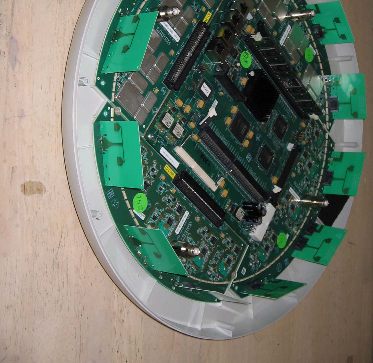
Click to zoom
Application Details
- Equipment Class
- NII - Unlicensed National Information Infrastructure TX
- Date of Grant
- Apr 25, 2005
- Application Purpose
- Original Equipment
- Date of Application
- Apr 25, 2005
- Equipment Note
- XS-3900 Wireless LAN Array
- Frequency Range
- 5260.00000000 - 5320.00000000
- Company
- Cambium Networks
- Country
- United States
Documents & Files
Document Text
Text extracted from the exhibit documents filed with the FCC. Open a document above to read the original.
Users Manual
XS 3900/3700 WirelessWireless WirelessWireless Wireless LAN ArrayLAN Array LAN ArrayLAN Array LAN Array User’s Guide April 12th, 2005 DRAFT RELEASE (C) Copyright © 2005 Xirrus, Inc. 370 North Westlake Blvd, Suite 200 Westlake Village, CA 91362 USA www.xirrus.com All rights reserved. This document may not be reproduced or disclosed in whole or in part by any means without the written consent of Xirrus, Inc. Part Number: 800-0006-001 (Rev. A) Wireless LAN Array XS-3900, XS-3700, XS-3500 Trademarks is a trademark of Xirrus, Inc. All other trademarks and brand names are marks of their respective holders. Notices FCC Notice This device complies with Part 15 of the FCC Rules, with operation subject to the following two conditions: (1) This device may not cause harmful interference, and (2) this device must accept any interference received, including interference that may cause unwanted operation. This equipment has been tested and found to comply with the limits for a Class A digital device, pursuant to Part 15 of the FCC rules. These limits are designed to provide reasonable protection against harmful interference in a residential installation. This equipment generates, uses and can radiate RF energy and, if not installed and used in accordance with the instructions, may cause harmful interference to radio communications. However, there is no guarantee that interference will not occur in a particular installation. If this equipment does cause harmful interference to radio or television reception, which can be determined by turning the equipment off and on, the user is encouraged to try to correct the interference by one or more of the following safety measures: zReorient or relocate the receiving antenna. zIncrease the separation between the equipment and the receiver. zConsult the dealer or an experienced wireless technician for help. Use of a shielded twisted pair (STP) cable must be used for all Ethernet connections in order to comply with EMC requirements. RF Radiation Hazard Warning To ensure compliance with FCC RF exposure requirements, this device must be installed in a location where the antennas of the device will have a minimum distance of at least 25 cm (9.84 inches) from all persons. Using higher gain antennas and types of antennas not certified for use with this product is not allowed. The device shall not be co-located with another transmitter. Non-Modification Statement Unauthorized changes or modifications to the device are not permitted. Use only the supplied internal antenna, or external antennas supplied by the manufacturer. Modifications to the device will void the warranty and may violate FCC regulations. Please go to the Xirrus Web site for a list of all approved antennas. Indoor Use This product has been designed for indoor use. Operation of channels in the 5250MHz to 5350MHz band is permitted indoors only to reduce the potential for harmful interference to co-channel mobile satellite systems. Maximum Antenna Gain Currently, the maximum antenna gain is limited to 6dBi for operation in the 5250MHz to 5350MHz band and 5725MHz to 5825MHz band and must not exceed maximum EIRP limits set by the FCC / Industry Canada. High Power Radars High power radars are allocated as primary users (meaning they have priority) in the 5250MHz to 5350MHz and 5650MHz to 5850MHz bands. These radars could cause interference and/or damage to LELAN devices used in Canada. Industry Canada Notice and Marking This Class A digital apparatus complies with Canadian ICES-003. Cet appareil numérique de la classe A est conforme à la norme NMB-003 du Canada. The term “IC:” before the radio certification number only signifies that Industry Canada technical specifications were met. Safety Warnings Translated safety warnings appear on the following page. ! Safety Warnings Read all user documentation before powering this device. All Xirrus interconnected equipment should be contained indoors. This product is not suitable for outdoor operation. Please verify the integrity of the system ground prior to installing Xirrus equipment. Additionally, verify that the ambient operating temperature does not exceed 50°C. ! Explosive Device Proximity Warning Do not operate the XS-3900 unit near unshielded blasting caps or in an explosive environment unless the device has been modified to be especially qualified for such use. ! Lightning Activity Warning Do not work on the XS-3900 or connect or disconnect cables during periods of lightning activity. ! Circuit Breaker Warning The XS-3900 relies on the building’s installation for over current protection. Ensure that a fuse or circuit breaker no larger than 120 VAC, 15A (U.S.) or 240 VAC, 10A (International) is used on all current- carrying conductors. Translated Safety Warnings Avertissements de Sécurité ! Sécurité Lisez l'ensemble de la documentation utilisateur avant de mettre cet appareil sous tension. Tous les équipements Xirrus interconnectés doivent être installés en intérieur. Ce produit n'est pas conçu pour être utilisé en extérieur. Veuillez vérifier l'intégrité de la terre du système avant d'installer des équipements Xirrus. Vérifiez également que la température de fonctionnement ambiante n'excède pas 50°C. ! Proximité d'appareils explosifs N'utilisez pas l'unité XS-3900 à proximité d'amorces non blindées ou dans un environnement explosif, à moins que l'appareil n'ait été spécifiquement modifié pour un tel usage. ! Foudre N'utilisez pas l'unité XS-3900 et ne branchez pas ou ne débranchez pas de câbles en cas de foudre. ! Disjoncteur L'unité XS-3900 dépend de l'installation du bâtiment pour ce qui est de la protection contre les surintensités. Assurez-vous qu'un fusible ou qu'un disjoncteur de 120 Vca, 15 A (États-Unis) ou de 240 Vca, 10 A (International) maximum est utilisé sur tous les conducteurs de courant. Software License Agreement PLEASE READ THIS SOFTWARE LICENSE AGREEMENT CAREFULLY BEFORE DOWNLOADING OR USING THE SOFTWARE. BY USING ANY LICENSED MATERIALS OR T…
Text truncated - open the document above for the full version.
Cover Letter(s)
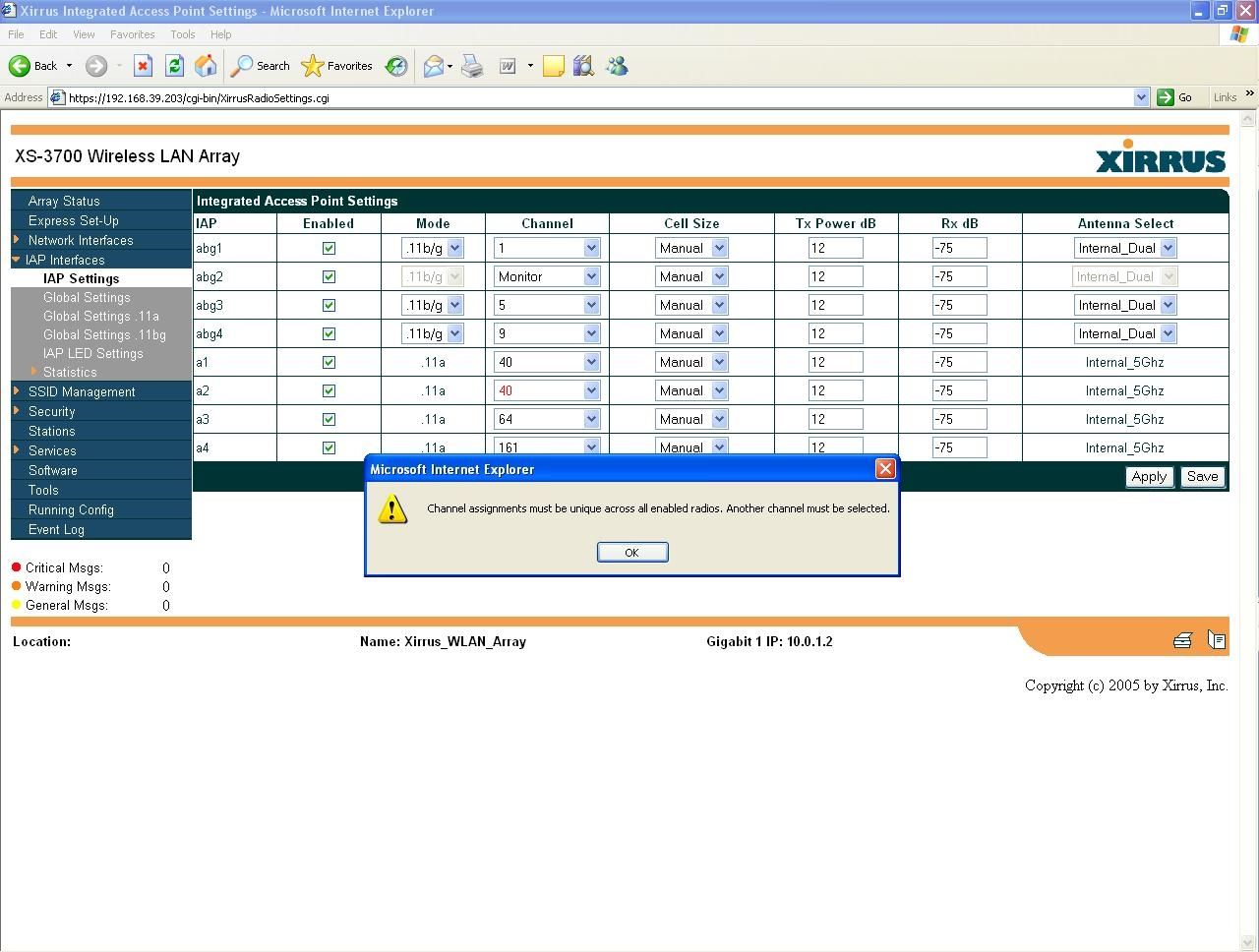
Page 1 of 5 American TCB 4/15/2005 In response to your comments regarding the applications for FCC ID SK6XS390016 please find our responses below: 1) The operational description provided is strictly for the model with 16 transmitters. To clarify this application, is an operational description available for only the model with 8 transmitters to define this application more clearly? One is not available at this time – I have prepared an explanation letter to cover the differences. If more is required please advise. 2) The device appears to be able to have 802.11 b/g capability for 4 transmitters, but it appears to be stated in many locations in the application that only 3 802.11b/g will be used at a time. What limits this to 3? Note that the users manual page 98 suggests that 4 can operate at the same time while Page 6 of the report states Aggregate power is the sum of the output powers from the maximum number of individual transceivers that can operate in the band specified without two trx using overlapping channels. There are only 3 non-overlapping channels available in the band. It would seem if each device is directional in nature that all four could be used and that 3 non-overlapping channels may not be a correct assumption. Additionally, if device are directional, it would seem that it would be possible to transmit the same channel from 2 different radios. Please comment as this may affect assumptions made to sum power (sum across band vs, sum of worse case channels) and MPE calculations. It is possible for all four 802.11abg transceivers to be operational in the 2.4 GHz band simultaneously. The report, aggregated power and form 731 have all been updated. 3) MPE appears to take into consideration 4 802.11 b/g TX’s occurring at the same time, even though other information states only 3 will be used at a time. Please review given 2) above. It is possible for all four 802.11abg transceivers to be operational in the 2.4 GHz band simultaneously. The MPE is correct in this assumption. Page 2 of 5 4) Please clearly define the maximum number of Transmitters that can be used each band given information above in 2) and 3). Note it may be helpful to add a column to the MPE to denote maximum number of channels for each sub band as well to keep understanding of worse case selections to a minimum. (i.e., can all 5 channels be used at the same time in the 5725 – 5850 band?). In addition, could a user not only operate on all 5 channels, but use the same channel more than once in different directions. Additionally, how is this controlled? The GUI interface appears to allow any selection of channels for each radio. It is possible for all four 802.11abg transceivers to be operational in the 2.4GHz band simultaneously. The MPE is correct in this assumption. The MPE calculation has a table on the second page that shows the number of channels available in each band. I have added more comments to try and explain the rationale behind the worst-case mode. To clarify further: 11 channels in the 2412 – 2462 MHz range 4 channels in the 5150 – 5250 MHz band 4 channels in the 5250 – 5350 MHz band 5 channels in the 5725 – 5850 MHz band 5) Page 38 of 113 of the test report, please explain how the power is summed assuming all 5 channels in the band are being used (note 2). For instance, why can’t all 3 directional antennas be for the highest power channel? 3 x 1.675 W + 2 x 0.375 W? Additionally, I can not recreate the maximum summed power listed, even trying to follow the note 2. Also, the power assumes 5 channels, while worse case MPE appears to suggest only 4 can be used (3 directional, 1 additional). Please clarify these inconsistencies. Firstly, Xirrus are removing the high gain external antenna from this application as the use of such a high gain antenna would require them to lock out the use of the external antenna with any of the other 5 GHz bands. The test data, MPE calculations and report have been updated to remove the references to the high gain Maxrad antenna. The test data has been revised to show a corrected aggregated power over all five channels. The aggregated power assumes all five channels at the highest output power (19.7dBm, 0.094W) to give a total of 26.7dBm, or 0.471 Watts. The maximum eirp for each radio is with the internal 6dBi antenna (the external antenna has a high gain of 3dBd, 5.2dBi), which gives a total eirp of 32.7dBm, or 1.875 Watts. Page 3 of 5 6) The interface on page 53 of the users manual suggests that selection of channels may not be mutually exclusive given so many transmitters are enabled on the same channel. If channels are not mutually exclusive, then shouldn’t summing of powers should be based on worse case channel per band multiplied by the maximum number of channels in that band that can be utilized. See additional comments above. The system incorporates lockout of a channel once selected, thereby ensuring a channel can only be selected once. It also locks out the ability the ability to have devices operating on overlapping channels: • the 2400 – 2483.5 MHz band has 11 channels, separated by 5 MHz with a signal bandwidth of between 12 MHz and 17MHz, so there are a maximum of 4 non-overlapping channels in this band – channels 1,4, 7 and 10 or 11). • all other bands have a channel spacing of 20MHz, wider than the 17MHz signal bandwidth. The operational description also references about use of non-overlapping channels. The GUI showing channel lockout has also been uploaded. 7) Is there detailed specifications/information on the two 5 GHz external antennas being approved? The FCC desires this information to be included with the application. The antenna gain information for the 5 GHz antennas was uploaded. It will be revised to remove the high gain antenna. 8) Questions regarding power on page 43 of 113; a) Given information above, what limits the TX to only 4 channels in each band (both 5150- 5250)? See response to (6). b) Why is the power in the second table for aggregati…
Text truncated - open the document above for the full version.
Cover Letter(s)
Page 1 of 3 American TCB 4/13/2005 In response to your comments regarding the applications for FCC ID SK6XS37008 and FCC ID SK6XS390016 please find our responses below: 1) The marketing literature makes mention of "rip and replacement" design functionality and modular nature. I believe in our previous discussions it was decided this would not be possible. Please review, correct, and/or call to discuss if necessary. The advertising literature is indicating that, because Xirrus have separated the radio boards from the processor board future upgrades could be achieved by swapping out the radios to get added/different/upgraded functionality. Xirrus realize that they need to have whatever combination is put together have an FCC approval, and may well pursue a modular approval for subsequent cards. The user’s guide has been updated to remove the appendix “Servicing the WLAN Array”. 2) Careful review of the internal antennas appears to show 2 versions. Please provide photographs of both versions. There is only one version - the antenna in the original picture was modified during testing to evaluate a method of reducing second harmonic signal levels. This was an experiment only and performed on only one antenna. The internal pictures for the 16-port device have been re-taken with the modified card/antenna replaced. Note that all test data supporting this application was taken on unmodified devices. Page 2 of 3 3) Section 15.15(b) prohibits adjustments of any control by the user that will cause operation of a device in violation of the regulations. Accordingly, any proposal to allow the end user to choose extended channels on frequencies outside of an allowable frequency band in the USA is not acceptable. For example, a WLAN device operating according to Section 15.247 on channels 1-11 between 2.4 - 2.483.5 GHz must not have any user controls or software to allow the device to operate on channels 12 and 13 which are outside of the allowed USA band. Please explain how this device is compliant to this requirement for both DTS and UNII bands of operation. The North America SKU for the systems will not permit access to channels outside of the FCC allocations, and will set the maximum output power within each band to the levels stated in the test report. Screen shots of the GUI showing the channels available to be selected have been uploaded as a “user’s manual”. 4) Some of the internal photographs appear to still be for the incorrect model. Please correct. There were not enough of the 2-transceiver cards to fully stuff the device at the time of test. An internal shot showing one of the cards installed into the system, plus 3 4-transceiver cards filling the remaining slots, has been uploaded with comments on the photographs explaining that production systems are configured with either 4 4-port or 4 2-port cards. 5) The advertising literature mentions that the device may have 3 external antennas, however the internal photographs show 4 external antennas. Please explain. Please refer to the external shot that shows access to only 3 of the four external connectors. Providing access to the rf connector on the fourth card would require a major redesign in the enclosure as the area above the connector is occupied by the power supply and associated cabling. Xirrus fully understand that any changes in enclosure design to provide access to the fourth external antenna connector would require a permissive change as the use of higher gain external antennas in the upper 5GHz band would affect MPE calculations. 6) Information in block diagrams and operational description show all radios to be identical. If this is true, please explain why only 4 of the 8 can TX at 2.4 GHz and not all 8 Tx. There are 2 types of radios on each radio board. One radio on each board has an additional PA to allow usage in the 2.4GHz band. The block diagrams have been updated and uploaded. Page 3 of 3 7) Please provide information regarding the gain of the internal antenna for both 2.4 and 5 GHz. Only one value appears to be reported. The internal antennas have 6dBi gain in each band (one has 6dBi gain in the 2.4GHz, the other has 6dBi gain in the 5 GHz band) 8) Are test configuration photographs for radiated emissions with external photographs available. Unfortunately not, the media card for those shots was corrupted (we have since replaced all our digital cameras). For the tests with external antennas the omni antenna were mounted such that the antenna was vertical. For the panel antennas the antennas were mounted so that the panel was facing the measurement antenna. The following documents have been uploaded to the ATCB website to support the responses above for FCC ID: SK6XS390016 (16-port) • xs_userguide_c April 12 05.pdf (User’s guide) • GUI for channel selection.pdf (User’s guide) • Internal Photos (16-Trx) revision 2.pdf • XS3900 Block Diagram rev 2.pdf The following documents have been uploaded to the ATCB website to support the responses above for FCC ID: SK6XS37008 (8-port) • xs_userguide_c April 12 05.pdf (User’s guide) • GUI for channel selection.pdf (User’s guide) • XS3700 Block Diagram revision 2.pdf • Internal Photos - revision 2.pdf Regards, Mark Briggs Principal Engineer
ID Label/Location Info
Wireless LAN Array 7.4352" 6.4776" .1980" R0.0720" 3.4781" 0.2205" R0.2395" 6.4535" R6.9368" R0.025" 2.6973" 4.15" 370 North Westlake Blvd., Suite 200 Westlake Village, CA 91362 USA Product Label, XS3900-16 836-0003-001 1/13/05 B REV Scale: 1:1 DWG. NO. Name: Drawn: Karine Hovsepian Ian Laity Checked: Material: Lexan Graphic Film 8B35(Matte) Date: Title: 6.4776 0.355" DIELINE DOES NOT PRINT TEXT IS BLACK CMYK Match Pantone 543 CMYK Match Pantone 116 C=0 M=2 Y=5 K=9 NOTE TO VENDOR CALLOUT DOES NOT PRINT This device complies with Part 15 of the FCC Rules. Operation is subject to the following two conditions: (1) This device may not cause harmful interference, and (2) this device must accept any interference received, including interference that may cause undesired operation. This Class A digital apparatus complies with Canadian ICES-003 Cet appareil numérique de la classe X est conforme à la norme NMB-003 du Canada IC: 5428A-XS390016 FCC ID: SK6XS390016 Westlake Village, California 91362 INTERPRET GEOMETRIC DRAWING IS THE SOLE PROPERTY OF TWO PLACE DECIMAL D C B A B C D 123 45 6 7 8 8 76 5 4 3 2 1 E F REV SCALE: XIRRUS. ANY REPRODUCTION IN PART .015 E F 180-0001-001 185-0001-001 C2 370 North Westlake Blvd. Suite 200 A C I. LAITY C. LEONARD PROPRIETARY AND CONFIDENTIAL 2/4/2005 DWG. NO. PART NO. TOLERANCING PER ASME Y14.5M UNLESS OTHERWISE SPECIFIED: 1:3 THREE PLACE DECIMAL OR AS A WHOLE WITHOUT THE WRITTEN TLA,XS3900-16,LABELED 11/2/2004 SIZE TITLE: DO NOT SCALE DRAWING THE INFORMATION CONTAINED IN THIS PERMISSION OF XIRRUS IS PROHIBITED. .005 MATERIAL FINISH DRAWN CHECKED ENG APPR. MFG APPR. Q.A. COMMENTS: DATE NAME DIMENSIONS ARE IN INCHES TOLERANCES: FRACTIONAL 1/4 ANGULAR: MACH 1/4 BEND 1/4 SHEET 1 OF 1 4 SCALE 2 : 1 TYP, 4 PLACES, RADIALLY DETAIL D 4 3 2 3 4 5 ALIGN TAB ON EMBLEM WITH SLOT IN EMBLEM RECESS. CENTER EMBLEM WITHIN CIRCULAR EMBLEM RECESS. PRODUCT LABEL AND ALIGNMENT LABELS MUST BE INSTALLED PRIOR TO INSTALLING BRACKET ONTO UNIT. CENTER ALIGNMENT INDICATOR LABEL BETWEEN TWO VERTICAL RIBS ON BRACKET, DO NOT OVERLAP TOP OR BOTTOM EDGE OF BRACKET. BRACKET REMOVAL LABEL ARROW MUST BE ALIGNED WITH RIB AS SHOWN. DO NOT OVERLAP TOP OR BOTTOM EDGE OF BRACKET. ALIGN BRACKET AS SHOWN AND TWIST CLOCKWISE TO LOCK IN PLACE. 1 1 EMBLEM, 1.5, XS3900 830-0006-001 ITEM NO. PART NO. DESCRIPTION QTY 6 830-0002-001 BRACKET, MOUNTING 1 1. SPLIT BALLOONS CONTAIN ITEM NUMBER IN THE TOP PORTION AND QUANTITY IN THE BOTTOM PORTION. NOTES: LABEL PRODUCT, XS3900-16 1 5 170-0001-001 TLA, XS3900-16, UNLABELED 1 4 830-0014-001 XS3900,LABEL, ALIGNMENT INDICATOR 4 3 830-0013-001 XS3900,LABEL, BRACKET REMOVAL 1 2 220-0001-001 C. LEONARD REVISIONS ZONEREV.DESCRIPTIONDATEBYAPPROVED AINITIAL RELEASE11/2/2004 C. LEONARD I. LAITY B CHANGED SHAPE OF PRODUCT LABEL TO RECTANGLE 12/21/2004 C. LEONARDI. LAITY C REPLACED PRODUCT LABEL 830-0003-001 WITH 830-0002-001 1/27/2005 C. LEONARDI. LAITY C1 TITLE WAS "TLA, MCAP16, LABELED" 1/28/2005 C. LEONARDI. LAITY C2 ADDED 2 LABELS; ALIGNMNET, AND BRACKET REMOVAL 2/3/2005I. LAITY 2 3 1 6 1 1 1 2 3 5 1 5 3 4
RF Exposure Info
MPE Calculations The device is not a portable device (i.e. intended to be worn on the body or be hand- held), so it is classified as being either a mobile device or a fixed mounted device. The user’s manual specifies a minimum separation distance of at least 20cm, consistent with this classification. FCC part 1.1310, Table 1 limits the power density for uncontrolled exposure. The power density, P d (mW/cm 2 ) calculated from the maximum EIRP, P t (mW) and the distance, d (m), between the transmitting antenna and the closest person, can be calculated using: P d = P t /(4 πd 2 ) Frequency MPE Limit (mW/cm 2 ) Eirp (mW) 1 Pd at 20cm (mW/cm 2 ) Distance where Pd = limit (cm) 2400 to 5850 MHz 1.00 3672.8 2 0.7 17.1 • 1 Equivalent isotropic output power is the total eirp summed across all active transmitters. There are 16 transmitters available, 4 that can use the 2.4 GHz band and all 16 are capable of operating in the 5GHz bands. The worst case eirp in the table above is for the worst case configuration, based on the channels used being those with the highest output power. Refer to the table on the following page for the total eirp calculations. • 2 This calculation assumes that all transceivers are connected to antennas with gains of 6dBi (highest gain antenna available in any band). As shown in the calculations above, the power density 17.1 cm from the device is below the maximum permitted level for uncontrolled exposure. The instructions in the user’s manual require a separation distance of at least 25cm. Calculation Tables For Determining Total EIRP Across All 16 Transmitters The calculations for maximum eirp do not take into account the fact that: • All transmitters do not tran smit with a 100% duty cycle • The majority of antennas used (at least 12 of the 16) are directional antennas with lit tle overlap in the main beams from each antenna The calculations are, therefore, a conservative es timate for the rf hazard presented by the device. Output Power EIRP Total EIRP Band Mode Peak Average Antenna gain (Max) dBm W Channels Available Channels Used W dBm 2400 - 2483.5 OFDM 21.3 16.7 6.0 22.7 0.186 2401 - 2483.5 CCK 18.0 16.7 6.0 22.7 0.186 11 4 0.745 28.72 5150 - 5250 OFDM 11.0 6.0 17.0 0.050 4 3 0.149 21.73 5250 - 5350 OFDM 17.6 6.0 23.6 0.231 4 4 0.923 29.65 5725 - 5850 OFDM 19.7 - 6.0 25.7 0.372 5 5 1.858 32.69 Totals: 16 3.674 35.65 The system incorporates a lock-out mechan ism to prevent a channel being used more than once, therefore the maximum number of transmitters in each band is limited to the lower of number of channels available or number of transceivers capable of operatin g in the band. 4 transceivers can operate in the 240 0-2483.5 MHz band. All 16 transceivers can operate in the 5150 - 5250MHz, 5250-5350MHz and 5725-5850MHz bands. Operation in any ba nd does not allow any two radios to use the same channel or to use overlapping channels (the only band with overlapping channels is the 2.4GHz band which has a 5 MHz channel spacing and a 6dB signal bandwidth of between 12 MHz (for 802.11b) and 17 MHz (802.11g). Maximum eirp is calculated using the highest average power for each channel (where give n), otherwise it uses the highest peak p ower. As there are 16 transceivers available, th e transceivers are assigned to the availabl e channels in order of decreasing power as follows: • The 5725-5850 MHz band has the highest eirp, and 5 channels available so the first five transceivers are allocated to that band ; • The band with the next highest eirp per ch annel is the 5250-5350 MHz band, with four channels, so the next four transceivers are placed in that band (total of nine transceivers used so far); • There are only four radios capable of operating in the 2400 – 2483.5 MHz band, which has the third highest eirp, so all four of the remaining seven transceivers are allocated to that band; • The remaining three radios are allocated to the last remaining band, the 5150 - 5250 MHz band.
Test Report
File: R58645 Page 1 of 24 2016-01 Electromagnetic Emissions Test Report and Application for Grant of Equipment Authorization pursuant to FCC Part 15, Subpart C (15.247) DTS Specifications FCC Part 15 Subpart E (UNII Devices) and Industry Canada RSS 210 Issue 5 (LELAN Devices) on the Xirrus, Inc. Model: XS-3900 (XS-3900-16 and XS-3700-8) FCC ID: SK6XS390016 and SK6XS37008 UPN: 5428A-XS390016 and 5428A-XS37008 GRANTEE: Xirrus, Inc. 370 North Westlake Blvd., Suite 200 Westlake Village, CA 91362 TEST SITE: Elliott Laboratories, Inc. 684 W. Maude Avenue Sunnyvale, CA 94086 REPORT DATE: March 29, 2005 FINAL TEST DATE: January 24, January 27, January 28, January 29, February 1, March 28, 2005 AUTHORIZED SIGNATORY: ______________________________ Mark Briggs Vice President of Engineering Elliott Laboratories, Inc. is accredited by the A2LA, certificate number 2016-01, to perform the test(s) listed in this report. This report shall not be reproduced, except in its entirety, without the written approval of Elliott Laboratories, Inc. Elliott Laboratories, Inc. -- EMC Department Test Report Report Date: February 7, 2005 File: R58645 Page 2 of 24 pages DECLARATIONS OF COMPLIANCE Equipment Name and Model: XS-3900 Manufacturer: Xirrus, Inc. 370 North Westlake Blvd., Suite 200 Westlake Village, CA 91362 Tested to applicable standards: RSS-210, Issue 5, November 2001 (Low Power License-Exempt Radiocommunication Devices) FCC Part 15.247 (DTS) FCC Part 15 Subpart E (UNII Devices) Measurement Facility Description Filed With Department of Industry: Departmental Acknowledgement Number: IC2845 SV1 Departmental Acknowledgement Number: IC2845 SV3 I declare that the testing was performed or supervised by me; that the test measurements were made in accordance with the above mentioned departmental standards (through the use of ANSI C63.4 as detailed in section 5.3 of RSS-210, Issue 5); and that the equipment performed in accordance with the data submitted in this report. Signature ______________________________ Name Mark Briggs Title Vice President of Engineering Company Elliott Laboratories Inc. Address 684 W. Maude Ave Sunnyvale, CA 94086 USA Date: February 7, 2005 Maintenance of compliance with the above standards is the responsibility of the manufacturer. Any modification of the product which may result in increased emissions should be checked to ensure compliance has been maintained (i.e., printed circuit board layout changes, different line filter, different power supply, harnessing or I/O cable changes, etc.). Elliott Laboratories, Inc. -- EMC Department Test Report Report Date: February 7, 2005 File: R58645 Page 3 of 24 pages TABLE OF CONTENTS COVER PAGE.............................................................................................................................................................1 DECLARATIONS OF COMPLIANCE ................................................................................................................... 2 TABLE OF CONTENTS ........................................................................................................................................... 3 SCOPE......................................................................................................................................................................... 5 OBJECTIVE ............................................................................................................................................................... 5 SUMMARY OF RESULTS ....................................................................................................................................... 6 FCC PART 15.247, RSS 210 Ò 2400 Ò 2483.5 MHZ................................................................................................ 6 FCC PART 15.247, RSS 210 Ò 5725 - 5850 MHZ.................................................................................................... 7 FCC PART 15E, RSS 210 Ò 5150 - 5350 MHZ........................................................................................................ 8 FCC PART 15.109 (RECEIVER), FCC PART 15.207/15.107, RSS 210 (RECEIVER AND AC CONDUCTED EMISSIONS)............................................................................................................................................................. 9 EQUIPMENT UNDER TEST (EUT) DETAILS.................................................................................................... 10 GENERAL............................................................................................................................................................. 10 ANTENNA ............................................................................................................................................................ 11 ENCLOSURE........................................................................................................................................................ 11 MODIFICATIONS................................................................................................................................................ 11 SUPPORT EQUIPMENT...................................................................................................................................... 12 EUT INTERFACE PORTS.................................................................................................................................... 12 EUT OPERATION DURING TESTING .............................................................................................................. 13 TEST SITE.......................................................................................................................…
Text truncated - open the document above for the full version.
Contact Information
Applicant
Steven M Payne(Principal Staff Engineer - RF)
Technical Contact
Elliott Laboratories Inc.Mark Briggs
[email protected]408-245-7800
684 West Maude Ave. · Sunnyvale, California · United States
Non-Technical Contact
Elliott Laboratories Inc.David Guidotti
[email protected]408-245-7800
Test Firm
Elliott Laboratories Inc.David Bare
Technical Specifications
| # | Rule Parts | Frequency Range | Power Output |
|---|---|---|---|
| 2 | 15E | 5.26 GHz - 5.32 GHz | 58.00 mW |
Other Applications from Cambium Networks

SK6-XH2120
Sep 23, 2015Hardened Wireless Access Point
Equipment Class
DTS - Digital Transmission System
SK6-X2120
Sep 08, 2015Wireless Access Point
Equipment Class
DTS - Digital Transmission System
SK6-XDR130
Jun 02, 2015Wireless Access Point Radio module
Equipment Class
NII - Unlicensed National Information Infrastructure TX
SK6-XR320
Nov 24, 2014Wireless Access Point
Equipment Class
NII - Unlicensed National Information Infrastructure TX
SK6-XI-AC867
Jun 08, 2014Wireless Access Point
Equipment Class
NII - Unlicensed National Information Infrastructure TX