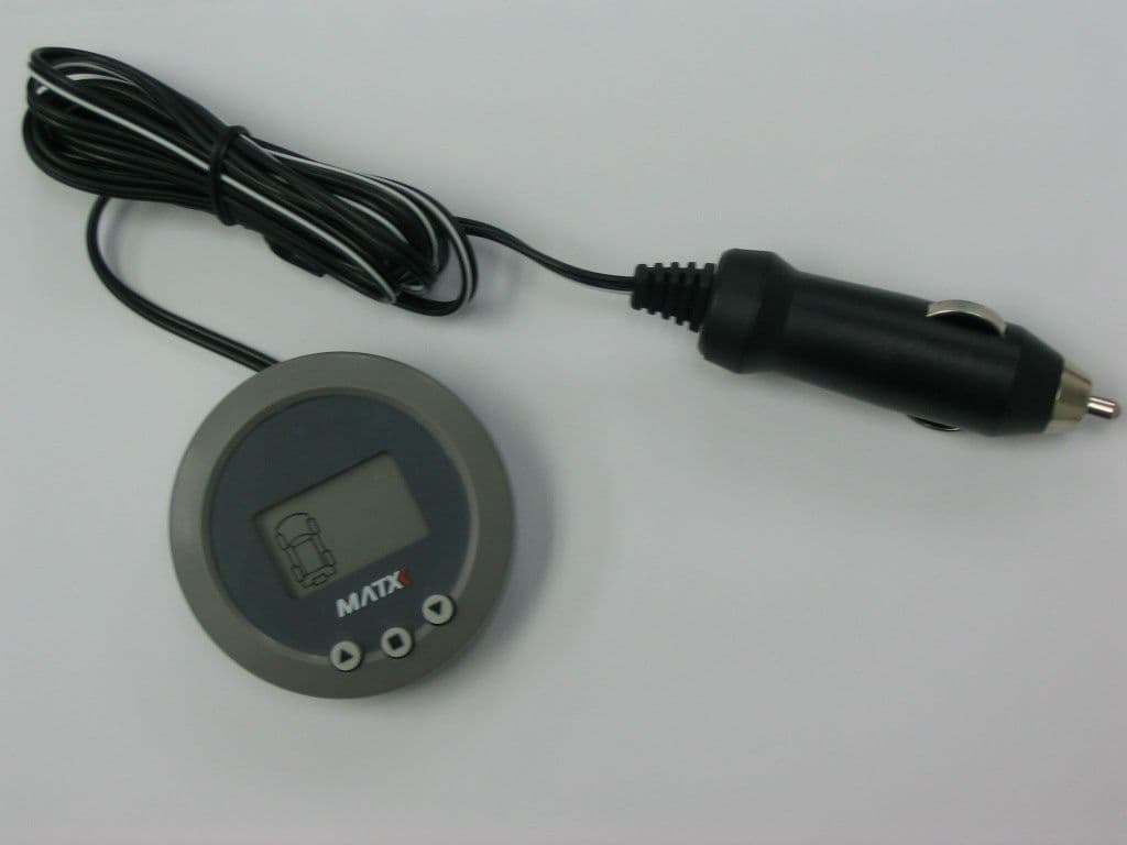
SMYMATX800Tire Pressure Monitoring System
TS Matrix Auto Sdn.Bhd.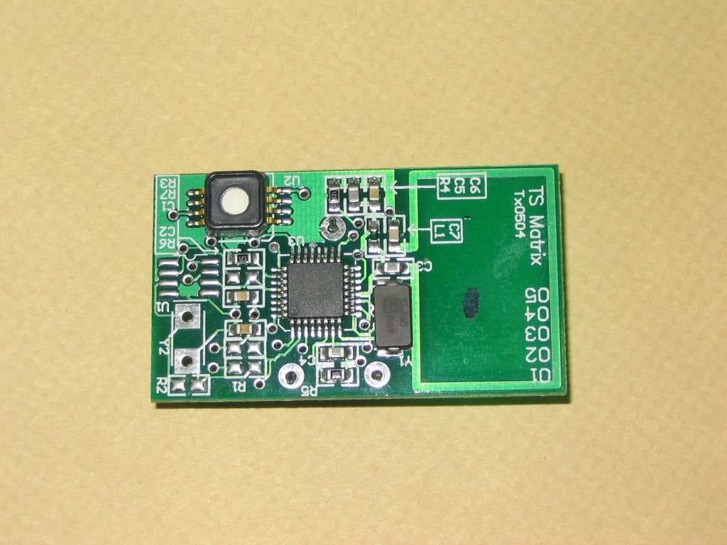
Click to zoom
Application Details
- Equipment Class
- DXX - Part 15 Low Power Communication Device Transmitter
- Date of Grant
- Dec 08, 2004
- Application Purpose
- Original Equipment
- Date of Application
- Oct 21, 2004
- Equipment Note
- Tire Pressure Monitoring System
- Frequency Range
- 433.92000000 - 433.92000000
- Company
- TS Matrix Auto Sdn.Bhd.
- Country
- Malaysia
Documents & Files
Document Text
Text extracted from the exhibit documents filed with the FCC. Open a document above to read the original.
Users Manual
TABLE OF CONTENT Notices 1. Objectives 2. Descriptions 3. Normal Operations Automatic and Manual Scroll Pressure or Temperature Display Power saver Mode 4. Alerts 5. Others Switching off Display Module Low Battery Warning Changing Tire Position Tire Replacement Wheel Rim Replacement Sensor Module Replacement 6. Installation Install Sensor Modules Configure Display Module Install Display Module De-installation of Tire 7. Programming 8. Troubleshooting 9. Technical Specifications Record of Sensor Module Position ii 01 02 - 03 04 05 06 - 07 08 - 13 14 - 19 20 - 21 22 i Back Cover NOTICES System Usage MATX TIRE MONITORis a safety device that issues audio and visual alerts to users upon predefined tire conditions. It is the user's responsibility to react promptly and appropriately to alerts, and to rectify the conditions as soon as possible. MATX TIRE MONITORis suitable for use in passenger cars and light trucks with not more than 5 radial (tubeless) tires. For vehicles with more tires, useMATX TIRE MONITORfor trucks and buses. This system will not function in bias tires. System Installation Use ofMATX TIRE MONITORrequires that it has been properly installed and programmed by qualified personnel according toMATX TIRE MONITOR'Sdocumentation. This includes the Owner's Manual, any supplementary instructions included with the product, and any installation guide issued to dealers or installers. Reacting to Alerts When an alert is shown, reduce vehicle speed to an appropriate safe level and proceed to a safe stopping location where tires can be inspected. Low pressure alerts indicate tire inflation is needed at the soonest opportunity. Rapid deflation alert is normally triggered by a puncture and therefore, the wheel needs to be replaced before continuing the journey. High pressure alert implies that tire needs to be deflated and re-inflated to the optimum pressure. High temperature alert may be caused by severe under inflation, hard sustained braking, vehicle overload and sustained high speeds, and need to be rectified accordingly. Use of Chemicals Temporary resealing or re-inflation products that require addition of sealant or propellant chemicals inside any tire may adversely affect the operation of the sensor module. Power Consumption If a display module is connected in such a way that it is always on (e.g. via cigarette lighter power socket that is always 'live' or hardwiring before the ignition switch), it is advisable to switch it off before extended period of parking (more than three days), in order to avoid battery draining. DISCLAIMER A properly installed, programmed and functioning MATX TIRE MONITORis capable of alerting the user on pre- determined low and high tire inflation pressure, and high tire internal temperature conditions. It is the user's responsibility to react promptly and appropriately to alerts, and to rectify the conditions as soon as possible. TS Matrix Auto Sdn. Bhd., and its holding companies are not responsible for any loss of life, physical and psychological injuries, as well as property damages due to improper installation or inappropriate use of MATX TIRE MONITOR , or failure to response promptly to alerts issued byMATX TIRE MONITOR. ii 01 1. OBJECTIVES MATX TIRE MONITORcontinuously measures inflation pressure and internal temperature of individual tires. It displays the measurement data and issues audio and visual alerts during any of the following conditions: Pressure of any tire is lower than an user-determined level Pressure of any tire is lower than the recommended safety level Pressure of any tire is higher than the recommended safety level Internal temperature of any tire is higher than the recommended safety level Pressure of any tire is decreasing rapidly (e.g. when tire is punctured) Upon detection of any alert, users are advised to slow down immediately and gently bring the vehicle to a stop at a safe location to inspect the tires. It is the users' responsibility to react promptly and to rectify the situation as soon as possible. 02 AMATX TIRE MONITORconsists of 2 principal parts - sensor modules and display module. A sensor module is to be mounted on each wheel rim using metal strap provided. Each sensor module measures temperature and pressure inside the tire, processes measurement data, and wirelessly transmits signals to the display module. Sensor modules are powered by built-in battery with minimum life of 5 years or 100,000 km (60,000 miles). Optional sensor modules can be purchased separately to monitor spare tire or to replace existing parts. Each sensor module is uniquely coded. A display module is to be installed inside the vehicle cabin using sticky tape provided. It receives wireless signals from dedicated sensor modules, display the information and show audio and visual alerts at user-determined and pre-programmed levels. Display module can be plugged into the vehicle's cigarette lighter power outlet or hardwired into vehicle's main power circuitry. 2. DESCRIPTIONS Complete System 1. Sensor Modules 2. Display Module 3. Metal Strap 4. Fastener 5. Valve Cap 6. Owner's Manual 7. Warranty Card 1. Unique Identity Code 2. Loops for Metal Straps Sensor Module 03 2. DESCRIPTIONS 1. 'Up' button 2. 'Mode' button 3. 'Down' button 4. Screen 5. Antenna 6. Holder 7. Sticky tape 8. Power cord 9. Power plug Display Module Screen Display 1. Programming Mode 2. Low battery alert 3. Pressure data indicator 4. Low pressure alert 5. Temperature data indicator 6. Pressure or temperature reading 7. Temperature units 8. Pressure units 9. Automatic scroll 04 3. NORMAL OPERATIONS Automatic and Manual Scroll During normal operations, a display module shows pressure or temperature data for one tire at a time. The display will automatically scroll on to show the reading of the next tire after 3 seconds. The user may press 'Up' or 'Down' button to manually select any tire for data display. Pressure or Temperature Display To toggle between pressure and temperature display,…
Text truncated - open the document above for the full version.
Block Diagram
Matx TPMS System Diagram Transmitter Module ANTENNA 3V LithiumBatteryMCU +RF Module Pressure & Temperature Sensor Receiver Module ANTENNA RF Receiver IC LCD MCU KEYPAD To Car 12V Power Supply 433.92MHz
ID Label/Location Info
A subsidiary of TS Matrix Bhd.A member of Tuan Sing Group PART DRAWING/SPECIFICATION ID Label Location of Label Remarks: Label and Location Drawn: KV Date: 22 OCT 04Part No.: S800-LABEL
Operational Description
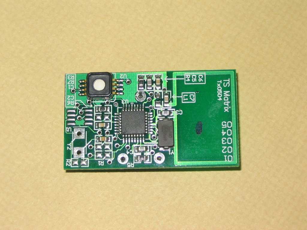
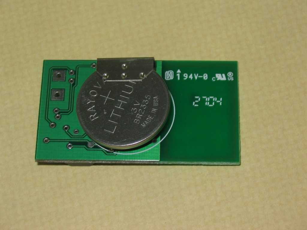
Matx Operation Description Operations Matx tire monitor consists of two principal parts – sensor modules and display module. Sensor module is mounted on each rim using metal strap. Each sensor module measures temperature and pressure inside the tire, processes measurement data and wirelessly transmits signals to the display module. Sensor module is operated by lithium 3V battery. Display module inside the vehicle cabin receives wireless signals from sensors modules, display the information and show audio and visual alerts at user determined and pre-programmed level. The display module is supplied by vehicle power supply. Sensor module The sensor module consists of a RF+MCU IC, pressure sensor and very few external components for operation. The transmitter uses a 13.56MHz crystal as a reference oscillator for its phase lock loop (PLL). Antenna was printed on the PCB. No tuning is required for the unit. Display Module In the display module, a RF IC receives wireless signal is connected to a MCU. The MCU will processed the received signal and display in the LCD panel. Communication The system is operating at 433.92MHz +/- 75kHz. The sensor transmits signal to display unit utilizing frequency shift keying (FSK) at 9600 bps. It is only a one way communication system. FSK is defined as a signal whose frequency shifts between two values to represent a digital high and low signal. In this system a digital high is a lower frequency and a digital low is a higher frequency. In other words, if the carrier frequency is 433.92 MHz and the total frequency deviation is defined as ±fdev, then a digital high is at 433.92 MHz – 75kHz and a digital low is at 433.92 MHz + 75 kHz. Diagram of the Carrier Wave with FSK and Manchester Encoding The data format of the transmitted signal PreambleDevice IDPressureTemperatureChecksumStop Bits 16 bits32 bits8 bits8 bits8 bits2bits
Schematics
1 2 3 4 5 6 ABCD 6 5 4 3 2 1 DCBA Title Number Revision Size B Date: 19-Oct-2004 Sheet of File: C:\TPMS\PCB Drawing\MyDesign.ddb Drawn By: VDD 24 VCC 14 PTA3 31 PTA6 28 PTA5 29 BAND 17 PTA2 32 PTA4 30 GNDRF 13 REXT 9 CFSK 10 VCC 11 RFOUT 12 ENABLE 15 MODE 16 PTB3 20 OSC1 21 OSC2 22 VSS 23 DATACLK 19 DATA 18 IRQ1 25 RST 26 PTA7 27 PTA1 1 PTB1 4 PTA0 2 XTAL0 8 XTAL1 7 GND 6 PTB2 5 PTB0 3 U3 68HC908RF2 SO 8 RSTB 5 DATA 6 CLK 7 S1/VPP 1 OUTB 4 VDD 2 VSS 3 U2 DAYTONA + 1 - 2 BT1BATTERY C2 0.1uF GND R312K Y1 13.56MHz C4 6.8pF R5 100K GND GND R4 12K C5100pFC610nF C70.47pF ANT C110nF GND TCat Transmitter R210M VCC VCC R610K VCC 2 Mar 04 L112nH VCC C347pF R110K NetLabel25 23 6 74 8 SHDN U1 TLV2770 GNDVCC Y2PIEZO GND GND VCC R710M
Test Report
Justification for compliance with 15.231 a) 1, 2 and 3 (1) A manually operated transmitter shall employ a switch that will automatically deactivate the transmitter within not more than 5 seconds of being released. (2) A transmitter activated automatically shall cease transmission within 5 seconds after activation. (3) Periodic transmissions at regular predetermined intervals are not permitted. However, polling or supervision transmissions, including data, to determine system integrity of transmitters used in security or safety applications are allowed if the total duration of transmissions does not exceed more than two seconds per hour for each transmitter. There is no limit on the number of individual transmissions, provided the total transmission time does not exceed two seconds per hour. Justification (1) The transmitter is not manually operated. Therefore, this clause is not applicable. (2) The transmitter samples the tire pressure and temperature every 70 seconds. If a change in pressure or temperature is detected, 10 12.5ms signal in series will be transmitted. It will enter into sleep mode upon completion of the transmission, which is less than 5 second. (3) If there is no transmission for the last 210 seconds, the transmitter will transmits 5 12.5ms signal to ensure integrity of data in the receiver. It will enter into sleep mode upon completion of the transmission, which is less than 5 second. The total transmission time in one hour is 3600 seconds / 210 seconds X 12.5 ms X 5 = 1071 ms This is less than 2 seconds per hour as required in clause 3.
Contact Information
Applicant
Lee Teik Chong(Director Of Engineering Design)
Non-Technical Contact
TS Matrix Auto Sdn.Bhd.Jane Koh
[email protected]603-78769433
Test Firm
SIRIM QAS Sdn. BhdShiak Jamaldin
Technical Specifications
| # | Rule Parts | Frequency Range | Power Output |
|---|---|---|---|
| 1 | 15C | 433.92 MHz - 433.92 MHz | - |
Other Applications from TS Matrix Auto Sdn.Bhd.
SMYMATXD800
Jan 05, 2005Tire Pressure Monitoring Syste,
Equipment Class
CYY - Communications Receiver used w/Pt 15 Transmitter