SOFSKYTRACKERUser RF Link
Applied Digital, Inc.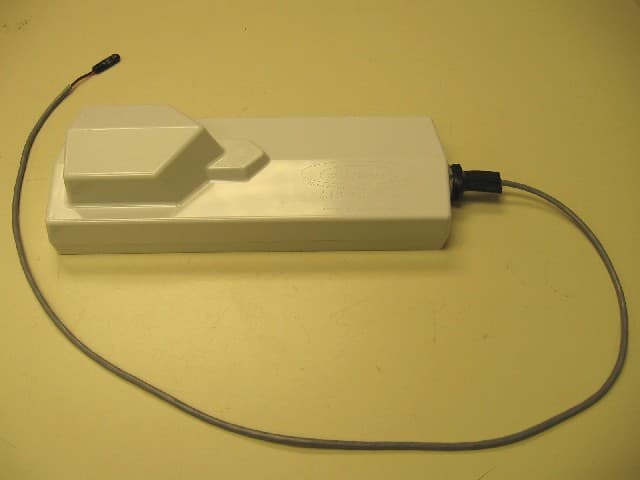
Click to zoom
Application Details
- Equipment Class
- DXX - Part 15 Low Power Communication Device Transmitter
- Date of Grant
- Feb 15, 2006
- Application Purpose
- Original Equipment
- Date of Application
- Feb 15, 2006
- Equipment Note
- User RF Link
- Frequency Range
- 902.00000000 - 928.00000000
- Company
- Applied Digital, Inc.
- Country
- United States
Documents & Files
Document Text
Text extracted from the exhibit documents filed with the FCC. Open a document above to read the original.
Users Manual
SkyTracker FCC Class B Notice FCC ID: SOW SKYTRACKER Note: This equipment has been tested and found to comply with the limits for a Class B digital device, pursuant to part 15 of the FCC Rules. These limits are designed to provide reasonable protection against harmful interference in a residential installation. This equipment generates, uses, and can radiate radio frequency energy and, if not installed and used in accordance with the instructions may cause harmful interference to radio communications. However, there is no guarantee that interference will not occur in a particular installation. If this equipment does cause harmful interference to radio or television reception, which can be determined by turning the equipment off and on, the user is encouraged to try to correct the interference by one or more of the following measures: • Reorient or relocate the receiving antenna. • Increase the separation between the equipment and receiver. • Connect the equipment into an outlet on a circuit different from that to which the receiver is connected. • Consult the dealer or an experienced radio/TV technician for help.
Cover Letter(s)
Applied Digital, Inc.Applied Digital, Inc. Computerized Automation and Controls Attention: Reviewing Engineer Federal Communications Commission 1/12/2006 RE: Confidentiality Request for FCC ID: SOF SKYTRACKER To Whom It May Concern: This letter serves as an official request for confidentiality under FCC Rule Section 0.459. We request that block diagrams, operational descriptions, documents marked as confidential, and schematics required for submission with this application be withdrawn from public review. The reason for this request is that the documents are company proprietary information that we do not wish to make available to our competitors. Sincerely, William J. Stone Applied Digital Inc.
External Photos
External Photos
ID Label/Location Info
FCC Label Location
Internal Photos
Internal Photos
Test Report
TEST REPORT Report Number: 3088423MIN-009 Project Number: 3088423 January 12, 2006 Evaluation of the Sky Tracker Propane Monitor System RF Link FCC ID: SOFSKYTRACKER to FCC Part 2 FCC Part 15, Subpart C, Section 15.249 For Applied Digital Inc. Test Performed by: Test Authorized by: Intertek 7250 Hudson Blvd. Suite 100 Oakdale, MN 55128 Applied Digital Inc. 19315 North Highway 413 Branson West, MO 65737 Prepared by: Date: January 12, 2006 Norman Shpilsher Reviewed by: Date: January 12, 2006 Uri Spector FCC ID: SOFSKYTRACKER January 2006 Page 2 of 31 CONTENTS 1.0 GENERAL DESCRIPTION ........................................................................................................... 3 1.1 Related Submittals Grants................................................................................................................ 3 1.2 Product Description ......................................................................................................................... 3 1.3 Test Methodology ............................................................................................................................ 3 1.4 Test Facility ..................................................................................................................................... 3 2.0 SYSTEM TEST CONFIGURATION............................................................................................. 4 2.1 Justification ...................................................................................................................................... 4 2.2 EUT Setup........................................................................................................................................ 4 2.3 EUT Exercising Software ................................................................................................................ 4 2.4 Special Accessories.......................................................................................................................... 4 2.5 Equipment Modification .................................................................................................................. 4 2.6 Support Equipment List and Description.........................................................................................4 2.7 Test Configuration Block Diagrams ................................................................................................ 5 3.0 TEST RESULTS ............................................................................................................................. 6 3.1 Field Strength of Fundamental, FCC 15.249(a)............................................................................... 7 3.3 Out of Band Emissions, FCC 15.249(d), 15.209 ........................................................................... 21 3.4 Bandwidth of Emissions, FCC 15.215........................................................................................... 24 3.5 Radiated Emissions, FCC 15.109 ..................................................................................................27 3.6 Test Procedure ............................................................................................................................... 29 3.7 Field Strength Calculation ............................................................................................................. 30 4.0 TEST EQUIPMENT..................................................................................................................... 31 FCC ID: SOFSKYTRACKER January 2006 Page 3 of 31 1.0 GENERAL DESCRIPTION 1.1 Related Submittals Grants This is single application of the Applied Digital Inc. Propane Monitor System (trademark Sky Tracker) RF Link for Certification under FCC Part 15, Subpart C. There are no other simultaneous applications. The Receiver portion will be verified under Declaration of Conformity. 1.2 Product Description The Propane Monitor System is a system to monitor propane tank levels providing the RF Link to other monitoring devices and also transmitting data via the satellite link. The satellite link is previously certified by FCC (FCC ID: L2V2100-0149). The RF Link transmitter operates at single channel in frequency range 902 to 928MHz with lowest frequency channel of 903MHz and highest frequency channel of 927MHz. The intended use of the RF Link transmitter is to generate and transmit a RF signal with propane tank status data to other monitoring device receiver. The Propane Monitor System is powered at 3VDC from internal batteries. Antenna Description: The antenna is a non-detachable (soldered to the PCB) 75mm wire as a monopole antenna. The antenna is located under the device cover. Sample Submitted: November 11, 2005 Test Work Started: December 9, 2005 Test Work Completed: January 11, 2006 1.3 Test Methodology Emission measurements were performed according to the procedures in ANSI C63.4-2003. All field strength radiated emissions measurements were performed in the semi-anechoic chamber, and for each scan, the procedure for maximizing emissions in were followed. All field strength radiated tests were performed at an antenna to EUT distance of 3 meters, unless stated otherwise in the "Justification Section" of this Application. 1.4 Test Facility The test site facility used to collect the radiated and conducted measurement data is located at 7250 Hudson Blvd., Suite 100, Oakdale, Minnesota. This test facility has been fully described in a report dated on March 2003 submitted to FCC. Please reference the site registration number: 90706, dated December 6, 2005. FCC ID: SOFSKYTRACKER January 2006 Page 4 of 31 2.0 SYSTEM TEST CONFIGURATION 2.1 Justification N/A 2.2 EUT Setup For simplicity of testing, the transmitter was wired (using pre-programmed set of chip U3) to transmit continuously at single frequency of 903, 915, and 927MHz. 2.3 EUT Exercising Software N/A 2.4 Special Accessories There are no special accessories necessary for complia…
Text truncated - open the document above for the full version.
Test Setup Photos
Setup Photos
Contact Information
Applicant
Daniel E Smith(CEO)
Technical Contact
Applied DigitalWilliam J Stone
[email protected]417-272-0761
19315 HWY 413 · West Branson, Missouri · United States
Non-Technical Contact
Applied DigitalWilliam A Hagler
[email protected]417-272-0761
Test Firm
Intertek Testing ServicesUri Spector
Technical Specifications
| # | Rule Parts | Frequency Range | Power Output |
|---|---|---|---|
| 1 | 15C | 902 MHz - 928 MHz | - |
Other Applications from Applied Digital, Inc.

SOFAP-900
Nov 18, 2004Low Power Transceiver
Equipment Class
DXT - Part 15 Low Power Transceiver, Rx Verified