SONSP640GSM1900 & BT Service Point
WideRay Corp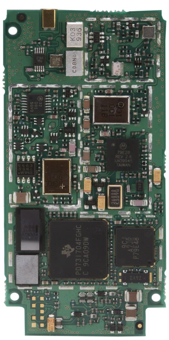
Click to zoom
Application Details
- Equipment Class
- PCB - PCS Licensed Transmitter
- Date of Grant
- Dec 20, 2004
- Application Purpose
- Original Equipment
- Date of Application
- Dec 20, 2004
- Equipment Note
- GSM1900 & BT Service Point
- Frequency Range
- 1850.20000000 - 1909.80000000
- Company
- WideRay Corp
- Country
- United States
Documents & Files
Document Text
Text extracted from the exhibit documents filed with the FCC. Open a document above to read the original.
Users Manual
Frequently Asked Questions 6 Installing the Jack 2 Features of the Jack 1 Jack SP640 User Guide 5 Using the Jack Downloading from the Jack 4 3 Specifications, Supported Devices Features of the Jack ......................................... 2 Front View.................................................................. 2 Back View .................................................................. 2 Description of Features................................................. 3 Accessories ................................................................ 4 Description of Accessories............................................ 5 Installing the Jack ............................................ 6 Step 1: Power the Jack ................................................ 6 Step 2: Verify Wi reless Service ..................................... 7 Step 3 (Optional): Secure the Mounting Plate/Stand......... 8 Step 4: Attach the Jack to the Mounting Plate/Stand..... 10 Specifications, Jack Fi les, and Supported Devices............................................................. 12 Specifications............................................................ 12 About Jack Files ........................................................ 13 Supported Devices ..................................................... 14 Downloading from the Jack .......................... 16 Downloading Vi a Infrared............................................ 16 Downloading Via Bluetooth ......................................... 22 Using the Palm OS and Pocket PC Br owsers ................. 28 Using the Nokia S60 Brow ser...................................... 30 Using the Smartphone 2002 Brow ser........................... 32 Using the Sony Eric sson UIQ Br owser .......................... 34 Using the Jack ................................................ 36 Status LED De scription ............................................... 36 LCD Disp lay .............................................................. 36 Managing Jack Files and Creating Browser Content ....... 37 Maintenance ............................................................. 37 Frequently Asked Questions ......................... 38 Browser FAQs ........................................................... 38 Downloading Via In frared FAQs ................................... 39 Downloading Via Bluetooth FAQs ................................ 40 Table of Contents 2 Features of the Jack Front View Back View 1 Docking Connector Power Button Infrared Port LCD Dis p la y Status LED AC Jack USB Port Ethernet Port Bluetooth 3 Description of Features LCD Display The LCD provides additional in formation regarding the state of the Jack. During power up the signal quality of the GPRS/GSM radio link will be displayed. Status LED The Status LED provides general status information. The LED will blink every two seconds once the Jack has powered up and is ready to send information. The Status LED will flicker when a tran smission is in progress. Infrared Port To download via infrared, users should stand within three feet (one meter) and point th e infrared port on their devices at the infrared port on the Jack. Bluetooth Users should stand within 10 meters (30 feet) of the Jack to download via Bluetooth. The Bluetooth port is an internal feature. Users do not have to point their mobile devices at the Bluetooth port. Power Button To turn off the power, hold the power button until “Service Point Powering Down” is disp laced on the LCD. Once the LCD displays “Service Point Off” it is safe to unplug the Jack. You must turn off the power before unplugging the Jack in order to perform a memory backup. If the LCD displays “Service Point Off,” press the Power Button to turn on the Jack. AC Jack Connect the AC Adapter to th e AC Jack to provide power. Docking Connector and USB Port The docking connector is used in conjunction with the optional Battery Module. The USB Port is unsupported at this time. 4Accessories AC Ada p te r ( 1 ) Security Screw and Screwdriver (1) Sheet Metal Screws (4) Mounting Plate / Stand ( 1 ) Note: Ob j ects are not shown to scale. 5 Description of Accessories AC Adapter The AC Adapter must be used to power the Jack. Mounting Plate/Stand The Mounting Plate/Stand can be used both as a mounting plate to attach the Jack to a wall and as a stand to display the Jack on a table or countertop. Sheet Metal Screws Four #8 sheet metal screws ar e included for screwing the Mounting Plate into wood or sheet metal. Security Screw A security screw is included for locking the Jack to the Mounting Plate/Stand. Security Screwdriver An L-shaped screwdriver is incl uded for the security screw. Please keep this driver in a safe place. Security Screwdriver An L-shaped screwdriver is incl uded for the security screw. Please keep this driver in a safe place. WideRay Jack Service Point CD (not shown) Use the WideRay Jack Service Point CD to install the WideRay Developer Kit. Once the software is installed, you can find the Content Development Guide, the Content Development Tutorial, and the Palm Admin Tool User Guide in: \Program Files\WideRay\Docs. The Content Development Guide and the Content Development Tutorial will teach you how to manage files on the Jack and how to create HTML-based Browser Content for the Browser. 6 Installing the Jack Step 1: Power the Jack Connect the AC Adapter Connect the AC adapter to th e port on the back of the Jack, and plug the adapter into a power outlet. Note : The Jack must be powered to receive wireless updates. 2 AC Jack 3 2 1 Feed cord through here Align AC Adapter plug with opening. Rotate plug so that cord is down. Feed cord through the cutout. Push in plug until you cannot see any part of the silver shaft. 7 Step 2: Verify Wireless Service Before permanently mounting the Jack, follow the steps below to verify that the Jack has wireless service. Note : Mounting the Jack underground or near metal objects may affect reception. Always test the wireless recep…
Text truncated - open the document above for the full version.
Cover Letter(s)
Federal Communication Commission Equipment Authorization Division, Application Processing Branch 7435 Oakland Mills Road Columbia, MD 21048 November 18, 2004 TO WHOM IT MAY CONCERN Pursuant to Paragraphs §0.457 and 0.459 of the Commission’s Rules (47 C.F.R.) and Section §552(b)(4) of the Freedom of Information Act, WideRay requests confidentiality for the following products: FCC ID Number Product Title/Model SONSP640 Jack Service Point SP640 For the product stated above, we request that the following information be held confidential: 1) Circuit diagrams and schematics 2) Block diagrams 3) Bill of Materials 4) Operational Descriptions & Tune-up procedure The above material contains WideRay intellectual property and proprietary information that could be of benefit to our competitors. In addition, we would like to request that the following material submitted by Motorola and Smart Modular Technologies related respectively to their g.18 GSM/GPRS modem and 90191-5 Bluetooth modules be held confidential: 1) Circuit diagrams and schematics 2) Block diagrams 3) Bill of Materials 4) Operational Descriptions. If you have any questions, please feel free to contact me at the address shown below. Sincerely, Gerry West Director Engineering – Canada 90-10451 Shellbridge Way Richmond, BC, Canada, V6X-2W8 Ph: 604-233-1105, Fax: 604-233-1108, E-mail: [email protected]
ID Label/Location Info
GENERAL PRODUCT LABEL 48.5 x 62 mm, 4mm radii CUSTOMER SERVICE LABEL 48.5 x 26.25 mm, 4mm radii CF DOOR LABEL 48.5 x 26 mm, 3mm radii PACKAGING LABEL 48.5 x 34 mm, 4mm radii Jack™ Service Point SP640 ® Made in Canada FCC ID: SONSP640 WARNING Non Standard CF slot: Use only WideRay® approved CF cards. Disconnect power whenever the hatch is open to prevent damage to internal components and card. Product Number700-00017-01 Product Number700-00017-01 Serial Number 000000001 Jack™ Service Point SP640 For information contact WideRay Customer Care: [email protected] +1 (877) - WideRay IC 5509ASP640 Serial Number00000001 MAC0123456789AB Power button functions: SHORT press to perform a GPRS signal check. LONG press to power down. Label Location SP640 LABEL LOCATION
Internal Photos
Internal photos SP640 EUT – Open view BT module# 2 BT module# 1 GSM Module Internal photos SP640 EUT – PCB Top view Internal photos SP640 EUT – PCB Top Bottom view Internal photos SP640 BT module – Top view shielded Internal photos SP640 BT module – Top view unshielded Internal photos SP640 BT module – Bottom view APPLICANT: MOTOROLA, INC. FCC ID: IHDT6AC1 EXHIBIT 9 Typical Unit (Bottom View Shields Removed) Typical Unit (Top View Shields Removed) Note: External connector type varies depending upon model
RF Exposure Info
MPE Calculation model# SP640 HUMAN EXPOSURE STATEMENT Calculations can be made to predict RF field strength and power density levels around typical RF sources using the general equations (3) and (4) on page 19 of the following FCC document: “OET Bulletin 65, Edition 97-01 - Evaluating Compliance with FCC Guidelines for Human Exposure to Radio frequency Electromagnetic Fields”. These equations are generally accurate in the far field of an antenna but will over predict power density in the near field, where they could be used for making a “worst case” prediction. S = PG/4πR 2 (3) Where S = power density (in appropriate units, e.g. mW/cm 2 ) P = power input to the antenna (in appropriate units e.g. mW) G = power gain of the antenna in the direction of interest relative to the isotropic radiator R = distance to the center of radiation of the antenna (appropriate units e.g. cm) or, S = EIRP/4πR 2 (4) Where EIRP = Equivalent Isotropically radiated power MPE GSM 1900 EIRP: 28.79dBm (756.84mW) Calculated at distance of 20cm Power density = 756.84 / (4 x pi x 20 2 ) = 0.15 mW/cm 2 Calculation for distance at which power density will be 1mW/cm 2 Distance = √ {756.84 / (4 x pi x 1)} = 7.76cm Limit: 1mW/cm 2 is the reference level for general public exposure according to the OET Bulletin 65, Edition 97-01 Table 1. MPE Calculation model# SP640 MPE BT EIRP: 0.67dBm (1.16mW) Calculated at distance of 20cm Power density = 1.16 / (4 x pi x 20 2 ) = 0.0002 mW/cm 2 Calculation for distance at which power density will be 1mW/cm 2 Distance = √ {1.16 / (4 x pi x 1)} = 0.3cm Limit: 1mW/cm 2 is the reference level for general public exposure according to the OET Bulletin 65, Edition 97-01 Table 1.
Test Report
TTI-P-G 081/94-A0 Accredited according to ISO/IEC 17025 Bluetooth Qualification Test Facility (BQTF) FCC listed # 101450 IC recognized # 3925 CETECOM Inc. 411 Dixon Landing Road Milpitas, CA 95035 U.S.A. Phone: + 1 (408) 586 6200 Fax: + 1 (408) 586 6299 E-mail: [email protected] http://www.cetecom.com CETECOM Inc. is a Delaware Corporation with Corporation number: 2113686 Board of Directors: Dr. Harald Ansorge, Dr. Klaus Matkey, Hans Peter May V1.1 2003-03-01 The BLUETOOTH trademarks are owned by Bluetooth SIG, Inc., U.S.A. and licensed to CETECOM Inc. © Copyright by CETECOM FCC Test Report Test report no.: EMC_802FCC24_2004 FCC Part 22, 24 / RSS 132, 133 Model: SP640 FCC ID: SONSP640 IC ID: 5509A-SP640 Test report no.: EMC_802FCC24_2004 Issue date: 2004-12-14 Page 2 (35) Table of Contents 1 General information 1.1 Notes 1.2 Testing laboratory 1.3 Details of applicant 1.4 Application details 1.5 Test item 1.6 Test standards 2 Technical test 2.1 Summary of test results 2.2 Test report 1 General information 1.1 Notes The test results of this test report relate exclusively to the test item specified in 1.5. The CETECOM Inc. does not assume responsibility for any conclusions and generalisations drawn from the test results with regard to other specimens or samples of the type of the equipment represented by the test item. The test report may only be reproduced or published in full. Reproduction or publication of extracts from the report requires the prior written approval of the CETECOM Inc. TEST REPORT PREPARED BY: EMC Engineer: Harpreet Sidhu 1.2 Testing laboratory CETECOM Inc. 411 Dixon Landing Road, Milpitas, CA-95035, USA Phone: +1 408 586 6200 Fax: +1 408 586 6299 E-mail: [email protected] Internet: www.cetecom.com Test report no.: EMC_802FCC24_2004 Issue date: 2004-12-14 Page 3 (35) 1.3 Details of applicant Name : WideRay Corp. Street : 25 Kearny St 6th floor City / Zip Code : San Francisco, CA 94108 Country : USA Contact : Gerry West Telephone : +1 604 233 1105 Tele-fax : +1 604 233 1108 e-mail : [email protected] 1.4 Application details Date of receipt test item : 2004-11-15 Date of test : 2004-11-15/16/22 1.5 Test item Manufacturer : Applicant Marketing Name : SP640 Model No. : SP640 Description : GSM 1900 and BT Service Point FCC-ID : SONSP640 IC-ID : 5509A-SP640 Additional information Frequency : 1850.2MHz – 1909.8MHz for PCS 1900 Type of modulation : GMSK Number of channels : 299 for PCS-1900 Antenna : Internal PCB Power supply : 12VDC from AC adaptor (3.5VDC internal to BT and GSM Output power : 28.79dBm (756.84mW) max. EIRP measured in PCS-1900 Extreme Voltage Limits : 12VDC ±5% Extreme temp. Tolerance : Lower: 0 o C Upper: +50 o C 1.6 Test standards FCC Part 22,24 / RSS132,133 r1 Note: All radiated measurements were made in all three orthogonal planes. The values reported are the maximum values. The EUT (SP640) carries pre-certified Motorola GSM module with FCC ID: IHDT6AC1. This test report covers full radiated testing as per FCC 24 on EUT with GSM module. All conducted measurements are covered under test report# AC-EX06 test report For BT test data please refer to test report# EMC_802FCC15.247_2004 Test report no.: EMC_802FCC24_2004 Issue date: 2004-12-14 Page 4 (35) 2 Technical test 2.1 Summary of test results No deviations from the technical specification(s) were ascertained in the course of the tests Performed Final Verdict: (only “passed” if all single measurements are “passed”) Passed Technical responsibility for area of testing: 2004-12-14 EMC & Radio Lothar Schmidt (Technical Manager) Date Section Name Signature Responsible for test report and project leader: 2004-12-14 EMC & Radio Harpreet Sidhu (EMC Engineer) Date Section Name Signature Test report no.: EMC_802FCC24_2004 Issue date: 2004-12-14 Page 5 (35) 2.2 Test report TEST REPORT Test report no.: EMC_802FCC24_2004 Test report no.: EMC_802FCC24_2004 Issue date: 2004-12-14 Page 6 (35) TEST REPORT REFERENCE PARAMETER TO BE MEASURED PARAGRAPH PAGE POWER OUTPUT §24.232 (b) 7 EMISSION LIMITS TRANSMITTER §2.1051 / §24.238 12 RECEIVER RADIATED EMISSIONS §2.1053 / RSS-133 27 CONDUCTED EMISSIONS §15.107/207 32 TEST EQUIPMENT AND ANCILLARIES USED FOR TESTS 34 BLOCK DIAGRAMS 35 Test report no.: EMC_802FCC24_2004 Issue date: 2004-12-14 Page 7 (35) POWER OUTPUT § 24.232 (b) Summary: During the process of testing, the EUT was controlled via Rhode & Schwarz Universal Radio Communication tester (CMU 200) to ensure max. Power transmission and proper modulation. This paragraph contains average output power, peak output power, EIRP & ERP measurements for the EUT. In all cases, the peak output power is within the specified limits. Method of Measurements: The EUT was set up for the max. Output power with pseudo random data modulation. The power was measured with R&S Spectrum Analyzer ESIB 40 (peak) These measurements were done at 3 frequencies, 824.2 MHz, 836.6 MHz and 848.8 MHz (bottom, middle and top of operational frequency range) for GSM-850 1850.2 MHz, 1880.0 MHz and 1909.8 MHz (bottom, middle and top of operational frequency range) for PCS-1900 Test report no.: EMC_802FCC24_2004 Issue date: 2004-12-14 Page 8 (35) EIRP (PCS-1900) §24.232(b) Limits: Power Control Level Burst Peak EIRP 0 ≤33dBm (1W) EIRP Burst Peak (dBm) Frequency (MHz) Power Control Level EIRP 1850.2 0 27.47 1880.0 0 28.79 1909.8 0 27.97 Measurement uncertainty ±0.5 dB ANALYZER SETTINGS: RBW = VBW = 3MHz Test report no.: EMC_802FCC24_2004 Issue date: 2004-12-14 Page 9 (35) -20 -10 0 10 20 30 40 Level [dBm] 1.8452G1.848G1.85G1.852G1.8552G Frequency [Hz] Marker: 1.850330261 GHz 27.47 dBm EIRP (PCS-1900) §24.232(b) CHANNEL 512 Test report no.: EMC_802FCC24_2004 Issue date: 2004-12-14 Page 10 (35) -20 -10 0 10 20 30 40 Level [dBm] 1.875G1.878G1.88G1.882G1.885G Frequency [Hz] Marker: 1.88007014 GHz 28.79 dBm EIRP (PCS-1900) §24.232(b) CHANNEL 661 Test report no.: EMC_802FCC24_2004 Issue date: 2004-12-14 Page 11 (35) -20 -10 0 10 20 30 40 Level […
Text truncated - open the document above for the full version.
Test Report
APPLICANT MOTOROLA INC. FCC ID:IHDT6AC1 Exhibit 6 1 TEST REPORT Exhibit Summary: EXHIBIT6 contains worst case measurement data that was taken on five different D15 Module configuration, listed below: 1. D15 DV (DV= Data & Voice) Standard 2. D15 DV Slim 3. D15 DVG Slim (DVG= Data, Voice, GPS) 4. D15 DV Board only (Vertical version) 5. D15 DV Board only (Horizontal version) Contents: RF Power Output.....................................................6A Final Amplifier Voltages and Currents......................6B Radiated Spurious Emission...................................6C Occupied Bandwidth...............................................6D Conducted Spurious Emissions...............................6E Frequency Stability..................................................6F APPLICANT MOTOROLA INC. FCC ID:IHDT6AC1 Exhibit 6A 2 RF Output Power Exhibit Summary: EXHIBIT 6A contains both average and peak output powers for the mobile station. The peak power results are presented in tabular form which illustrates the deviation in power with respect to the average value. In all cases, the peak output power is within the required mask (this mask is specified in the JTC standards, TIA PN3389 Vol. 1, Chap. 7, and is not an FCC requirement). Contents: Method of Measurement..............................................2 Measurement Limit......................................................2 Power Measurements..................................................2 Method of Measurement: 1.Setup the mobile station for maximum output power with pseudo random data. 2.Use HP 8991A Peak Power Analyzer to obtain peak and average output power levels. 3.Repeat measurements for carrier frequencies at 1850.2 MHz, 1880.2 MHz, and 1909.8 MHz. Channels 512, 662, and 810 respectively (bottom, middle, and top of operational frequency range). Measurement Limits: Table 6.1 PowerNominal Peak StepOutput PowerTolerance (dBm)(dB) 030+/- 2 Power Measurements: Table 6.2 FrequencyPowerPeakAverage (MHz)StepOutput PowerOutput Power (dBm)(dBm) 1850.2029.920.87 1880.2029.520.47 1909.8028.7519.72 APPLICANT MOTOROLA INC. FCC ID:IHDT6AC1 Exhibit 6B 3 Final Amplifier Voltage and Currents Exhibit Summary: EXHIBIT 6B below contains the voltages and currents applied to the TX Driver and TX Final Power Amplifier for the entire mobile station operating power range. PowerPowerPowerVcc (Q331)Ic (Q331)Vdd (Q380)Id(Q380) StepOutputOutput Spec. (dBm)Meas. (dBm)(VDC)(mA Peak)(VDC)(mA RMS) 0 30 +/-229.94.7244.7290 128 +/-326.724.7224.7260 226 +/-225.14.7184.7240 324 +/-222.954.7164.7230 422 +/-3214.7144.7210 520 +/-319.154.7134.7200 618 +/-317.254.7114.7190 716 +/-315.254.7104.7190 814 +/-313.34.784.7180 912 +/-411.34.774.7180 1010 +/-48.94.75.54.7180 118 +/-47.184.754.7175 126 +/-46.194.74.54.7170 134 +/-45.554.74.34.7170 142 +/-44.14.74.34.7170 150 +/-43.34.74.34.7170 APPLICANT MOTOROLA INC. FCC ID:IHDT6AC1 Exhibit 6C 4 Radiated Spurious Emissions Exhibit Summary: EXHIBIT 6C contains measurement data pertaining to radiated spurious emissions. Contents: Introduction...........................................................................4 Purpose................................................................................4 Radiated Emissions Test Setup............................................5 Radiated Emission Test Procedure......................................5 Test Equipment Utilized for the Radiated Emissions Test....6 Measurement Results...........................................................6 Emission Plot........................................................................7 Appendix A: Sample Calculations.........................................8 Appendix B - Test Equipment...............................................9 Introduction The following steps outline the procedure used to measure the radiated emissions from the mobile station. The data were taken at L. S. Compliance Inc. Measurement Facility ID Number: 31040/ SIT Located at W66 N220 Commerce Court, Cedarburg, Wisconsin 53012. Test Report Number: 300143 Dates of Testing: March 27-29, 2000. On March 27-29, 2000, a series of Radiated Emissions tests were performed on a sample model of the Motorola D15 family of modules for Cellular Telephone. These tests were performed using the test procedures outlined in ANSI C63.4-1992 for intentional radiators, as called for in section 2.1033 for a type accepted device, and in accordance with the limits set forth in FCC Part 15.109, Part 24, and 22.917e. These tests were performed by Kenneth L. Boston, PE, of L. S. Compliance, Inc. and witnessed by Reuven Konevky of Motorola. Purpose The above mentioned tests were performed in order to determine the compliance of the test sample with limits contained in various provisions of Title 47 CFR, including: 2.10512.105315.10924.238 22.917 All radiated emissions tests were performed to measure the emissions in the frequency bands described by the above sections, and to determine whether emissions are below the limits established by the above sections. These tests were APPLICANT MOTOROLA INC. FCC ID:IHDT6AC1 Exhibit 6C 5 performed in accordance with the procedure described in the American National Standard for methods of measurement of Radio-Noise Emissions from Low-Voltage Electrical and Electronic Equipment in the Range of 9 kHz to 40 GHz (ANSI C63.4- 1992). Another document used as reference for the EMI receiver specification is the International Special Committee on Radio Interference (CISPR) number 16-1 (1993). Radiated Emissions Test Setup The test sample was operated within the 3 meter Semi-Anechoic, FCC listed chamber located at L.S. Compliance in Cedarburg, WI. The sample was placed on an 80cm high small wooden pedestal, centered on the flush-mounted 2m diameter metal turntable. The test sample was configured to run in a continuous transmit mode during the Radiated measurements. The test sample was set to operate on one of three standard channels within the Cellular frequency assig…
Text truncated - open the document above for the full version.
Test Setup Photos
Test set up photos SP640 Test setup – Radiated Emissions Test set up photos SP640 Test setup – AC Line Conducted Emissions Test set up photos SP640 Test setup – Conducted measurements for BT
Contact Information
Applicant
Gerry West
Test Firm
Cetecom Inc.Lothar Schmidt
Technical Specifications
| # | Rule Parts | Frequency Range | Power Output | Emission | Tolerance |
|---|---|---|---|---|---|
| 1 | 24E | 1.85 GHz - 1.91 GHz | 980.00 mW | 300KGXW | 0.0810000000 ppm |
Other Applications from WideRay Corp
SONSP640TY
Nov 18, 2005GSM1900 & BT Service Point
Equipment Class
DSS - Part 15 Spread Spectrum Transmitter