SOX-E65400CM Receiver
Gatekeeper Systems, Inc.
Click to zoom
Application Details
- Equipment Class
- DXT - Part 15 Low Power Transceiver, Rx Verified
- Date of Grant
- Feb 02, 2010
- Application Purpose
- Original Equipment
- Date of Application
- Feb 02, 2010
- Equipment Note
- CM Receiver
- Frequency Range
- 2452.20000000 - 2479.99000000
- Company
- Gatekeeper Systems, Inc.
- Country
- United States
Documents & Files
Document Text
Text extracted from the exhibit documents filed with the FCC. Open a document above to read the original.
Users Manual
CartManager Receiver Manual Instructions to the User for FCC: This equipment has been tested and found to comply with the limits for a class B digital device, pursuant to part 15 of the FCC Rules. These limits are designed to provide reasonable protection against harmful interference in a residential installation. This equipment generates, uses and can radiate radio frequency energy and if not installed and used in accordance with the instructions, may cause harmful interference to radio communications. However, there is no guarantee that interference will not occur in a particular installation. If this equipment does cause harmful interference to radio or television reception, which can be determined by turning the equipment off and on, the user is encouraged to try to correct the interference by one or more of the following measures: - Reorient or relocate the receiving antenna. - Increase the separation between the equipment and receiver. - Connect the equipment into an outlet on a circuit different from that to which the receiver is connected. - Consult the dealer or an experienced radio/TV technician for help. - It is strongly recommended that the TV be plugged into a separate wall outlet. This equipment has been verified to comply with the limits for a class B computing device, pursuant to FCC Rules. In order to maintain compliance with FCC regulations, shielded cables must be used with this equipment. Operation with non-approved equipment or unshielded cables is likely to result in interference to radio and TV reception. The user is cautioned that changes and modifications made to the equipment without the approval of manufacturer could void the user’s authority to operate this equipment. Information for Canadian Users (IC Notice): Operation is subject to the following two conditions: (1) This device may not cause interference, and (2) this device must accept any interference, including interference that may cause undesired operation of the device. This device has been designed to operate with an antenna having a maximum gain of <<Antenna Gain>> in dBi. Antenna having a higher gain is strictly prohibited per regulations of Industry Canada. The required antenna impedance is 50 ohms. To reduce potential radio interference to other users, the antenna type and its gain should be so chosen that the equivalent isotropically radiated power (EIRP) is not more than the required for successful communication. GKS RECEIVER INSTALLATION FOR CARTMANAGER Remove the main leads to battery positive, negative and negative from the first battery before you start working for this installation. Removing the old receiver 1. Remove the top cover retaining screws at the top of the front control column cover and two bellow the Emergency stop button. Care fully lift the top cover a little being careful not to pull wires inside that are attached to this part 2. Remove the front cover by sliding it upward about 1-1/4” and then pulling forward away from the neck. 3. Open the receiver box and remove all the wires connected to the PC board assembly. 4. Disconnect the round Harness connector behind the electric panel in the base unit to avoid damange to the wiring harness when the neck is removed. 5. Remove the two” retention bolts on the back of the control column using 9/16” wrench. 6. Remove the two retaining bolts using ¾” (19mm) socket wrench at the bottom-front of the column. Caution: At this point the Neck will come loose support it firmly and pay extra attention to the wiring harness. 7. remove screws holding the the Receiver box and take it out by sliding it down thru the neck area . 8. If the antenna hole is smaller then 7/16” enlarge the hole using a 7/16” drill(11 mm) for the thicker grommet for the antenna, Install the grommet. 9. Insert and tighten the Antenna and antenna cable as shown in the picture. 10. Antenna ( P/N E7007) 11. Use antenna cable (P/N E7003) GKS RECEIVER INSTALLATION FOR CARTMANAGER Remove the main leads to battery positive, negative and negative from the first battery before you start working for this installation. Reconnect the wiring harness connector install the covers and then main battery leads. Tools Required Phillip screwdriver ¾” Drill bit and a Drill Small flat screwdriver 7/8” socket wrench with extension A small adjustable wrench to tighten antenna Parts: Receiver Remote Pushbutton Switch and wires Antenna and grommet Antenna cable • Install the receiver in the neck. Open the receive box cover • Insert the antenna cables (E7003) and the wires to the old receiver box along with the 2 wires for the switch thru cord grips. • Connect the wires to the receiver pc board 1) GND IN: Black for (- in old box) 2) VCC : Red (+ from old receiver) 3) Rabbit: Green 4) turtle: Yellow 5) Horn: Brown 6) Blank : from new switch (Blue) 7) GND IN: from new switch (Gray) • Connect remote antenna here • All dip switches should be set to off position (all switches down) • Connect announce antenna here 1)Drill Ø.75 (19mm) hole for the remote switch right under the remote pocket. 2) Connect Blue and gray wires from the receiver to the switch. 3) Install the remote association switch in the hole. To associate the Remote with the cartmanager. Turn on the cartmanager. Press red and then green button on the remote and then press the remote association switch on the cartmanager the remote led blinks 3 times to confirm the association. Test with horn button on remote. Contacting Gatekeeper Systems For more information about CartManager XD training and troubleshooting, or to order replacement parts or report an issue, contact the Gatekeeper Systems Inc. regional Customer Support office nearest to your location. USA Gatekeeper Systems, Inc. 2520 N. Great Southwest Parkway Suite 110 Grand Prairie, TX 75050 (888) 808-9433 Canada Gatekeeper Systems Canada, Ltd. 272 Galaxy Boulevard Etobicoke, Ontario Canada M9W 5R8 (888) 525-3564 All Other Areas Gatekeeper Systems SAS 58 rue de Neuilly Parc des Guillaumes…
Text truncated - open the document above for the full version.
Cover Letter(s)
1 Scott McCutchan From: Scott McCutchan [[email protected]] Sent: Tuesday, January 26, 2010 2:34 PM To: '[email protected]' Cc: '[email protected]'; 'Jeff Klinger' Subject: FCC ID: SOX-E65400 Mr. Fujimoto: In order for processing of this certification application (FCC ID: SOX-E65400) under FCC Part 15, Section 15.249 to continue, the following issue(s) will have to be addressed: 1) The authorization letter from the applicant expired before this application was filed. 2) The submittal date of this application is stated incorrectly on the TCB submittal letter. 3) The application indicates that SMA antenna connectors are used on the device. The use of these connectors is only allowed when the device is always professionally installed, which must be justified based on the following: - Application (or intended use) of the device. - Installation requirements - Method of marketing the device 4) The following paragraphs appear on the second page of the owner’s manual: “This device has been designed to operate with an antenna having a maximum gain of <<Antenna Gain>> in dBi. Antenna having a higher gain is strictly prohibited per regulations of Industry Canada. The required antenna impedance is 50 ohms. To reduce potential radio interference to other users, the antenna type and its gain should be so chosen that the equivalent isotropically radiated power (EIRP) is not more than the required for successful communication.” What is the antenna gain? The user is not allowed to substitute antennas. The device must be marketed and used with the antenna(s) that are approved for use with the device. Only one antenna appears to be included in this portion of this composite application. The item(s) indicated above must be submitted before processing can continue on the above referenced application. Failure to provide the requested information within 60 days of the original e-mail date may result in application dismissal and forfeiture of the filing fee. Also, please note that partial responses increase processing time and should not be submitted. Please upload responses and/or exhibits to the electronic filing website. Your correspondence number is SOX- E65400-1. Best regards, Scott McCutchan Operations Manager Compatible Electronics TCB __________ Information from ESET NOD32 Antivirus, version of virus signature database 4808 (20100126) __________ The message was checked by ESET NOD32 Antivirus. 2 http://www.eset.com
Cover Letter(s)
Correspondence by Project Project Number: Correspondence Number Memo SOX-E65400-1 1. The TCB Submittal letter has been revised and uploaded. 2. The Letter of Authority has been revised and uploaded. 3. The Professional Installation Cover Letter has been uploaded. 4. Please See E-mail - the statement is for IC only and has already been accepted by the Canadian TCB as is. Untitled Documenthttp://celectronics.com/CorrespondenceByProject.asp?ProjectNumber=1... 1 of 12/2/2010 8:53 A M
ID Label/Location Info
Proposed E65400 CM Receiver FCC / IC / CE Label Gatekeeper Systems Model E65400 FCC ID: SOX-E65400 IC: 6817A-E65400 This Device complies with Part 15 of the FCC Rules. Operation is subject to the following two conditions: (1) This device may not cause harmful interference and (2) this device must accept any interference received, including interference that may cause undesired operation.
Test Report
Report Number: B80722B2 FCC Part 15 Subpart B and FCC Section 15.249 Test Report CM Receiver Model: E65400 Brea Division 114 Olinda Drive Brea, CA 92823 (714) 579-0500 Agoura Division 2337 Troutdale Drive Agoura, CA 91301 (818) 597-0600 Silverado Division 19121 El Toro Road Silverado, CA 92676 (949) 589-0700 Lake Forest Division 20621 Pascal Way Lake Forest, CA 92630 (949) 587-0400 Page 1 of 15 FCC PART 15, SUBPART B and C TEST REPORT for CM RECEIVER MODEL: E65400 Prepared for GATEKEEPER SYSTEMS, INC. 8 STUDEBAKER IRVINE, CALIFORNIA 92618 Prepared by:_____________________ KYLE FUJIMOTO Approved by:____________________ MICHAEL CHIRSTENSEN COMPATIBLE ELECTRONICS INC. 114 OLINDA DRIVE BREA, CALIFORNIA 92823 (714) 579-0500 DATE: SEPTEMBER 8, 2008 REPORT APPENDICES TOTAL BODY A B C D E PAGES 15 2 2 2 14 27 62 This report shall not be reproduced except in full, without the written approval of Compatible Electronics. Report Number: B80722B2 FCC Part 15 Subpart B and FCC Section 15.249 Test Report CM Receiver Model: E65400 Brea Division 114 Olinda Drive Brea, CA 92823 (714) 579-0500 Agoura Division 2337 Troutdale Drive Agoura, CA 91301 (818) 597-0600 Silverado Division 19121 El Toro Road Silverado, CA 92676 (949) 589-0700 Lake Forest Division 20621 Pascal Way Lake Forest, CA 92630 (949) 587-0400 Page 2 of 15 TABLE OF CONTENTS Section / Title PAGE GENERAL REPORT SUMMARY 4 SUMMARY OF TEST RESULTS 4 1. PURPOSE 5 2. ADMINISTRATIVE DATA 6 2.1 Location of Testing 6 2.2 Traceability Statement 6 2.3 Cognizant Personnel 6 2.4 Date Test Sample was Received 6 2.5 Disposition of the Test Sample 6 2.6 Abbreviations and Acronyms 6 3. APPLICABLE DOCUMENTS 7 4. DESCRIPTION OF TEST CONFIGURATION 8 4.1 Description Of Test Configuration - EMI 8 4.1.1 Cable Construction and Termination 9 5. LISTS OF EUT, ACCESSORIES AND TEST EQUIPMENT 10 5.1 EUT and Accessory List 10 5.2 EMI Test Equipment 11 6. TEST SITE DESCRIPTION 12 6.1 Test Facility Description 12 6.2 EUT Mounting, Bonding and Grounding 12 7. TEST PROCEDURES 13 7.1 RF Emissions 13 7.1.1 Radiated Emissions (Spurious and Harmonics) Test 13 7.1.2 Radiated Emissions (Spurious and Harmonics) Test (Continued) 14 8. CONCLUSIONS 15 Report Number: B80722B2 FCC Part 15 Subpart B and FCC Section 15.249 Test Report CM Receiver Model: E65400 Brea Division 114 Olinda Drive Brea, CA 92823 (714) 579-0500 Agoura Division 2337 Troutdale Drive Agoura, CA 91301 (818) 597-0600 Silverado Division 19121 El Toro Road Silverado, CA 92676 (949) 589-0700 Lake Forest Division 20621 Pascal Way Lake Forest, CA 92630 (949) 587-0400 Page 3 of 15 LIST OF APPENDICES APPENDIX TITLE A Laboratory Recognitions B Modifications to the EUT C Additional Models Covered Under This Report D Diagrams, Charts, and Photos • Test Setup Diagrams • Radiated Emissions Photos • Antenna and Effective Gain Factors E Data Sheets LIST OF FIGURES FIGURE TITLE 1 Plot Map And Layout of Radiated Test Site – 3 Meters Report Number: B80722B2 FCC Part 15 Subpart B and FCC Section 15.249 Test Report CM Receiver Model: E65400 Brea Division 114 Olinda Drive Brea, CA 92823 (714) 579-0500 Agoura Division 2337 Troutdale Drive Agoura, CA 91301 (818) 597-0600 Silverado Division 19121 El Toro Road Silverado, CA 92676 (949) 589-0700 Lake Forest Division 20621 Pascal Way Lake Forest, CA 92630 (949) 587-0400 Page 4 of 15 GENERAL REPORT SUMMARY This electromagnetic emission test report is generated by Compatible Electronics Inc., which is an independent testing and consulting firm. The test report is based on testing performed by Compatible Electronics personnel according to the measurement procedures described in the test specifications given below and in the "Test Procedures" section of this report. The measurement data and conclusions appearing herein relate only to the sample tested and this report may not be reproduced without the written permission of Compatible Electronics, unless done so in full. This report must not be used to claim product endorsement by NVLAP, NIST or any other agency of the U.S. Government. Device Tested: CM Receiver Model: E65400 S/N: N/A Product Description: See Expository Statement Modifications: The EUT was not modified in order to meet the specifications. Manufacturer: Gatekeeper Systems, Inc. 8 Studebaker Irvine, California 92618 Test Dates: July 23 and 24, 2008 Test Specifications : EMI requirements CFR Title 47, Part 15 Subpart B; and Subpart C, Sections 15.205, 15.209 and 15.249 Test Procedure: ANSI C63.4 Test Deviations: The test procedure was not deviated from during the testing. SUMMARY OF TEST RESULTS TEST DESCRIPTION RESULTS 1 Conducted RF Emissions, 150 kHz – 30 MHz This test was not performed because the EUT cannot be plugged into the AC public mains. 2 Radiated RF Emissions, 10 kHz – 25000 MHz (Transmitter Portion) Complies with the limits of CFR Title 47, Part 15, Subpart C, section 15.205, 15.209, and 15.249. 3 Radiated RF Emissions, 10 kHz – 25000 MHz (Digital and Receiver Portion) Complies with the Class B limits of CFR Title 47, Part 15, Subpart B. Report Number: B80722B2 FCC Part 15 Subpart B and FCC Section 15.249 Test Report CM Receiver Model: E65400 Brea Division 114 Olinda Drive Brea, CA 92823 (714) 579-0500 Agoura Division 2337 Troutdale Drive Agoura, CA 91301 (818) 597-0600 Silverado Division 19121 El Toro Road Silverado, CA 92676 (949) 589-0700 Lake Forest Division 20621 Pascal Way Lake Forest, CA 92630 (949) 587-0400 Page 5 of 15 1. PURPOSE This document is a qualification test report based on the Electromagnetic Interference (EMI) tests performed on the CM Receiver, Model: E65400. The EMI measurements were performed according to the measurement procedure described in ANSI C63.4. The tests were performed in order to determine whether the electromagnetic emissions from the equipment under test, referred to as EUT hereafter, are within the Class B specification limits defined by CFR Title 47, Part 15, Subpart B for the digital and receiver portion; and the limits defined in Subp…
Text truncated - open the document above for the full version.
Contact Information
Applicant
Steve Hannah(Vice President, Engineering)
Technical Contact
Compatible Electronics, Inc.Kyle Fujimoto
[email protected]714-579-0500
114 Olinda Drive · Brea · United States
Test Firm
Compatible Electronics, Inc.Michael Christensen
Technical Specifications
| # | Rule Parts | Frequency Range | Power Output |
|---|---|---|---|
| 1 | 15C | 2.45 GHz - 2.48 GHz | - |
Other Applications from Gatekeeper Systems, Inc.

SOX-W9200
May 09, 2007Remote Controlled Locking Wheel
Equipment Class
DXT - Part 15 Low Power Transceiver, Rx Verified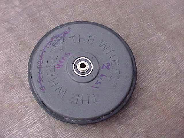
SOXW9400
Nov 29, 2004Purchek Wheel
Equipment Class
DSC - Part 15 Security/Remote Control Transmitter