SOX-W9200Remote Controlled Locking Wheel
Gatekeeper Systems, Inc.
Click to zoom
Application Details
- Equipment Class
- DXT - Part 15 Low Power Transceiver, Rx Verified
- Date of Grant
- May 09, 2007
- Application Purpose
- Original Equipment
- Date of Application
- May 09, 2007
- Equipment Note
- Remote Controlled Locking Wheel
- Frequency Range
- 2401.60000000 - 2451.80000000
- Company
- Gatekeeper Systems, Inc.
- Country
- United States
Documents & Files
Document Text
Text extracted from the exhibit documents filed with the FCC. Open a document above to read the original.
Users Manual
GATEKEEPER SYSTEMS, INC 2007 CART CONTAINMENT TRAINING MANUAL Copyright © 2007 Gatekeeper Systems, Inc. All rights reserved Gatekeeper Systems, Inc. 2007 Cart Containment Manual Rev. 01-25-07 No part of this document may be reproduced or transmitted in any form or by any means whatsoever, electronically or mechanically, including photocopying and recording, for any purpose without the express written consent of Gatekeeper Systems, Inc. Gatekeeper Systems, Inc. and the Gatekeeper Systems, Inc. logo are service marks of Gatekeeper Systems, Inc.. purchek™ is a registered trademark of Gatekeeper Systems, Inc.. Information in this document is furnished for informational use only, and is subject to change without notice and does not represent a commitment on the part of Gatekeeper Systems, Inc. Product names mentioned in this document may be trademarks or registered trademarks of their respective companies and are hereby acknowledged. All information contained herein is proprietary and confidential. G ATEKEEPER SYSTEMS INC. 2007 CART CONTAINMENT MANUAL Table Of Contents 1 Introduction ---------------------------------------------------------------------------------------------------------------------- 1 2 GS 2 System Description and Components ---------------------------------------------------------------------------- 2 3 Pre-Installation Tasks -------------------------------------------------------------------------------------------------------- 7 The Site Survey 7 Determining the CentralTransmitter Location 8 Determining System Component Requirements 8 Perimeter Antenna Configurations 9 Other Perimeter Antenna Considerations 10 Documenting the Site Survey 11 Sample Site Plans 13 Single Locking Loop 13 Double Saw Cut 14 Twisted Pair And Multiple Lockboxes 15 Single Locking Loop - Over Roof 16 Site Survey Checklist 17 4 Installation---------------------------------------------------------------------------------------------------------------------- 18 Overview 18 Required Tools and Materials 19 Arriving On Site 21 Confirming the CentralTransmitter Location 21 Marking the Antenna Path 21 Saw Cutting the Marked Area 22 Removing Saw Cut Residue 22 Installing the Perimeter Antenna 23 Sealing the Saw Cut 24 Mounting the Central Transmitter 24 CentralTransmitter Front Panel 25 CentralTransmitter Circuit Board 26 Connecting Electrical Power to the CentralTransmitter 29 Calibrating the Central Transmitter 30 Selecting the Transmitter Mode 30 Connecting the Alarm Relays 31 Information Tracker 31 Perimeter Striping 32 Installing the Parking lot Signs 34 Installing the Anti-tilt Bars 36 Installing the GS2 Wheel 36 Installing the Cart-Mounted Signs 37 5 Installation Photographs -------------------------------------------------------------------------------------------------- 38 6 ExitManager--------------------------------------------------------------------------------------------------------------------55 7 Indoor Cart Containment Systems ------------------------------------------------------------------------------------- 58 System Layout 58 System Layout with EAS System 59 8 Store Training -----------------------------------------------------------------------------------------------------------------60 Training the Store Personnel 60 GS 2 TRAINING ACKNOWLEDGEMENT AND EQUIPMENT RECEIPT FORM 61 Installation Walk Through 62 9 Communication and Documentation ---------------------------------------------------------------------------------- 64 10 Troubleshooting -------------------------------------------------------------------------------------------------------------- 65 Diagnosing CentralTransmitter and Perimeter Antenna Issues 65 Main Troubleshooting Flow Chart 66 G ATEKEEPER SYSTEMS INC. 2007 CART CONTAINMENT MANUAL Verifying Power to the CentralTransmitter 67 Checking Antenna Resistance 68 Finding a Perimeter Antenna Defect 69 Antenna Troubleshooting with a Tone Generator and Probe 70 Antenna Troubleshooting with the Tracker II 71 Troubleshooting Single Loop Installations 72 Troubleshooting Double Saw Cut and Twisted Pair with Lock Boxes 72 Replacing the Central Transmitter Fuse 72 Setting Up a Test Loop 73 Coupling 73 Mixed Wheel Environments 75 11 Material Specification Sheets -------------------------------------------------------------------------------------------- 77 14AWG Traffic Loop 78 Twisted Pair (neutral) 79 Tri-American Cold Pour 81 Cold Pour Estimating Guide 82 SealMaster Cold Pour Sealant 83 SealMaster Cold Pour Sealant 83 CrackMaster Hot Pour Applicator 85 CrackMaster Hot Pour Sealant 86 Concrete Sealant for Level Surfaces 87 Concrete Sealant for Non-Level Surfaces 89 Concrete Saw 93 Tempo Tracker II, Model 501 94 Kleen Sweep 27 96 12 Training Checklist------------------------------------------------------------------------------------------------------------ 97 Index-----------------------------------------------------------------------------------------------------------------------------------100 Introduction G ATEKEEPER SYSTEMS INC. 2007 CART CONTAINMENT MANUAL Page 1 1 Introduction Overview The purpose of this manual is to provide the reference materials, training guidelines, step-by- step instruction, and product specifications to enable the proper installation and maintenance of the GS 2 System. When combined with training from Gatekeeper Field Service Supervisors, you and your company will have a thorough understanding of all techniques required to install and service the GS 2 System. Proper knowledge of the installation and maintenance techniques that Gatekeeper employs offers your company a compelling opportunity to provide our mutual customers with value-added service and support. About Gatekeeper Gatekeeper Systems was founded in 1996 on the principles of innovation, quality, and service. Recognizing the significant impact of cart theft on retailers, Gatekeeper Systems designed and developed the industry’s preeminent cart containment system. Over the years, we’ve gaine…
Text truncated - open the document above for the full version.
Users Manual
Installation G ATEKEEPER SYSTEMS INC. 2007 CART CONTAINMENT MANUAL Page 22 Saw Cutting the Marked Area The 14AWG locking antenna is installed in asphalt or concrete in a saw cut one inch (1”) deep and one- quarter inch (1/4”) wide. Saw cutting at this depth minimizes the chances of running into drain or power transmission lines already placed in the ground, as they are required to be buried at a much lower depth. Saw cuts can be done using either a wet or dry cut technique. Dry saw cutting leaves no wet residue and is therefore easier to clean up. The downside to dry saw cutting is that it requires the proper equipment to capture the airborne dry asphalt particles. If you choose to dry cut, make sure that all technicians are equipped with proper breathing apparatus and protective gear. Wet cutting does not require respiratory protection, but requires more work to clean up. Also, residue from wet cutting must NEVER be allowed to run into the storm drain or public streets. Most cities will levy a heavy fine for this infraction. All saw-cuts on concrete should be in a cold seam, where possible. Removing Saw Cut Residue After sawing, the cut needs to be cleaned out. If you have chosen to wet cut, clean out the saw cut and surrounding area using a wet-dry shop vacuum and a high-pressure water sprayer. In order to minimize staining, make sure to clean the areas before the saw cut residue dries. If you have chosen to dry cut, clean the saw cut and surrounding area using the specified power sweeper. Any excess residues should be cleaned out using the Gatekeeper Hook, or if a Hook is not available, you may use a straight edge screwdriver. Wet / dry vacuum following saw cutter closely Gatekeeper Hook for cleaning out the saw cut Installation G ATEKEEPER SYSTEMS INC. 2007 CART CONTAINMENT MANUAL Page 23 Installing the Perimeter Antenna Once the saw cut is completed, and cleaned, the next step is to install the 14AWG antenna. Place the antenna wire spool onto a wire caddy and walk along the saw cut so that the wire rolls off the spool and into the cut. Follow with the Gatekeeper Antenna Roller to press the antenna securely down into the cut. At some point during the installation, you will need to run the perimeter antenna through landscaped areas enclosed by concrete curbs. See “Perimeter Antenna through Curbs”, page 42 for detailed instructions. Before trenching in the landscape, insure that you will not be encroaching upon any sprinkler system or electrical lines. It is imperative that any antenna placed in the landscape areas be installed in conduit, as the conduit offers corrosion, resistance and high impact protection. Take caution to insure that the antenna is installed away from sprinklers, water valves, and other high maintenance areas. User your fish tape to pull the antenna from one end of the PVC to the other end. Anytime PVC conduit is used it must be sealed where the conduit ends. Use expansion foam to seal each end of the PVC conduit after the antenna has been installed. Always return the landscape area to its original condition. When it is necessary to bring the antenna across the roofline or down the side of the building, ½” rigid conduit is used for the first ten feet (10’), than ½” EMT conduit should be installed and supported as required by code. When conduit is exposed to the elements, compression connectors must be used. Never install any antenna above ground without running it through conduit. Anytime a conduit makes contact with the ground surface, a one inch (1”) penetration must be made and repaired with the appropriate patch, i.e. concrete or asphalt. If the conduit contacts the earth, the conduit must be no less than six inches (6”) deep. Use expansion foam to seal the ends of conduit when installing below ground. When EMT is installed on a roofline, 2” x 4” wood blocks must be used to support the conduit. Use mastic to affix the blocks to the roof. Never nail or screw the wood blocks to the roof. The roof surface should never be penetrated. For detailed instructions on making splices in the perimeter antenna, see 46. Installation G ATEKEEPER SYSTEMS INC. 2007 CART CONTAINMENT MANUAL Page 24 Sealing the Saw Cut After the antenna is in place, the remaining ¾” of the saw cut is filled with asphalt sealer. The environment of the installation will dictate the type of sealer to use. In dry weather conditions of 40º Fahrenheit or higher, a cold-pour sealant and pour pot should be used. Gatekeeper approved sealants for asphalt include OverKote and SealMaster. Gatekeeper approved sealants for concrete include SikaFlex or Vulcum. Make sure that you have completely cleaned the surface of the asphalt before applying sealer. When using cold pour asphalt sealant, mix the sealer thoroughly before attempting to apply. Use an electric drill with a mixing paddle for at least five (5) minutes to guarantee that it is thoroughly mixed. To insure a professional looking installation, make sure that the sealant is level with the top of the saw cut (see diagram). If any settling, sags, or cracks develop during the curing process, a second application will be required. While applying the sealer into the saw cut, if there is any excess or over spill, use a V- shaped squeegee to direct the excess into the saw cut and to obtain an even application. It is advisable to use traffic cones and caution tape to prevent any vehicle or customer traffic from crossing the sealer for approximately 30 minutes while it is drying. It takes approximately 24 hours for cold pour sealer to completely cure. Cold pour sealant may not be used at temperatures below 40º Fahrenheit or in wet conditions. If cold or wet weather does not permit the use of a cold pour sealant, than a hot melt asphalt sealant will be required. For hot melt installations, you will need a melting applicator, a heat lance, and hot pour crack sealant. It is important to note that if the temperature is less than 40º Fahrenheit, you must use a heat lan…
Text truncated - open the document above for the full version.
Users Manual
Installation Photographs G ATEKEEPER SYSTEMS INC. 2007 CART CONTAINMENT MANUAL Page 47 5. Apply some Oatey tinning flux to the joint. 6. Heat the joint with a soldering torch. 7. When hot enough, remove the torch and touch the solder to the joint. If hot enough, the solder will flow through and around the strands. Soldering the splice 8. Once the joint has cooled, apply ScotchKote to the soldered connection. Applying ScotchKote sealer Installation Photographs G ATEKEEPER SYSTEMS INC. 2007 CART CONTAINMENT MANUAL Page 48 9. Slide the heat shrink tubing back over the joint so that the tubing extends about an inch past the cut insulation on each end. 10. Use the torch to shrink the tubing tightly around the joint. Splice before heating the shrink tube Sealing the Saw Cuts Before sealing, mix the cold-pour asphalt sealant thoroughly, using a drill and mixing wand Use the SealMaster Cold-Pour Pot to apply the sealer in an even manner. Installation Photographs G ATEKEEPER SYSTEMS INC. 2007 CART CONTAINMENT MANUAL Page 49 Asphalt sealant being poured. The pour pot is pulled, not pushed along the cut. The finished product. Installation Photographs G ATEKEEPER SYSTEMS INC. 2007 CART CONTAINMENT MANUAL Page 50 Sealing Concrete Whenever possible, use existing expansion joints for cutting in concrete. This speeds the job and saves wear and tear on the saw blade. Seal with a self-leveling sealer such as QuikRete or SikaFlex, designed especially for use on concrete. DO NOT use asphalt sealer on concrete. Always fill the cut completely with sealer. Any gaps will settle and become water collectors. Installation Photographs G ATEKEEPER SYSTEMS INC. 2007 CART CONTAINMENT MANUAL Page 51 Installing Parking Lot Signs “Attention Shopper” signs must be installed with the bottom of the sign at least 7 feet above the ground. This will require two pieces of 6 foot long U-channel, bolted together. The signs should be installed at the very top of the U-channel with the back of the sign against the wide (flared) side of the U-channel. Two pieces of 6 foot U-channel bolted together To ensure the safety of store patrons, the bottom of the sign should be at least seven (7) feet above the ground. Installation Photographs G ATEKEEPER SYSTEMS INC. 2007 CART CONTAINMENT MANUAL Page 52 Setting the Sign Posts Use QuikRete fast setting concrete mix to anchor the sign posts into the landscaping. Set the post into the hole and pour the dry QuikRete evenly around the base. Pour water into the hole and mix. Make sure to keep the post absolutely vertical while the QuikRete sets up. Installation Photographs G ATEKEEPER SYSTEMS INC. 2007 CART CONTAINMENT MANUAL Page 53 Containment Zone Striping Striping should be placed approximately three feet from the antenna line (indicated by the chalk line in the photo below). Block off the area with traffic cones to prevent automobile traffic from crossing over the stripe until it is dry. Use masking tape, placed nine inches (9”) apart. This will ensure a clean, straight stripe. Use a nine-inch (9”), ¾” NAP paint roller to apply the yellow traffic paint. Installation Photographs G ATEKEEPER SYSTEMS INC. 2007 CART CONTAINMENT MANUAL Page 54 Painting the Stencils A blowtorch can be used to cut down the drying time. Center the shopping cart stencil on the stripe and paint with black traffic paint. Stencils should be spaced approximately five feet (5’) apart. A finished stripe with stencils. ExitManager G ATEKEEPER SYSTEMS INC. 2007 CART CONTAINMENT MANUAL Page 55 6 ExitManager ExitManager Front Panel ExitManager G ATEKEEPER SYSTEMS INC. 2007 CART CONTAINMENT MANUAL Page 56 ExitManager – Inside Case ExitManager G ATEKEEPER SYSTEMS INC. 2007 CART CONTAINMENT MANUAL Page 57 ExitManager Settings ExitManager can be configured to generate a signal for a Standard Outdoor GS 1 application, a Standard Indoor GS1 application, or a Standard Indoor Purchek application, based on the settings of the Signal Selector switches shown in the tables below. Selector Switch Settings: 1 ▲ 2 ▲ 3 ▼ 4 ▼ 5 ▼ 6 ▼ Outdoor GS 2 Application (One locking line) Cable Termination Settings: • Locking Antenna terminates at the “Register Line” Loop Connector • Jumper Is Inserted into the Cable Inputs at the “Door Line” Loop Connector Rotary Switch Setting: 1 Selector Switch Settings: 1 ▲ 2 ▼ 3 ▲ 4 ▼ 5 ▼ 6 ▼ Indoor GS 2 Application (One lock line and one unlock line) Cable Termination Settings: • Locking Antenna terminates at the “Register Line” Loop Connector • Unlocking Antenna Terminates at the “Door Line” Loop Connector Rotary Switch Setting: 0 Selector Switch Settings: 1 ▼ 2 ▼ 3 ▼ 4 ▼ 5 ▼ 6 ▼ Indoor Purchek Application Cable Termination Settings: • Locking Antenna terminates at the “Door Line” Loop Connector • Unlocking Antenna Terminates at the “Register Line” Loop Connector Rotary Switch Settings to set Entry Permission Timings (Setting – Timing) • 0 - 2 minutes • 1 - 15 minutes • 2 - 10 minutes • 3 - 30 minutes • 4 - 1 hour • 5 - 3 hours • 6 - 2 hours • 7 - 1 minute Indoor Cart Containment Systems G ATEKEEPER SYSTEMS INC. 2007 CART CONTAINMENT MANUAL Page 58 7 Indoor Cart Containment Systems System Layout Using the ExitManager in combination with 22AWG antenna, it is possible to configure a cart containment system at the interior of a store’s exit. Often times these systems are configured to provide an unlocking loop, in addition to a locking loop. This additional loop allows customers and store personnel to pull a locked shopping cart backwards two to three feet and unlock the wheel, eliminating the need for a store attendant with a Cartkey. The antenna of an indoor system is generally embedded into the concrete slab below the carpet or vinyl-covered tile, or sometimes, in the grout lines of a ceramic tile floor surface. For systems where there is no electronic article surveillance (EAS) system in place, each loop or lock box should be configured to be two-feet wide, with a minimum of four-feet of separation between the two …
Text truncated - open the document above for the full version.
Users Manual
Material Specification Sheets G ATEKEEPER SYSTEMS INC. 2007 CART CONTAINMENT MANUAL Page 82 Cold Pour Estimating Guide Material Specification Sheets G ATEKEEPER SYSTEMS INC. 2007 CART CONTAINMENT MANUAL Page 83 SealMaster Cold Pour Sealant Material Specification Sheets G ATEKEEPER SYSTEMS INC. 2007 CART CONTAINMENT MANUAL Page 84 SealMaster Cold Pour (cont.) Material Specification Sheets G ATEKEEPER SYSTEMS INC. 2007 CART CONTAINMENT MANUAL Page 85 CrackMaster Hot Pour Applicator Material Specification Sheets G ATEKEEPER SYSTEMS INC. 2007 CART CONTAINMENT MANUAL Page 86 CrackMaster Hot Pour Sealant Material Specification Sheets G ATEKEEPER SYSTEMS INC. 2007 CART CONTAINMENT MANUAL Page 87 Concrete Sealant for Level Surfaces Material Specification Sheets G ATEKEEPER SYSTEMS INC. 2007 CART CONTAINMENT MANUAL Page 88 Concrete Sealant for Level Surfaces (cont.) Material Specification Sheets G ATEKEEPER SYSTEMS INC. 2007 CART CONTAINMENT MANUAL Page 89 Concrete Sealant for Non-Level Surfaces Material Specification Sheets G ATEKEEPER SYSTEMS INC. 2007 CART CONTAINMENT MANUAL Page 90 Concrete Sealant for Non-Level Surfaces (cont.) Material Specification Sheets G ATEKEEPER SYSTEMS INC. 2007 CART CONTAINMENT MANUAL Page 91 3M ScotchKote Electrical Coating Material Specification Sheets G ATEKEEPER SYSTEMS INC. 2007 CART CONTAINMENT MANUAL Page 92 3M ScotchKote Electrical Coating (cont.) Material Specification Sheets G ATEKEEPER SYSTEMS INC. 2007 CART CONTAINMENT MANUAL Page 93 Concrete Saw Material Specification Sheets G ATEKEEPER SYSTEMS INC. 2007 CART CONTAINMENT MANUAL Page 94 Tempo Tracker II, Model 501 Material Specification Sheets G ATEKEEPER SYSTEMS INC. 2007 CART CONTAINMENT MANUAL Page 95 Tempo Tracker II, Model 501 (cont.) Material Specification Sheets G ATEKEEPER SYSTEMS INC. 2007 CART CONTAINMENT MANUAL Page 96 Kleen Sweep 27 Training Checklist G ATEKEEPER SYSTEMS INC. 2007 CART CONTAINMENT MANUAL Page 97 12 Training Checklist Technician: Training Location: Gatekeeper Cart Containment System Concept and Functionality • System Components (Wheels, Antenna, Transmitter, CartKey, Site Management) • Perimeter Based System – closed loop • Store Personnel Training Date: Completed: Yes No Site Survey and System Layout • Survey Checklist • Site Plan (Key Measurements, Antenna Type, Transmitter Location, Sign Location) • Single Loop Enclosed Perimeter (Sample Site Plans) • Double Saw Cut (Sample Site Plans) • Over Roof (Sample Site Plans) • Multiple Lockbox and Twisted Pair (Sample Site Plans) • Photograph Locations • Drawing the Site Plan (Key Measurements, Transmitter and Sign Locations) Date: Completed: Yes No Materials Specifications • Antenna Specifications (14G Traffic Cable, 14G Twisted Pair, 20G Antenna) • Sealer and Pour Pot Specifications (OverKote & SealMaster) • Antenna Splicing Specifications • Concrete Saw Specifications • Striping and Signage Specifications • Tool List Date: Completed: Yes No Cart Containment System Installation • Installation Preparation • Arrive on site and check in with store management • Confirm/determine the CentralTransmitter location • Mark the perimeter area for the saw cut Date: Completed: Yes No Training Checklist G ATEKEEPER SYSTEMS INC. 2007 CART CONTAINMENT MANUAL Page 98 System Installation • Saw cut the marked area • Clean the saw cut • Install the 14G locking line and twisted pair (use antenna specified in “Materials”) • Splice the sections of antenna together • Seal the saw cut (use pour pot and sealer specified in “Materials”) • Mount the CentralTransmitter • Measure and document antenna resistance (multi-meter required) • Connect electrical power to the CentralTransmitter • Calibrating the CentralTransmitter • Connecting Alarm Relays to the CentralTransmitter • Install the Parking Lot Signs • Perimeter Striping Date: Completed: Yes No Cart Installation • Install the anti-tilt bar • Install the Gatekeeper Wheel • Install the Cart-Mounted Signs Date: Completed: Yes No Store Training • Train the store personnel • Document store training Date: Completed: Yes No Training Checklist G ATEKEEPER SYSTEMS INC. 2007 CART CONTAINMENT MANUAL Page 99 Training Checklist - System Troubleshooting Wheel Troubleshooting • Determine the wheel type by revision code • Potential failure modes and troubleshooting them • Cart out-of-balance Date: Completed: Yes No Central Transmitter Troubleshooting • Potential failure modes (visual alarm indicators) Date: Completed: Yes No Antenna Troubleshooting • Visual inspection of the perimeter line • Use of a Tone Generator (see Tool List) to find the break • Dividing the antenna to find the break • Proper splicing technique Date: Completed: Yes No Signal Coupling • Explanation of signal coupling and possible causes • Try to replicate the coupling • Using a signal tester to look for extranious noise • Solutions to eliminate coupling Date: Completed: Yes No Product Specifications • W-9455 GS 2 Wheel • D-9110 CentralTransmitter • D-9500 ExitManager • K-9500 CartKey Date: Completed: Yes No I certify that the technician named below has completed the Gatekeeper Systems Inc. Field Service Training Program and has been presented with the related coursework and training materials. Technician: Trainer: Date: G ATEKEEPER SYSTEMS INC. 2007 CART CONTAINMENT MANUAL Page 100 Index A alarm relays, 30 analog mode, 29 Anixter cable, 77 antenna alert relay, 30 antenna roller, 39 anti tilt bars, 35 audible alarm switch, 24 B Belden cable, 78, 79 C cart mounted signs, 36 CartKey, 5 Carttronics Caster, 29 caution tape, 37 CentralTransmitter calibrating, 29 circuit board, 25 connecting power supply, 28 description, 4 determing location for, 7 front panel, 24 installing, 20 mounting, 23 power LED, 24 replacing the fuse, 71 system alert LED, 24 verifying power to, 66 cold pour estimating guide, 81 concrete saw along expansion joints, 49 sealant for non-level surfaces, 88, 89 sealing, 49 self-leveling sealant, 86, 87 concrete saw, 38, 92 conduit, install…
Text truncated - open the document above for the full version.
Cover Letter(s)
Scott McCutchan From: Scott McCutchan [[email protected]] Sent: Friday, April 13, 2007 12:49 PM To: '[email protected]' Cc: '[email protected]' Subject: FCC ID: SOX-W9200 - (15.249) 4/13/2007 Mr. Fujimoto: In order for processing of this certification application (FCC ID: SOX-W9200 – (15.249)) to continue, the following issue(s) will have to be addressed: 1) Please provide a current, signed TCB contract 2) The letter of authority must be addressed to CETCB, and not the FCC 3) The user’s manual must contain the information contained in section 15.21 of the FCC rules, cautioning the user that modifications not approved by the manufacturer may void the user’s authority to operate the equipment. The item(s) indicated above must be submitted before processing can continue on the above referenced application. Failure to provide the requested information within 60 days of the original e-mail date may result in application dismissal and forfeiture of the filing fee. Also, please note that partial responses increase processing time and should not be submitted. Please upload responses and/or exhibits to the electronic filing website. Your correspondence number is SOX-W9200 – (15.249)-1. Best regards, Scott McCutchan Operations Manager Compatible Electronics TCB
Cover Letter(s)
Correspondence by Project Project Number: Correspondence NumberMemo SOX-9200 -- (15.249)-1 1. The Current TCB Contract has been uploaded. 2. The Letter of Authority has been revised and uploaded 3. The user's manual has been revised and the appropriate part where the revision took place has been uploaded. 1167872613
Test Report
Report Number: B61009D1 FCC Part 15 Subpart B and FCC Section 15.249 Test Report Remote Controlled Locking Wheel Model: W-9200 Brea Division 114 Olinda Drive Brea, CA 92823 (714) 579-0500 Agoura Division 2337 Troutdale Drive Agoura, CA 91301 (818) 597-0600 Silverado Division 19121 El Toro Road Silverado, CA 92676 (949) 589-0700 Lake Forest Division 20621 Pascal Way Lake Forest, CA 92630 (949) 587-0400 Page 1 of 15 FCC PART 15, SUBPART B and C TEST REPORT for REMOTE CONTROLLED LOCKING WHEEL MODEL: W-9200 Prepared for GATEKEEPER SYSTEMS, INC. 8 STUDEBAKER IRVINE, CALIFORNIA 92618 Prepared by:_____________________ KYLE FUJIMOTO Approved by:____________________ JAMES ROSS COMPATIBLE ELECTRONICS INC. 114 OLINDA DRIVE BREA, CALIFORNIA 92823 (714) 579-0500 DATE: OCTOBER 20, 2006 REPORT APPENDICES TOTAL BODY A B C D E PAGES 15 2 2 2 14 11 46 This report shall not be reproduced except in full, without the written approval of Compatible Electronics. Report Number: B61009D1 FCC Part 15 Subpart B and FCC Section 15.249 Test Report Remote Controlled Locking Wheel Model: W-9200 Brea Division 114 Olinda Drive Brea, CA 92823 (714) 579-0500 Agoura Division 2337 Troutdale Drive Agoura, CA 91301 (818) 597-0600 Silverado Division 19121 El Toro Road Silverado, CA 92676 (949) 589-0700 Lake Forest Division 20621 Pascal Way Lake Forest, CA 92630 (949) 587-0400 Page 2 of 15 TABLE OF CONTENTS Section / Title PAGE GENERAL REPORT SUMMARY 4 SUMMARY OF TEST RESULTS 4 1. PURPOSE 5 2. ADMINISTRATIVE DATA 6 2.1 Location of Testing 6 2.2 Traceability Statement 6 2.3 Cognizant Personnel 6 2.4 Date Test Sample was Received 6 2.5 Disposition of the Test Sample 6 2.6 Abbreviations and Acronyms 6 3. APPLICABLE DOCUMENTS 7 4. DESCRIPTION OF TEST CONFIGURATION 8 4.1 Description Of Test Configuration - EMI 8 4.1.1 Cable Construction and Termination 9 5. LISTS OF EUT, ACCESSORIES AND TEST EQUIPMENT 10 5.1 EUT and Accessory List 10 5.2 EMI Test Equipment 11 6. TEST SITE DESCRIPTION 12 6.1 Test Facility Description 12 6.2 EUT Mounting, Bonding and Grounding 12 7. TEST PROCEDURES 13 7.1 RF Emissions 13 7.1.1 Radiated Emissions (Spurious and Harmonics) Test 13 7.1.2 Radiated Emissions (Spurious and Harmonics) Test (Continued) 14 8. CONCLUSIONS 15 Report Number: B61009D1 FCC Part 15 Subpart B and FCC Section 15.249 Test Report Remote Controlled Locking Wheel Model: W-9200 Brea Division 114 Olinda Drive Brea, CA 92823 (714) 579-0500 Agoura Division 2337 Troutdale Drive Agoura, CA 91301 (818) 597-0600 Silverado Division 19121 El Toro Road Silverado, CA 92676 (949) 589-0700 Lake Forest Division 20621 Pascal Way Lake Forest, CA 92630 (949) 587-0400 Page 3 of 15 LIST OF APPENDICES APPENDIX TITLE A Laboratory Recognitions B Modifications to the EUT C Additional Models Covered Under This Report D Diagrams, Charts, and Photos • Test Setup Diagrams • Radiated Emissions Photos • Antenna and Effective Gain Factors E Data Sheets LIST OF FIGURES FIGURE TITLE 1 Plot Map And Layout of 3 Meter Radiated Site Report Number: B61009D1 FCC Part 15 Subpart B and FCC Section 15.249 Test Report Remote Controlled Locking Wheel Model: W-9200 Brea Division 114 Olinda Drive Brea, CA 92823 (714) 579-0500 Agoura Division 2337 Troutdale Drive Agoura, CA 91301 (818) 597-0600 Silverado Division 19121 El Toro Road Silverado, CA 92676 (949) 589-0700 Lake Forest Division 20621 Pascal Way Lake Forest, CA 92630 (949) 587-0400 Page 4 of 15 GENERAL REPORT SUMMARY This electromagnetic emission test report is generated by Compatible Electronics Inc., which is an independent testing and consulting firm. The test report is based on testing performed by Compatible Electronics personnel according to the measurement procedures described in the test specifications given below and in the "Test Procedures" section of this report. The measurement data and conclusions appearing herein relate only to the sample tested and this report may not be reproduced without the written permission of Compatible Electronics, unless done so in full. This report must not be used to claim product endorsement by NVLAP, NIST or any other agency of the U.S. Government. Device Tested: Remote Controlled Locking Wheel Model: W-9200 S/N: N/A Product Description: See Expository Statement Modifications: The EUT was not modified in order to meet the specifications. Customer: Gatekeeper Systems, Inc. 8 Studebaker Irvine, California 92618 Test …
Text truncated - open the document above for the full version.
Contact Information
Applicant
Steve Hannah(Vice President, Engineering)
Technical Contact
Compatible ElectronicsKyle Fujimoto
[email protected]714-579-0500
114 Olinda Drive · Brea, California · United States
Test Firm
Compatible Electronics, Inc.Ruby Hall
[email protected]805-480-4044
Technical Specifications
| # | Rule Parts | Frequency Range | Power Output |
|---|---|---|---|
| 1 | 15C | 2.40 GHz - 2.45 GHz | - |
Other Applications from Gatekeeper Systems, Inc.

SOX-E65400
Feb 02, 2010CM Receiver
Equipment Class
DXT - Part 15 Low Power Transceiver, Rx Verified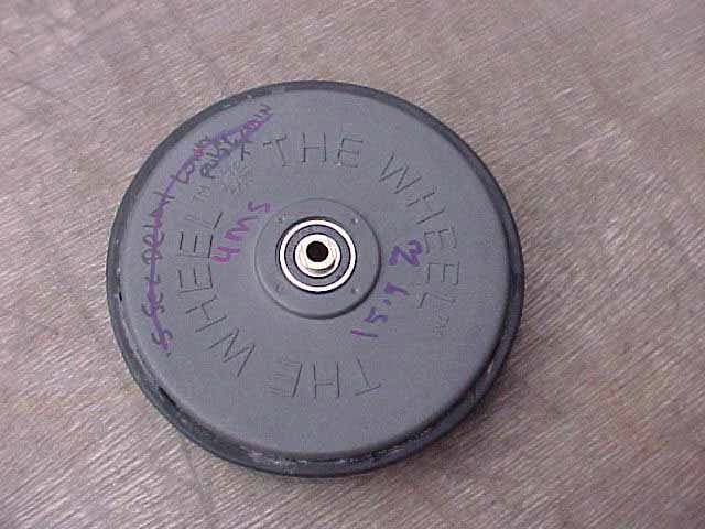
SOXW9400
Nov 29, 2004Purchek Wheel
Equipment Class
DSC - Part 15 Security/Remote Control Transmitter