SPBMX1KDCT24DECT point of sales terminal
Axalto SA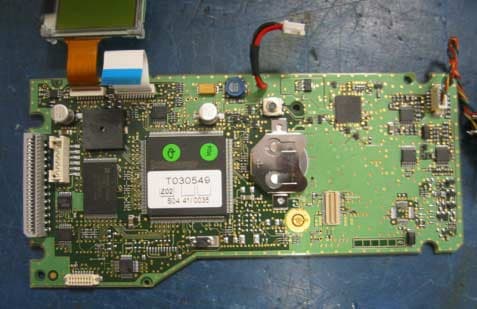
Click to zoom
Application Details
- Equipment Class
- DSS - Part 15 Spread Spectrum Transmitter
- Date of Grant
- Oct 11, 2005
- Application Purpose
- Original Equipment
- Date of Application
- Oct 11, 2005
- Equipment Note
- DECT point of sales terminal
- Frequency Range
- 2401.05600000 - 2482.27200000
- Company
- Axalto SA
- Country
- France
Documents & Files
Document Text
Text extracted from the exhibit documents filed with the FCC. Open a document above to read the original.
Users Manual
MagIC X1000 DECT Axalto – 2005 1 Installation Guide Guide d’installation Guida per l’installazione Guía de instalación Point of Sales Terminals / Terminaux de paiements / Terminali di pagamento / Terminales Punto de Venta MagIC X1000 DECT Axalto – 2005 2 ß Before first use: charge the battery for at least 3H. Base and handset must be associated for a correct charging. ß Avant première utilisation : Charger la batterie pendant au moins 3H. La base et le terminal doivent être associé pour une charge correcte. ß Prima di utilizzare il terminale per la prima volta: caricare la batteria per almeno 3H. Per una corretta carica della batteria la base di riposo e il terminale portatile devono essere uniti ß Antes primero el uso: carga la batería para por lo menos 3H. La base y el terminal deben asociarse para una carga correcta. Content / Contenu / Contenuto / Contenido Terminal handset & Docking station Terminal portable et sa base Terminale portatile & Base di riposo Terminal portátil & Base Battery Batterie Batteria Batería Paper roll Rouleau de papier Carta stampantina Papel de impresora Phone line cable Cable telephone Cavo telefonico Cable de la línea del telefono Power supply Alimentation Blocco d’alimentazione Fuente de alimentación Option / Option / Opzione / Opcion 2 nd CAM reader 2 nd lecteur CAM 2 ° lettore CAM 2 nd CAM lector MagIC X1000 DECT Axalto – 2005 3 FCC Statement The United States Federal Communications Commission (in 47 CFR 15.105) has specified that the following notice be brought to the attention of users of this product: This equipment has been tested and found to comply with the limits for a Class B digital device, pursuant to part 15 of the FCC Rules. These limits are designed to provide reasonable protection against harmful interference in a residential installation. This equipment generates, uses and can radiate radio frequency energy and, if not installed and used in accordance with the instructions, may cause harmful interference to radio communications. However, there is no guarantee that interference will not occur in a particular installation. If this equipment does cause harmful interference to radio or television reception, which can be determined by turning the equipment off and on, the user is encouraged to try to correct the interference's by one or more of the following measures: ß Reorient or relocate the receiving antenna. ß Increase the separation between the equipment and the receiver. ß Connect the equipment into an outlet on a circuit different from that to which the receiver is connected. ß Consult the dealer or an experienced radio/TV technician for help. The user may find the following booklet, prepared by the Federal Communications Commission, helpful: How to identify et Resolve Radio/TV Interference Problems. This booklet is available from the U.S. Government Printing Office, Washington, D.C. 20402, Stock No. 004-000-00345-4. Pursuant to Part 15.21 of the FCC Rules, any changes or modifications to this equipment not expressly approved by Axalto may cause, harmful interference and void the FCC authorization to operate this equipment. WARNING: To prevent fire or shock hazard and damage to your unit, do not expose this terminal to rain or moisture. TO REDUCE THE RISK OF ELECTRIC SHOCK, DO NOT REMOVE COVER (OR BACK). NO USER SERVICEABLE PARTS INSIDE. REFER SERVICING TO QUALIFIED SERVICE PERSONNEL. For your permanent record, we urge you to record the serial number of your terminal in the space provided below. The serial number is located on the label, which can be found on the bottom of the unit. Terminal Serial Number________________________________ Consumer information & FCC Requirements This equipment complies with Part 68 of the FCC rules. On the back of this equipment is a label that contains, among other information, the FCC registration number and Ringer Equivalence Number (REN) for this equipment. If requested, provide information to your telephone company. ß The REN is useful to determine the quantity of devices you may connect to your telephone and still have all of those devices ring when your number is called. In most, but not all areas, the sum of the 'REN's of all devices should not exceed five (5.0). To be certain of the number of devices you may connect to your line, as determined by the REN, you should call your local telephone company to determine the maximum REN for your calling area. ß If your MagIC X1000 causes harm to the telephone network, the Telephone Company may discontinue your service temporarily. If possible, they will notify you in advance. But if advance notice isn't practical, you will be notified as soon as possible. You will be advised of your right to file a complaint with the FCC. ß Your telephone company may make changes in its facilities, equipment, operations, or procedures that could affect the proper operation of your equipment. If they do, you will be given advance notice so as to give you an opportunity to maintain uninterrupted service. ß If you experience trouble with this equipment, MagIC X1000, please contact Axalto Canada Inc, Maintenance Center, 620 rue Cathcart , Suite 864, Montreal, Quebec, H3B 1M1, Canada – Fax: 1 514 879 1482, for repair/warranty information. The telephone company may ask you to disconnect this equipment from the network until the problem has been corrected or you are sure that the equipment is not malfunctioning. ß There are no repairs that can be made by the customer to the MagIC X1000. ß This equipment may not be used on coin service provided by the telephone company. Connection to party lines is subject to state tariffs. (Contact your state public utility commission or corporation commission for information). Warranty and Return Information ß Limited warranty Axalto warrants its hardware products against defects in materials and workmanship to the original purchaser for a period of one (1) year from the date of shipment. Warranty service, whether it is repair, adjustment or rep…
Text truncated - open the document above for the full version.
External Photos
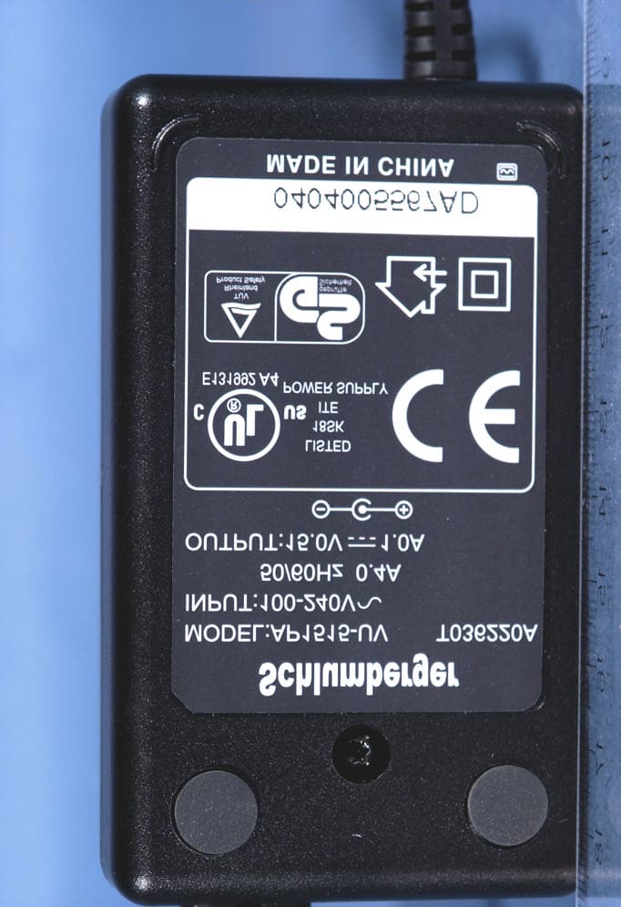
EQUIPMENT FCC ID : S PBMX1KDCT24 Ex h i bi t 2 EXTERNAL PHOTOS Page : 1/2 Written by : O. ROY June 29, 2005 Test report # : 21201-01-CC-1 -a 1.2 PRO DUCT PICTURES : Power supp ly Schlumber ger M odel AP14515-UV T03622A EQUIPMENT FCC ID : S PBMX1KDCT24 Ex h i bi t 2 EXTERNAL PHOTOS Page : 2/2 Written by : O. ROY June 29, 2005 Test report # : 21201-01-CC-1 -a Alternative p ower supp ly : SCEPTRE N° PD1210APL06
ID Label/Location Info
EQUIPMENT FCC ID : S PBMX1KDCT24 Ex h i bi t 1 FCC ID LABEL Page : 1/2 Written by : O. ROY June 29, 2005 Test report # : 21201-01-CC-1 -a 1 RODUC T LAB ELLING 1.1 FC C ID LAB EL AN D LOCATION EQUIPMENT FCC ID : S PBMX1KDCT24 Ex h i bi t 1 FCC ID LABEL Page : 2/2 Written by : O. ROY June 29, 2005 Test report # : 21201-01-CC-1 -a
Internal Photos
EQUIPMENT FCC ID : S PBMX1KDCT24 Exhibit 2b INTERNAL PHOTOS Page : 1/12 Written by : O. ROY June 29, 2005 Test report # : 21201-01-CC-1 -a 1.2 DEC T MO DULE DETAILS : 1.2.1 NS RADIO MODULE SC14CVM2.4R4C1 PHOTOG RAPHS : 1.2.1.1 Top view 1.2.1.2 Bottom view EQUIPMENT FCC ID : S PBMX1KDCT24 Exhibit 2b INTERNAL PHOTOS Page : 2/12 Written by : O. ROY June 29, 2005 Test report # : 21201-01-CC-1 -a 1.2.1.3 Top view without shielding cover EQUIPMENT FCC ID : S PBMX1KDCT24 Exhibit 2b INTERNAL PHOTOS Page : 3/12 Written by : O. ROY June 29, 2005 Test report # : 21201-01-CC-1 -a 1.3 PORTAB LE DEVICE DETAILS : 1.3.1 (TOP COVER REMOVED) LCD DISPLAY Mother board (CPU) Solder side, showing the Keys locations *3 SIMM* board EQUIPMENT FCC ID : S PBMX1KDCT24 Exhibit 2b INTERNAL PHOTOS Page : 4/12 Written by : O. ROY June 29, 2005 Test report # : 21201-01-CC-1 -a 1.3.2 ALL B OAR DS G EN ERA L VU E EQUIPMENT FCC ID : S PBMX1KDCT24 Exhibit 2b INTERNAL PHOTOS Page : 5/12 Written by : O. ROY June 29, 2005 Test report # : 21201-01-CC-1 -a 1.3.3 3 SIMM B OAR D COMPONENTS VIEW 1.3.4 3 SIMM B OAR D SOLDER SI DE VI EW EQUIPMENT FCC ID : S PBMX1KDCT24 Exhibit 2b INTERNAL PHOTOS Page : 6/12 Written by : O. ROY June 29, 2005 Test report # : 21201-01-CC-1 -a 1.3.5 CPU BOARD SOLDER SI DE NIMH intreface bord CVM interface board with DECT module Antenna S mart card read er Board P rinting head and mechanism CPU board EQUIPMENT FCC ID : S PBMX1KDCT24 Exhibit 2b INTERNAL PHOTOS Page : 7/12 Written by : O. ROY June 29, 2005 Test report # : 21201-01-CC-1 -a 1.3.6 CPU BOARD COMPONENT SIDE EQUIPMENT FCC ID : S PBMX1KDCT24 Exhibit 2b INTERNAL PHOTOS Page : 8/12 Written by : O. ROY June 29, 2005 Test report # : 21201-01-CC-1 -a 1.3.7 CVM INTERFACE BOARD WITH DEC T MODU LE Antenna DECT Module EQUIPMENT FCC ID : S PBMX1KDCT24 Exhibit 2b INTERNAL PHOTOS Page : 9/12 Written by : O. ROY June 29, 2005 Test report # : 21201-01-CC-1 -a 1.3.8 SMART CARD READER BOARD 1.3.9 NIMH INTERFACE BOARD EQUIPMENT FCC ID : S PBMX1KDCT24 Exhibit 2b INTERNAL PHOTOS Page : 10/12 Written by : O. ROY June 29, 2005 Test report # : 21201-01-CC-1 -a 1.3.10 BATTERIES AND MAGNETIC READER EQUIPMENT FCC ID : S PBMX1KDCT24 Exhibit 2b INTERNAL PHOTOS Page : 11/12 Written by : O. ROY June 29, 2005 Test report # : 21201-01-CC-1 -a 1.4 BA SE DEVI C E DETA I LS : Mother board with CVM interface board with DECT module CVM interface board with DECT module EQUIPMENT FCC ID : S PBMX1KDCT24 Exhibit 2b INTERNAL PHOTOS Page : 12/12 Written by : O. ROY June 29, 2005 Test report # : 21201-01-CC-1 -a Mother board solder side
Test Report
T he reproduction of this document is authorised only if integral. Any partial reproduction must be authorised by GYL T echnologies. T his document results of test applied on one sample. It doesn’t prejudge of conformity of all products to the tested sample. GYL tech n ologies Parc d’activités de Lanserre 21 rue de la Fuye 49610 JUIGNE SUR LOIRE FRANCE T el. : +33 (0) 2.41.57.57.40 Fax : +33 (0) 2.41.45.25.77 TEST REPORT According to CFR 47 Part 15 MagIC X1000 DECT 2.4 N°21201-01-CC-1-A FCC CERTIFICATION TEST REPORT EQUIPMENT FCC ID : S PBMX1KDCT24 T he 31 pages of this report are not sharable 2 Identification : Exhibit 3 Test report Revision : a FCC registration # 90469 This report concerns : Original grant ! !! ! Class II change Equipment tested : MagIC X1000 DECT 2.4 Equipment FCC ID : S PBMX1KDCT24 D e s i gn e d by : AXALTO S .A. 50 Avenue Jean Jaurès 92120 MONTROUGE Manufacture d by : AXALTO S .A. 50 Avenue Jean Jaurès 92120 MONTROUGE Deferred grant requested p er 47 CFR 0.457 (d)(1)(ii) YES N O ! !! ! if y es, defer until : Comp any Named agrees to notify the Commission by : of the intended date of announcement of the p roduct so that the grant can be issued on the date Transition rules requested p er 15.37? YES N O ! !! ! If no, assumed Part 15, Subp art B for intentional or unintentional radiator The new 47 CFR [10-1-96 edition] p rovision FCC CERTIFICATION TEST REPORT EQUIPMENT FCC ID : S PBMX1KDCT24 T he 31 pages of this report are not sharable 3 Identification : Exhibit 3 Test report Revision : a FCC registration # 90469 S umma ry 1 REFERENCE AND RECORD OF REVISIONS OF THE TEST REPORT :.......................................... 4 2 INTERPRETATION AND REMARKS :.............................................................................................. 4 2.1 RESULTS :........................................................................................................................................................................................ 4 3 GENERAL INFORMATION : ............................................................................................................ 5 3.1 APPLICANT :.................................................................................................................................................................................. 5 3.2 MANUFACTURER :........................................................................................................................................................................ 5 3.3 TEST DATE : ................................................................................................................................................................................... 5 3.4 TEST SITE :...................................................................................................................................................................................... 5 4 INTRODUCTION :............................................................................................................................ 6 5 MEASUREMENT EQUIPMENT LIST :............................................................................................. 6 6 EXERCISING TEST CONDITIONS :................................................................................................. 8 6.1 For § 8 : Measurements according to §15.207 and 15.209 of FCC CFR 47.................................................................................... 8 6.2 For § 9 : Measurements according to §15.107 and 15.109 of FCC CFR 47.................................................................................... 8 7 CONFORMANCE STATEMENT :...................................................................................................... 8 7.1 STANDARDS REFERENCED FOR THIS REPORT :................................................................................................................... 8 7.2 JUSTIFICATION : ........................................................................................................................................................................... 8 8 TEST ACCORDING TO CFR 47 PART 15.......................................................................................... 9 8.1 REFERENCE DOCUMENTATION : ............................................................................................................................................. 9 8.2 POWER LINE CONDUCTED EMISSIONS MEASUREMENTS (15.207): ................................................................................ 9 8.3 RESULTS :........................................................................................................................................................................................ 9 8.4 INTERPRETATION AND REMARKS :...................................................................................................................................... 11 8.5 INTERPRETATION AND REMARKS :...................................................................................................................................... 13 8.6 RADIATED EMISSIONS MEASUREMENTS (15.209): ............................................................................................................ 14 8.7 RESULTS (Class B):....................................................................................................................................................................... 15 8.8 INTERPRETATION AND REMARKS :...................................................................................................................................... 18 9 TEST ACCORDING TO CFR 47 PART 15 WITH ALL ITE FUNCTIONS ACTIVATED:................... 19 9.1 REFERENCE DOCUMENTATION : ........................................................................................................................................... 19 9.2 CONDUCTED EMISSIONS MEASUREMENTS :...............................................................................…
Text truncated - open the document above for the full version.
Test Setup Photos
EQUIPMENT FCC ID : S PBMX1KDCT24 Ex h i bi t 5 TEST SET UP PHOTOS Page : 1/4 Written by : O. ROY June 29, 2005 Test report # : 21201-01-CC-1 -a CONDUCTED EMISSION TEST SET UP ( DECT FUNCTION ONLY) EQUIPMENT FCC ID : S PBMX1KDCT24 Ex h i bi t 5 TEST SET UP PHOTOS Page : 2/4 Written by : O. ROY June 29, 2005 Test report # : 21201-01-CC-1 -a CONDUCTED EMISSION TEST SET UP (ALL FUNCTION ACTIVATED) Cable 2P reduced to 1m 4 data cables. EQUIPMENT FCC ID : S PBMX1KDCT24 Ex h i bi t 5 TEST SET UP PHOTOS Page : 3/4 Written by : O. ROY June 29, 2005 Test report # : 21201-01-CC-1 -a RADIATED FIELD TEST SET UP ( DEC T FUNCTION ONLY) EQUIPMENT FCC ID : S PBMX1KDCT24 Ex h i bi t 5 TEST SET UP PHOTOS Page : 4/4 Written by : O. ROY June 29, 2005 Test report # : 21201-01-CC-1 -a RADIATED EMISSIONS TEST SET UP (ALL FUNCTION ACTIVATED) AC cable. Power supply.
Contact Information
Applicant
Serge Barbier
Test Firm
EMITECH AngersMounir El Marzouki
Technical Specifications
| # | Rule Parts | Frequency Range | Power Output |
|---|---|---|---|
| 1 | 15C | 2.40 GHz - 2.48 GHz | 288.00 mW |
Other Applications from Axalto SA
SPBMX1KCDMA
Nov 23, 2004Dual-Band CDMA Point of Sales Terminal
Equipment Class
PCT - PCS Licensed Transmitter worn on body