SPKBHPLCAAX2 PLC NODE
Ambient Corporation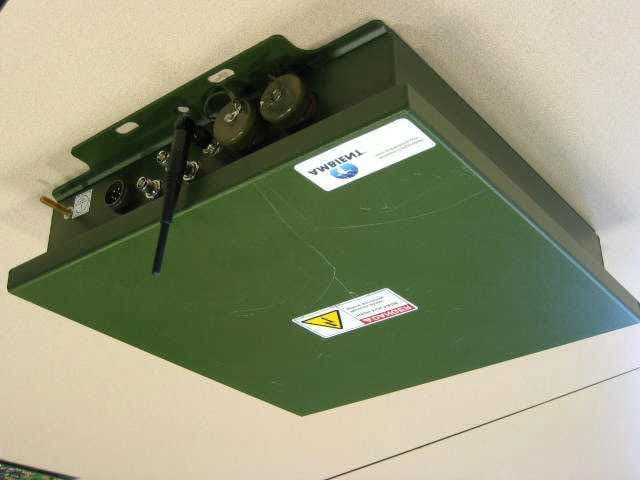
Click to zoom
Application Details
- Equipment Class
- BPL - Access Broadband Over Powerline System
- Date of Grant
- Sep 05, 2006
- Application Purpose
- Original Equipment
- Date of Application
- Jul 13, 2006
- Equipment Note
- X2 PLC NODE
- Frequency Range
- 2.00000000 - 35.00000000
- Company
- Ambient Corporation
- Country
- United States
Documents & Files
Document Text
Text extracted from the exhibit documents filed with the FCC. Open a document above to read the original.
Cover Letter(s)
June 7, 2006 Federal Communication Commission Attention: Application Examiner Reviewing Engineer Re: Request for confidentiality per Section 0.459 of FCC Rules Applicant: Ambient Corporation, Newton, MA 02458 FCC ID: SPKBHPLCAA To whom it may concern, Request is hereby submitted by Ambient Corporation, to withhold from public review certain portions of the application for equipment certification for the referenced FCC identifier. In addition to the previously sent request, to keep the following sections of the application confidential: • Schematics • Detailed Block diagrams • Detailed Operational/Functional Description Ambient requesting that section containing the Internal Photos of the X2 PLC NODE shall be kept confidential also. Rationale for request for confidentiality: Ambient Corporation wishes to keep these items confidential to maintain a competitive advantage in the marketplace. The equipment will be installed by professional installers only and not serviceable in the field. The $145 fee for confidentiality has been submitted along with the fee for certification. If you have questions or need further information, please contact the undersigned. Sincerely, Aron I. Viner Director Compliance & Certification Phone: 617 614 6729 Fax: 617 332 7260 E-mail: [email protected] AMBIENT CORPORATION 79 CHAPEL STREET NEWTON, MA 02458 TELEPHONE (617) 332-0004 FAX: (617) 332-7260
External Photos
FCC ID: SPKBHPLCAA - External Photo
Test Report
Report Number 3098464BOX.001 Page 2 of 19 1.0 Job Description 1.1 Client Information This EUT has been tested at the request of: Company: Ambient Corporation 79 Chapel Street Newton, MA 02458 Contact: Aron Viner Telephone: Fax: Email: (617) 614-6729 (617) 332-7260 [email protected] 1.2 Equipment Under Test Equipment Type: X2 PLC NODE Model Number(s): X200x-x10 Serial number(s): Prototype Manufacturer: Ambient Corporation EUT receive date: 6/5/06 EUT received condition: Engineering Prototype Test start date: 6/5/06 Test end date: 6/29/06 1.3 Test Plan Reference: FCC Part 15, Subpart G 1.4 Test Configuration/Operating Voltage The equipment under test (EUT) was configured with all 3 ports active and wireless module was installed. The EUT was operated at 115 Vac. Testing followed the procedures specified in Appendix C - Guidelines, FCC 04- 245. Special test conditions: i) The EUT was tested at three overhead (mounting on the poles) and three underground locations (mounting on the pad transformer) which areis typical installations. For the overhead testing locations, the distance between poles was at least 300 meters. ii) The EUT was tested in the following four configurations and corresponding output power levels: - On the overhead medium voltage (MV) line with the MV overhead inductive coupler model: 92- 000X - 001. - On the overhead low voltage (LV) line with the LV overhead capacitive coupler model: 62- 000X - XXX. The coupling to the LV line was done differentially. - On the underground MV line with the underground inductive coupler model: C – UGIC -1XX. - On the underground LV line with the underground inductive coupler model: C – UGIC -1XX. Report Number 3098464BOX.001 Page 3 of 19 - The couplers are passive devices and they are part of the system, therefore, separate FCC certification is not required. iii) The EUT was tested in two test modes. Test mode 1 was from 2 to 29.99 MHz and Test mode 2 was from 30-35 MHz, Test mode 1 and Test mode 2 represent the full band of operation. iv) The output power level settings are corrected to be equal for 10, 20 and 30 MHz bands of operation (see output power plot). v) During the test, the EUT was operated in head-end (HE) mode which was defined as the worst case scenario (1000 bursts/second, see burst rate plot). vi) Prior to the field testing, the EUT was pre-scanned in the semi-anechoic chamber to identify the unwanted emissions from 30 MHz to 2 GHz. vii) All overhead testing was performed at horizontal distance of 10 meters from the poles. Slant distances SL were calculated from the formula: SL = [(line height - antenna center height) 2 + (horizontal distance) 2 ] 1/2 The corresponding distance correction factors CF were calculated according to: CF = 40 log 10 (30m/SL) for frequencies below 30 MHz CF = 20 log 10 (10m/SL) for frequencies at and above 30 MHz All underground testing was performed at horizontal distance of 3 meters from the transformers due to the low levels of emissions. The overhead measurements were performed at 10 testing points for test mode 1 and 5 testing points for test mode 2. The underground measurements were performed at 16 testing points around the EUT. All testing were performed with only one coupler connected at any given time. viii) For Test mode 1, active loop antenna which was mounted at 1.2 meter above ground on the non- conductive tripod was used to measure the emissions. The emissions were maximized by rotating the antenna 360°. For Test mode 2, the log periodic antenna which was mounted on the mast was used. The emissions were maximized by raising and lowering the antenna from 1 to 4 meters in both polarizations. ix) During the radiated emissions scans, a 50 KHz sweep was used. Report Number 3098464BOX.001 Page 4 of 19 1.4.1 Block Diagram Block – diagram 1: for testing X2 PLC NODE on the overhead lines Block – diagram 2: for testing X2 PLC NODE on the underground lines Report Number 3098464BOX.001 Page 5 of 19 1.4.2. Cables: Cable Shielding Connector Length (m) Qty. Coaxial cable Coax Metal >3 3 Power cable None Metal >3 1 Ethernet cable Foil Metal >3 1 1.4.3. Support Equipment: None. 1.5 Mode(s) of Operation: The EUT was tested in two test modes. Test mode 1 was from 2 to 30 MHz and Test mode 2 was from 30-35 MHz which was the full band of operation. Power setting was defined by appropriated test mode and configuration. 1.5a EUT Cycle Time: Not applicable. 1.6 Floor Standing Equipment: Applicable:____ Not Applicable:_X_ For floor standing equipment, 40cm RFI field uniformity data is located in the chamber equipment folder. Report Number 3098464BOX.001 Page 6 of 19 2.0 Test Summary TEST STANDARD RESULTS Basic Standards from FCC Part 15 Subpart G SUB-TEST TEST PARAMETER COMMENT Emissions Emissions below specified limits Pass Notes: REVISION SUMMARY – The following changes have been made to this Report: Date Project No. Project Handler Page(s) Item Description of Change Report Number 3098464BOX.001 Page 7 of 19 3.0 Sample Calculations The field strength is calculated by adding the Antenna Factor and Cable Factor, and subtracting the Amplifier Gain (if any) from the measured reading. The basic equation with a sample calculation is as follows: FS = RA + AF + CF – AG - DF Where FS = Field Strength in dBμV/m RA = Receiver Amplitude (including preamplifier) in dBμV CF = Cable Attenuation Factor in dB AF = Antenna Factor in dB AG = Amplifier Gain in dB DF = Distance factor In the following table(s), the reading shown on the data table reflects the preamplifier gain. An example for the calculations in the following table is as follows. Assume a receiver reading of 52.0 dBμV is obtained. The antenna factor of 7.4 dB and cable factor of 1.6 dB is added. The amplifier gain of 29 dB is subtracted, giving a field strength of 32 dBμV/m. This value in dBμV/m was converted to its corresponding level in μV/m. RA = 52.0 dBμV AF = 7.4 dB/m CF = 1.6 dB AG = 29.0 dB FS = 32 dBμV/m DF = 14 dB Level in μV/m = [10( 18 dBμV/…
Text truncated - open the document above for the full version.
Test Setup Photos
FCC ID: SPKBHPLCAA - Overhead Line Setup Photos - 120 Dalmeny Road, Briarcliff Manor, NY Radiated emissions measurement < 30 MHz Radiated emissions measurement > 30 MHz FCC ID: SPKBHPLCAA - Overhead Line Setup Photos - 120 Dalmeny Road, Briarcliff Manor, NY Radiated emissions measurement > 30 MHz Installation of the inductive overhead MV coupler on the MV line FCC ID: SPKBHPLCAA - Overhead Line Setup Photos - 120 Dalmeny Road, Briarcliff Manor, NY Installation of the overhead capacitive coupler on the LV line
Test Setup Photos
FCC ID: SPKBHPLCAA - Overhead Line Setup Photos - 178 Dalmeny Road, Briarcliff Manor, NY Radiated emissions measurements > 30 MHz Radiated emissions measurements < 30 MHz FCC ID: SPKBHPLCAA - Overhead Line Setup Photos - 178 Dalmeny Road, Briarcliff Manor, NY Radiated emission measurements < 30 MHz Installation of the LV capacitive coupler on the LV line FCC ID: SPKBHPLCAA - Overhead Line Setup Photos - 178 Dalmeny Road, Briarcliff Manor, NY Installation of the overhead MV inductive coupler on the MV line
Test Setup Photos
FCC ID: SPKBHPLCAA - Overhead Line Setup Photos - 234 Dalmeny Road, Briarcliff Manor, NY Radiated emissions measurement < 30 MHz Radiated emissions measurement > 30 MHz FCC ID: SPKBHPLCAA - Overhead Line Setup Photos - 234 Dalmeny Road, Briarcliff Manor, NY Radiated emissions measurement; modem location shown on pole Installation of the overhead MV inductive coupler on the MV line and LV capacitive coupler on the LV line
Test Setup Photos
FCC ID: SPKBHPLCAA - Underground Line Setup Photos - Johnston Road, Charlotte, NC (Pad 1) Installation of the inductive underground coupler on MV and LV cables FCC ID: SPKBHPLCAA - Underground Line Setup Photos - Johnston Road, Charlotte, NC (Pad 1) Radiated emissions measurement < 30 MHz Radiated emissions measurement > 30 MHz
Test Setup Photos
FCC ID: SPKBHPLCAA - Underground Line Setup Photos - Cedar Trail, Charlotte, NC (Pad 8) Radiated emissions setup Installation of the inductive underground couplers on the MV and LV cables FCC ID: SPKBHPLCAA - Underground Line Setup Photos - Cedar Trail, Charlotte, NC (Pad 8) Modem connection detail Radiated emissions measurement > 30 MHz FCC ID: SPKBHPLCAA - Underground Line Setup Photos - Cedar Trail, Charlotte, NC (Pad 8) Radiated emissions measurement < 30 MHz
Test Setup Photos
FCC ID: SPKBHPLCAA - Underground Line Setup Photos - Cedar Creek Lane, Charlotte, NC (Pad 11) Radiated emissions measurement < 30 MHz and 10 m Installation of inductive underground couplers on thr MV and LV cables FCC ID: SPKBHPLCAA - Underground Line Setup Photos - Cedar Creek Lane, Charlotte, NC (Pad 11) Installation detail showing modem connections to cable couplers Radiated emissions measurement > 30 MHz and 3m FCC ID: SPKBHPLCAA - Underground Line Setup Photos - Cedar Creek Lane, Charlotte, NC (Pad 11) Radiated emissions measurement < 30 MHz and 3m
Contact Information
Applicant
Aron I Viner(Principal RF engineer)
Technical Contact
Ambient CorporationAron Viner
[email protected]617-614-6729
79 Chapel Street · Newton, Massachusetts · United States
Non-Technical Contact
Ambient CorporationAron Viner
[email protected]617-614-6729
Test Firm
Intertek Testing Services NA Inc.Yaqing Liu
[email protected]978 635 8662
Technical Specifications
| # | Rule Parts | Frequency Range | Power Output |
|---|---|---|---|
| 1 | 15G | 2 MHz - 35 MHz | - |
Other Applications from Ambient Corporation
SPKCOPWRLAA
Feb 15, 2006802.11 a/g Mini-PCI Module
Equipment Class
DTS - Digital Transmission System