SRA-821TRACTOR INTERFACE MODULE
Stemco LLC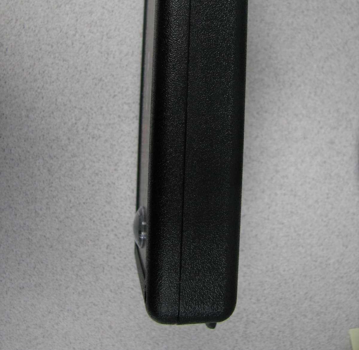
Click to zoom
Application Details
- Equipment Class
- DTS - Digital Transmission System
- Date of Grant
- Sep 21, 2011
- Application Purpose
- Original Equipment
- Date of Application
- Sep 20, 2011
- Equipment Note
- TRACTOR INTERFACE MODULE
- Frequency Range
- 2403.00000000 - 2479.00000000
- Company
- Stemco LLC
- Country
- United States
Documents & Files
Document Text
Text extracted from the exhibit documents filed with the FCC. Open a document above to read the original.
Users Manual
B a t R F T r a c t o r I n t e r f a c e M o d u l e ( T I M ) I n s t a l l a t i o n I n s t r u c t i o n s How It Works The TIM (Tractor Interface Module) is an intuitive device that that interfaces between the PeopleNET on board computer and the BatRF wireless TPM sensors. The TIM ships with the following: 1) A Tractor Interface Module 2) A PeopleNET g3 services interconnect cable 3) Adhesive backed mushroom Velcro and primer to mount the TIM Installing the Unit 1) Locate the PeopleNET g3 Onboard computer (OBC). TIP – Typical mounting locations for the g3 OBC are: a) behind or under the passenger seat b) behind or under the driver’s seat c) For Sleeper Cabs, in the storage area under the bed accessible from the outside of the truck. 2) Select a mounting location for the TIM. IMPORTANT – The TIM wirelessly communicates with the Airbat TPMS sensors; thus the mounting location must meet the following requirements: ● DO mount the TIM at window height or higher in the cab. ● DON’T mount the TIM where metallic objects are within 1” of the front face next to the upper right hand corner of the box (where the receiving antenna is located). ● DON’T mount the TIM within 12 inches of other wireless transmitters (in-cab WiFi, Blu-tooth and microwave ovens). Typically the TIM is mounted above the passenger door (sleeper cabs) or on the lower passenger side of the rear window. TIP – Choose a location that will allow for easy routing for the cable that runs between the TIM and the PeopleNET g3 OBC. 4) Install the TIM Peal the Mushroom head Velcro adhesive back strip and adhere a piece to each end of the back of the TIM. Mount the mating pieces to the TIM and remove the backing adhesive strip. Press the TIM into its mounting location so the adhesive will stick. 4) Install the cable between the TIM and the g3 OBC. Attach the serial port to the 9 pin D connector of the TIM unit and tighten the thumb screws. Connect the cable locking DIN connector to the onboard computer g3 services port (black over-molding) and tighten. Both power and serial communications are run through this cable (eliminates the need for a separate power cable). The TIM connects to the PeopleNet On Board Computer (OBC) via a g3 interface cable. The g3 Services connection is a short cable with a black round locking DIN connector that is provided with the TIM unit. 5) Connect the 9 pin D cable to the TIM and tighten the thumb screws 6) Connect the 6 pin round DIN connector to the BLACK insulated 6 pin DIN connector that comes out of the breakout connector of the PeopleNET OBC and tighten the locking thumb nuts together by hand. NOTE- Don’t connect to the RED or BLUE insulated connectors...it must be the Black insulated Connector which is the g3 services port. NOTE - Both power and serial communications are run through this cable (eliminates the need for a separate power cable). To allow the BatRF TIM to communicate with the PeopleNET g3 services port, the port must be assigned and configured using the PeopleNET in cab keyboard and display. Configuring the PeopleNET g3 Serial Port To allow the BarRF TIM to communicate with the PeopleNET g3 services port, the port must be configured. This is done through the OBC Administration Menu on the display. To configure the port, follow these steps: Step 1: From the main menu select Main and use the down arrow to scroll through the menu options to the bottom of the list. Select “OBC Administration” from the main menu. Step 2: Using the keyboard enter the password, “9238”. Then select “Done”. Step 3: Select “Assign serial port”. Step 4: Select “g3 Services”. This will assign the serial port to be used by g3 Services. Step 5: Select the baud rate. The port can be configured to run at 57,600 baud. If the serial port assignment has been changed, the OBC must be reset to make the change effective. Step 6: Select “OK” to reset the OBC and to finish the port configuration. Testing the Unit After waiting about 30 seconds after the PN display has powered up ...press the UP Arrow until you see a line that says Ok BatRF TPM0 S0 This line is placed on the PN terminal by the BatRF TIM. Every 2.5 seconds the TIM alternates the first character in the line between a space and an “*” or a space and an “!” if there is an error or a low/flat tire. To test the AirBat TIM device after installation turn the power on ................................... Data Entry Into WebBat Record the Vehicle #, Vehicle Type, Sensor Serial # and Wheel Position (optional) and enter the information into WebBat. Trouble Shooting If the TIM is unable to communicate with the PeopleNet OBC it will be indicated with a blink code on the LEDs of the TIM. Part# 09-930-8210 Certifications FCC (USA) This unit complies with Part 15 of the FCC Rules. Operation is subject to the following two conditions: (1) this device may not cause harmful interference, and (2) this device must accept any interference received, including interference that may cause undesired operation. FCC ID: SRA-821 This equipment has been tested and found to comply with the limits for a Class B digital device, pursuant to Part 15 of the FCC Rules. These limits are designed to provide reasonable protection against harmful interference in a residential installation. This equipment generates uses and can radiate radio frequency energy and, if not installed and used in accordance with the instructions, may cause harmful interference to radio communications. However, there is no guarantee that interference will not occur in a particular installation. If this equipment does cause harmful interference to radio or television reception, which can be determined by turning the equipment off and on, the user is encouraged to try to correct the interference by one or more of the following measures: -- Reorient or relocate the receiving antenna. -- Increase the separation between the equipment and receiver. -- Connect the equipment into an outlet on a circuit different from that to which t…
Text truncated - open the document above for the full version.
Cover Letter(s)
July 8, 2011 Timco Engineering, Inc. 849 NW State Road 45 Newberry, FL 32669 888-472-2424 FCC ID: SRA-821 Product Name: 821-7000 Request for Confidentiality Pursuant to Sections 0.457 and 0.459 of the commission’s rules, we hereby request that the following documents be held confidential: • Schematics • Theory of Operation • Block Diagram These materials contain trade secrets and proprietary information and are not customarily released to the public. The public disclosure of this information might be harmful to the company and provide unjustified benefits to our competitors. Dated this 8 Day of July 2011 By: Daniel J. Harding, PE Signature Printed Title: Product Engineer Electrical Design On behalf of : Stemco LP Telephone: 903 239 4176
Cover Letter(s)
July 8, 2011 Timco Engineering 849 N.W. State Road 45 PO Box 370 Newberry, FL 32669 Attn: Director of Certification Authority to Act as Agent FCC On our behalf, I authorize Zarah MacIvor of Nemko USA, Inc., 802 N. Kealy, Lewisville, TX 75057, to act as our agent in the preparation of this application for equipment certification. I certify that submitted documents properly describe the device or system for w hich equipment certification is sought. I also certify that each unit manufactured, imported or marketed, as defined in Federal Communications Commission regulations will have affixed to it a label identical to that submitted for approval with this application. In signing this letter, Applicant certifies that neither the applicant nor any party to the application is not subject to a denial of Federal benefits, that include FCC benefits, pursuant to Section 5301 of the Anti-Drug Abuse Act of 1988, 21 U.S.C. § 862 because of a conviction for possession or distribution of a controlled substance. See 47 CFR 1.2002(b) for the definition of a "party" for these purposes. For instances where our authorized agent signs the application for certification on our behalf, I acknowledge that all responsibility for complying with the terms and conditions for certification, as specified by Timco Engineering still resides with Stemco LP 300 Industrial Blvd. Longview, Tx 75602 Dated this 8 Day of July 20 11 Agency agreement expiration date: 9 Months By: Daniel J. Harding, PE Signature Printed Title: Product Engineer On behalf of : Stemco LP Telephone: (903) 239-4176
ID Label/Location Info
Tractor Interface Label Format and Location FCC ID and IC ID are printed on the top face of the unit using indelible pad printing on the face of the plastic enclosure.
RF Exposure Info
Prediction of MPE limit at a given distance Equation from page 18 of OET Bulletin 65, Edition 97-01 where:S = power density P = power input to the antenna G = power gain of the antenna in the direction of interest relative to an isotropic radiator R = distance to the center of radiation of the antenna Maximum peak output power at antenna input terminal:-2.50(dBm)* Maximum peak output power at antenna input terminal:0.562341325(mW) Antenna gain(maximum):3(dBi)* Maximum antenna gain:1.995262315(numeric) Time Averaging:100(%)* Prediction distance:20(cm)* Prediction frequency:2444(MHz)* MPE limit for uncontrolled exposure at prediction frequency:1.000(mW/cm^2) Power density at prediction frequency:0.000223 (mW/cm^2) This equates to:0.002232185 W/m^2 2 4R PG S
Test Report
Nemko Test Report: 10210985RUS1Rev2 Applicant: Stemco LP 300 Industrial Blvd. Longview, TX 75062 USA Equipment Under Test: Tractor Interface Module (E.U.T.) FCC ID: SRA-821 IC ID: 7413A-821 In Accordance With: FCC Part 15, Subpart C, 15.247 and RSS-210, Issue 8 Digital Transmission Systems Tested By: Nemko USA, Inc. 802 N. Kealy Lewisville, Texas 75057-3136 TESTED BY: DATE: 15 July 2011 David Light, Senior Wireless Engineer APPROVED BY: DATE: 29 August 2011 Tom Tidwell, Reviewer Number of Pages: 23 Nemko USA, Inc. FCC PART 15, SUBPART C & RSS-210 Digital Transmission Systems EQUIPMENT: Tractor Interface Module Test Report No.: 10210985RUS1 Page 2 of 23 Table of Contents SECTION 1. SUMMARY OF TEST RESULTS 3 SECTION 2. EQUIPMENT UNDER TEST (E.U.T.) 5 SECTION 3. OCCUPIED BANDWIDTH 6 SECTION 4. MAXIMUM PEAK OUTPUT POWER 11 SECTION 5. SPURIOUS EMISSIONS 13 SECTION 6. PEAK POWER SPECTRAL DENSITY 17 SECTION 7 - RECEIVER SPURIOUS EMISSIONS 18 SECTION 7. TEST EQUIPMENT LIST 20 ANNEX A - TEST DIAGRAMS 21 Nemko USA, Inc. FCC PART 15, SUBPART C & RSS-210 Digital Transmission Systems EQUIPMENT: Tractor Interface Module Test Report No.: 10210985RUS1 Page 3 of 23 Section 1. Summary of Test Results Manufacturer: Stemco LP Model No.: Tractor Interface Module Serial No.: None General: All measurements are traceable to national standards. These tests were conducted on a sample of the equipment for the purpose of demonstrating compliance with Part 15, Subpart C, Paragraph 15.247 and Industry Canada RSS-210, Issue 8 for Digital Transmission Systems. Radiated tests were conducted is accordance with ANSI C63.4-2003. Radiated emissions are made on an open area test site. A description of the test facility is on file with the FCC and Industry Canada. New Submission Production Unit Class II Permissive Change Pre-Production Unit THIS TEST REPORT RELATES ONLY TO THE ITEM(S) TESTED. THE FOLLOWING DEVIATIONS FROM, ADDITIONS TO, OR EXCLUSIONS FROM THE TEST SPECIFICATIONS HAVE BEEN MADE. See “ Summary of Test Data”. Nemko USA, Inc. authorizes the above named company to reproduce this report provided it is reproduced in its entirety, for use by the company’s employees only. This report must not be used to claim product certification, approval, or endorsement by NVLAP, NIST, or any agency of the Federal Government. Nemko USA, Inc. is a NVLAP accredited laboratory. Any use which a third party makes of this report, or any reliance on or decisions to be made based on it, are the responsibility of such third parties. Nemko USA, Inc. accepts no responsibility for damages, if any, suffered by any third party as a result of decisions made or actions based on this report. This report applies only to the items tested. Nemko USA, Inc. FCC PART 15, SUBPART C & RSS-210 Digital Transmission Systems EQUIPMENT: Tractor Interface Module Test Report No.: 10210985RUS1 Page 4 of 23 Summary Of Test Data NAME OF TEST PARA. NO. RSS PARA. NO. RESULT Powerline Conducted Emissions 15.207(a) RSS-GEN NA Minimum 6 dB Bandwidth 15.247(a)(2) A8.2(a) Complies Maximum Peak Power Output 15.247(b)(3) A8.4(4) Complies Spurious Emissions (Antenna Conducted) 15.247(d) A8.5 Not tested Spurious Emissions (Restricted Bands) 15.247(d)/15.209(a) RSS-GEN Complies Peak Power Spectral Density 15.247(e) A8.2(b) Complies Receiver Spurious Emissions - RSS-GEN Complies Footnotes: 1) The EUT is battery powered. 2) The EUT has an integral antenna. Note: All tests were performed radiated. The conducted power and spectral density was calculated from the EIRP using the manufacturers stated antenna gain of 3 dBi maximum. Nemko USA, Inc. FCC PART 15, SUBPART C & RSS-210 Digital Transmission Systems EQUIPMENT: Tractor Interface Module Test Report No.: 10210985RUS1 Page 5 of 23 Section 2. Equipment Under Test (E.U.T.) General Equipment Information Frequency Band (MHz): 902-928 2400-2483.5 5725-5850 Operating Frequency of Test Sample: 2403 to 2479 MHz 6 dB Bandwidth: 889.8 kHz maximum User Frequency Adjustment: Software controlled Description of EUT 2.4 GHz wireless transceiver. Nemko USA, Inc. FCC PART 15, SUBPART C & RSS-210 Digital Transmission Systems EQUIPMENT: Tractor Interface Module Test Report No.: 10210985RUS1 Page 6 of 23 Section 3. Occupied Bandwidth NAME OF TEST: Occupied Bandwidth PARA. NO.: 15.247(a)(2) TESTED BY: David Light DATE: 11 July 2011 Test Results: Complies. Measurement Data: See 6 dB BW plot Measured 6 dB bandwidth: 889.8 kHz Test Conditions: 49 %RH 22 °C Measurement Uncertainty: +/-1x10 -7 ppm Test Equipment Used: 1767-993-1484-1485 Nemko USA, Inc. FCC PART 15, SUBPART C & RSS-210 Digital Transmission Systems EQUIPMENT: Tractor Interface Module Test Report No.: 10210985RUS1 Page 7 of 23 Test Data – Occupied Bandwidth Low Channel Nemko USA, Inc. FCC PART 15, SUBPART C & RSS-210 Digital Transmission Systems EQUIPMENT: Tractor Interface Module Test Report No.: 10210985RUS1 Page 8 of 23 Test Data – Occupied Bandwidth Mid Channel Nemko USA, Inc. FCC PART 15, SUBPART C & RSS-210 Digital Transmission Systems EQUIPMENT: Tractor Interface Module Test Report No.: 10210985RUS1 Page 9 of 23 Test Data – Occupied Bandwidth High Channel Nemko USA, Inc. FCC PART 15, SUBPART C & RSS-210 Digital Transmission Systems EQUIPMENT: Tractor Interface Module Test Report No.: 10210985RUS1 Page 10 of 23 Test Data – Occupied Bandwidth 99% Bandwidth (Industry Canada) Nemko USA, Inc. FCC PART 15, SUBPART C & RSS-210 Digital Transmission Systems EQUIPMENT: Tractor Interface Module Test Report No.: 10210985RUS1 Page 11 of 23 Section 4. Maximum Peak Output Power NAME OF TEST: Maximum Peak Output power PARA. NO.: 15.247(b)(3) TESTED BY: David Light DATE: 11 July 2011 Test Results: Complies. Measurement Data: Freq EIRP Gain Output Power Output Power (MHz) (dBm) (dBi) (dBm) (mW) 2403 8.0 3 5.0 3.14 2441 6.9 3 3.9 2.44 2479 6.7 3 3.7 2.33 Frequency (MHz) Measured Level (dBuV/m) AF (dB/m) Preamp Gain (dB) Ca ble Loss (dB) Corrected Level (dBuV/m@3m) Corrected Level (uV/m) EIRP (W) EIRP (mW…
Text truncated - open the document above for the full version.
Contact Information
Applicant
Mark Kranz
Test Firm
Nemko Dallas, Inc.Mike Cantwell
Technical Specifications
| # | Rule Parts | Frequency Range | Power Output |
|---|---|---|---|
| 1 | 15C | 2.40 GHz - 2.48 GHz | 3.00 mW |
Other Applications from Stemco LLC

SRA-830
Sep 16, 2012Aeris Tire Inflation System
Equipment Class
DTS - Digital Transmission System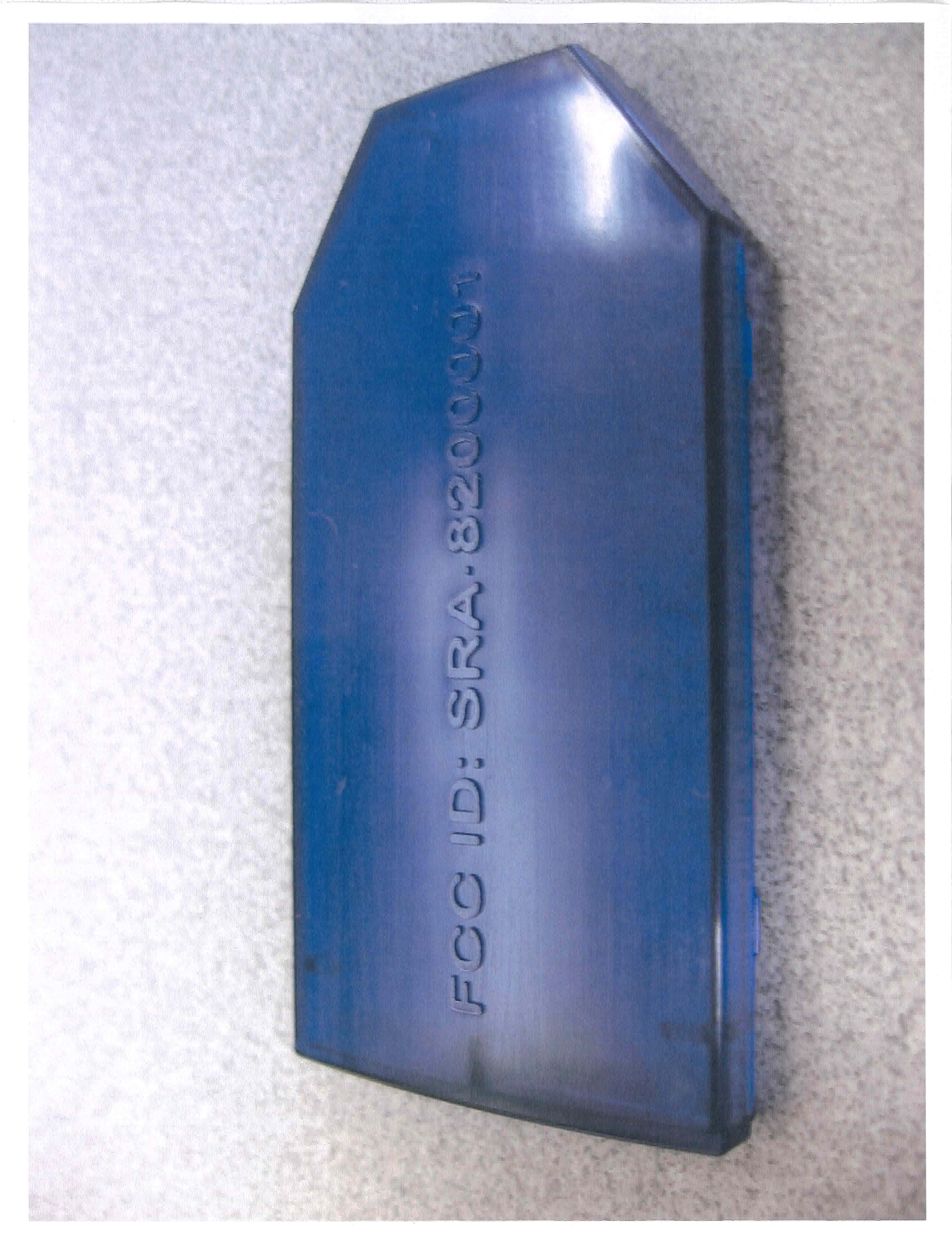
SRA-8200001
Oct 25, 2007DIGITAL TRANSMISSION SYSTEM
Equipment Class
DTS - Digital Transmission System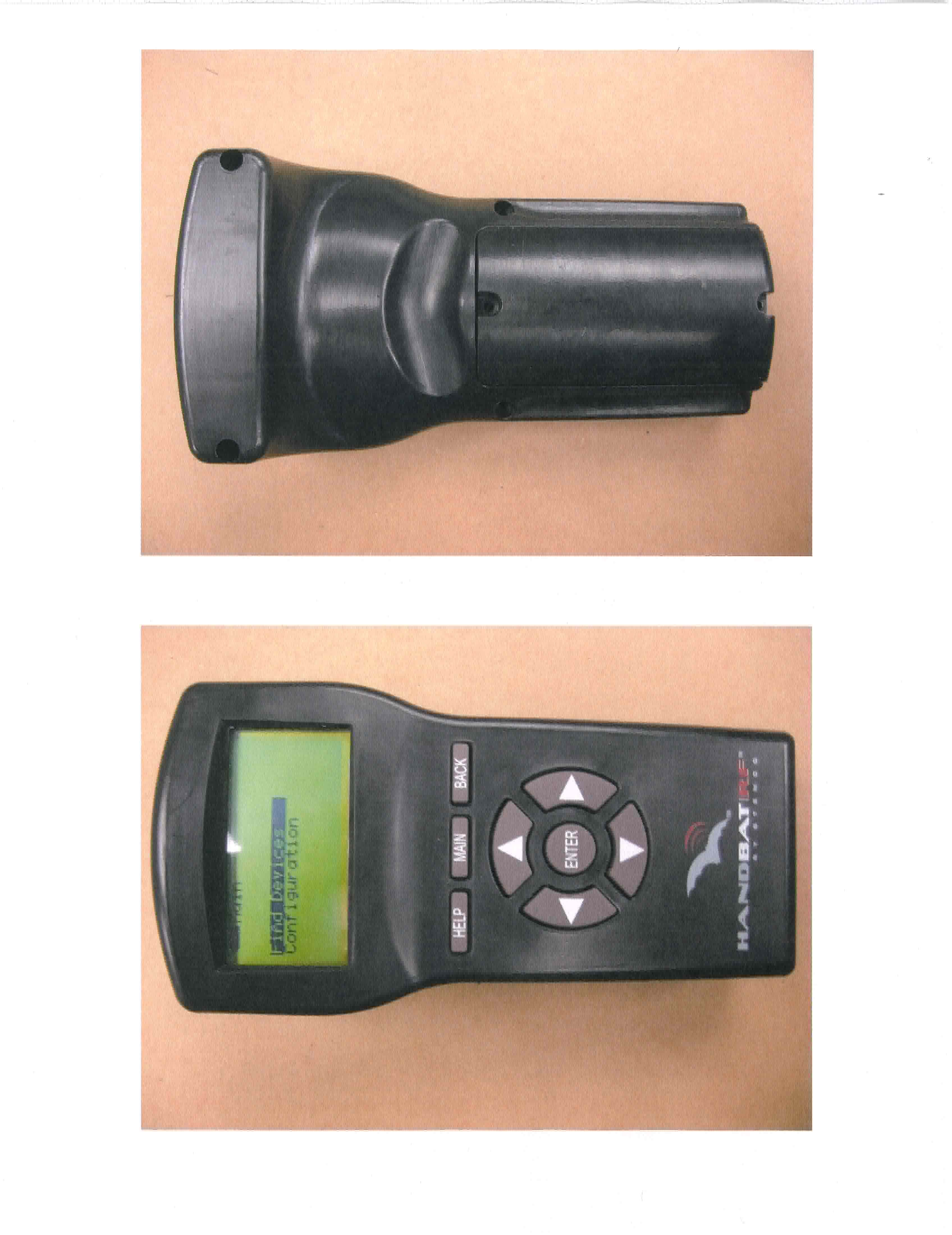
SRA-8200000
Jun 14, 2007RFID Reader
Equipment Class
DTS - Digital Transmission System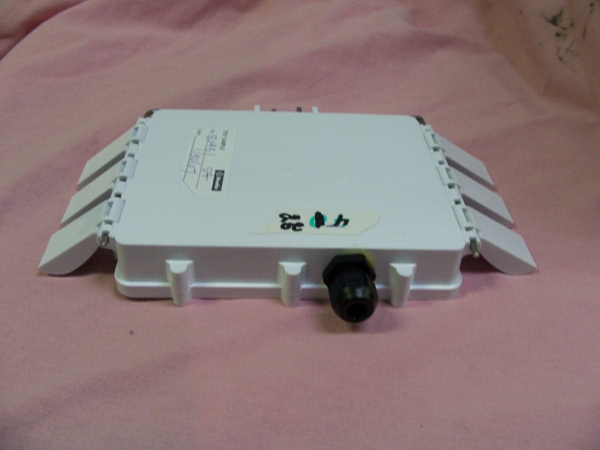
SRA-8400000
Mar 25, 2007Transceiver Module
Equipment Class
DTS - Digital Transmission System
SRA-816
Mar 08, 2007Digital Transmission System
Equipment Class
DTS - Digital Transmission System