SRA-830Aeris Tire Inflation System
Stemco LLC
Click to zoom
Application Details
- Equipment Class
- DTS - Digital Transmission System
- Date of Grant
- Sep 16, 2012
- Application Purpose
- Original Equipment
- Date of Application
- Sep 13, 2012
- Equipment Note
- Aeris Tire Inflation System
- Frequency Range
- 2404.25000000 - 2480.25000000
- Company
- Stemco LLC
- Country
- United States
Documents & Files
Document Text
Text extracted from the exhibit documents filed with the FCC. Open a document above to read the original.
Users Manual
Aeris Installation, Service and Troubleshooting Manual Page | 1 STEMCO Aeris Installation Manual Date: 5/29/2012 Rev: A • Aeris TM by STEMCO, an advanced automatic tire inflation system based on patented rotary sealing technology and precision electronic airflow detection. The system is designed to keep commercial trailer tires properly inflated using air pressure from the trailer’s braking system. • The rotary seal employed in Aeris TM by STEMCO differs dramatically from currently available systems and is targeted to increase the reliability and durability of these components substantially. The rotary seal in an automatic tire inflation system is a critical component – it prevents the higher pressures needed to inflate commercial tires (typically 100 psi) from leaking into the wheel end, which can handle no more than 6 psi. Excess pressure can cause the wheel end seal to fail prematurely, causing lubricants to exit the hub and leaving moving parts susceptible to wear and seizure – a dangerous scenario. In addition to the high reliability and durability of the patented sealing system, Aeris TM by STEMCO also includes several one-way pressure relief valves per axle to ensure that the wheel-end is never pressurized. • Aeris TM by STEMCO also includes a very sensitive electronic flow detection technology capable of informing the driver whether the system is making a minor adjustment to tire pressure or if a major leak is present. A “Smart Sense” wheel end identification option will inform the driver which wheel end is taking air – saving time and labor in the search and repair of tire leaks. • Aeris TM by STEMCO represents a leap forward in automatic tire inflation technology. STEMCO starts with an unwavering commitment to increase the safety of our roadways by protecting the wheel end from damaging air pressure, and then added several additional safeguards and features. Aeris augments our BatRF tire pressure monitoring systems to complete our suite of tire pressure management solutions. Aeris Installation, Service and Troubleshooting Manual Page | 2 General View of Aeris Components Installed. Refer to this installation guide on how to install the Aeris system on trailers. Aeris Installation, Service and Troubleshooting Manual Page | 3 Table of Contents General Information........................................................................................5 About this Manual...................................................................................5 Explanation of Signal Words.....................................................................5 Important Safety Notices..........................................................................5 General Service Information.....................................................................6 General Service Installation Note...............................................................6 Contact STEMCO.....................................................................................7 Literature Link..............................................................................7 Phone........................................................................................7 System Overview...........................................................................................7 Aeris Overview......................................................................................7 System Features....................................................................................7 Aeris Specifications................................................................................8 System Operation..................................................................................8 How System Works.....................................................................8 System Components..............................................................................9 Recommended Tool List..........................................................................9 Aeris Installation................................................................................................................9 Trailer Preparation.................................................................................9 Axle Preparation....................................................................................10 Drain Oil.....................................................................................10 Remove Welsh Plug.....................................................................11 Drill Fixture (How to Make) and Use................................................12 Drill & Tap Holes in Axle...............................................................12 Clocking Wheels...................................................................................16 Axle Hose Installation............................................................................18 Split Loom Tubing Protection Installation...................................................18 Center Vent Line Installation...................................................................19 Axle Plug Installation.............................................................................20 Aeris Hubcap Assembly Installation..........................................................21 Control Box Installation...........................................................................24 Connecting Airlines to Control Box............................................................26 Air Lines to Compressed Air Tank...................................................29 Tire Hose Installation..............................................................................31 Light Kit and Wiring Installation................................................................32 Decal Location.....................................................................................39 Aeris Installation, Service and Troubleshooting Manual Page | 4 System Installation Check...............................................…
Text truncated - open the document above for the full version.
Cover Letter(s)
Federal Communications Commission 7435 Oakland Mills Road Columbia, MD 21046 USA Authority to Act as Agent to the Federal Communications Commission On our behalf, I appoint Nemko USA, Inc. to act as agent in the preparation of this application for equipment authorization to the Federal Communications Commission. I certify that submitted Exhibits properly describe the device or system for which equipment authorization is sought. I also certify that each unit manufactured, imported or marketed, as defined in the Commission's regulations will have affixed to it a label identical to that submitted for approval with this application. APPLICANT ANTI-DRUG ABUSE CERTIFICATION: In signing this letter, Applicant certifies that, in the case of an individual applicant, he or she is not subject to a denial of federal benefits, that includes FCC benefits, pursuant to Section 5301 of the Anti-Drug Abuse Act of 1988, 21 U.S.C. 853(a), or, in the case of a non-individual applicant (e.g. corporation, partnership or other unincorporated association), no party to the application is subject to a denial of federal benefits, that includes FCC benefits, pursuant to that section. For the definition of a "party" for these purposes, see 47 CFR 1.2002(b). Dated this 26 Day of June,2012 Agency agreement expiration date: 6 months after above stated start date Company:Stemco LP By: Mark Kranz Title: Sr Product Engineer Electrical Design Telephone: 903 758 9981 Applicant:
Cover Letter(s)
Equipment Autorization Division Federal Communications Commission 7435 Oakland Mills Road Columbia, MD 21046 FCC ID: SRA-830 Product Name: SRA-830 Request for Confidentiality Pursuant to Sections 0.457 and 0.459 of the commissions rules, we hereby request that the following documents be held confidential: • Schematics • Theory of Operation • Parts list Block Diagram These materials contain trade secrets and proprietary information and are not customarily released to the public. The public disclosure of this information might be harmful to the company and provide unjustified benefits to our competitors. Dated this 26 Day of June 20 12 By: Mark Kranz Signature Printed Title: Sr Product Engineer Electrical Design On behalf of : Stemco LP Telephone: 903 758 9981
ID Label/Location Info
This is the label affixed to the device. The rest of the regulatory requirements will be listed at the end of the manual (installation instructions) FCC ID: SRA-830 and Canadian number IC: 7413A-830 See picture below Actual size of label is first picture. .
RF Exposure Info
Prediction of MPE limit at a given distance Equation from page 18 of OET Bulletin 65, Edition 97-01 where:S = power density P = power input to the antenna G = power gain of the antenna in the direction of interest relative to an isotropic radiator R = distance to the center of radiation of the antenna Maximum peak output power at antenna input terminal:-6.6(dBm)* Maximum peak output power at antenna input terminal:0.2(mW) Antenna gain(maximum):3(dBi)* Maximum antenna gain:2.00(numeric) Time Averaging:100(%)* Prediction distance:20(cm)* Prediction frequency:2480.25(MHz)* MPE limit for uncontrolled exposure at prediction frequency:1.000(mW/cm^2) Power density at prediction frequency:0.00009 (mW/cm^2) This equates to:0.0009 W/m^2 2 4R PG S
Test Report
Nemko Test Report: 10227668RUS1rev1 Applicant: Stemco LP 300 Industrial Blvd. Longview, TX 75062 USA Equipment Under Test: 830 (E.U.T.) FCC ID.: SRA-830 IC: 7413A-830 In Accordance With: FCC Part 15, Subpart C, 15.247 and Industry Canada RSS-210, Issue 8 Digital Transmission Systems Tested By: Nemko USA, Inc. 802 N. Kealy Lewisville, Texas 75057-3136 TESTED BY: DATE: 21 August 2012 David Light, Senior Wireless Engineer APPROVED BY: DATE: 21 August 2012 Mike Cantwell Number of Pages: 29 Nemko USA, Inc. FCC PART 15, SUBPART C & Industry Canada RSS-210, Issue 8 Digital Transmission Systems EQUIPMENT: SRA-830 Test Report No.:10227668RUS1rev1 Page 2 of 29 Table of Contents SECTION 1. SUMMARY OF TEST RESULTS 3 SECTION 2. EQUIPMENT UNDER TEST (E.U.T.) 5 SECTION 3. OCCUPIED BANDWIDTH 6 SECTION 4. MAXIMUM PEAK OUTPUT POWER 11 SECTION 5 SPURIOUS EMISSIONS AT ANTENNA TERMINALS 13 SECTION 6. RADIATED EMISSIONS 15 SECTION 7. PEAK POWER SPECTRAL DENSITY 17 SECTION 8. TEST EQUIPMENT LIST 18 ANNEX A - TEST DETAILS 19 ANNEX B - TEST DIAGRAMS 27 Nemko USA, Inc. FCC PART 15, SUBPART C & Industry Canada RSS-210, Issue 8 Digital Transmission Systems EQUIPMENT: SRA-830 Test Report No.:10227668RUS1rev1 Page 3 of 29 Section 1. Summary of Test Results Manufacturer: Stemco LP Model No.: 830 Serial No.: None General: All measurements are traceable to national standards. These tests were conducted on a sample of the equipment for the purpose of demonstrating compliance with Part 15, Subpart C, Paragraph 15.247 and Industry Canada RSS-210, Issue 8 for Digital Transmission Systems. Radiated tests were conducted is accordance with ANSI C63.4-2003. Conducted tests were made in accordance with FCC OET Bulletin 558074 D01 v01. Radiated emissions are made on an open area test site. A description of the test facility is on file with the FCC and Industry Canada. New Submission Production Unit Class II Permissive Change Pre-Production Unit THIS TEST REPORT RELATES ONLY TO THE ITEM(S) TESTED. THE FOLLOWING DEVIATIONS FROM, ADDITIONS TO, OR EXCLUSIONS FROM THE TEST SPECIFICATIONS HAVE BEEN MADE. See “ Summary of Test Data”. This report must not be used to claim product certification, approval, or endorsement by NVLAP, NIST, or any agency of the Federal Government. Nemko USA, Inc. is a NVLAP accredited laboratory. Nemko USA, Inc. authorizes the above named company to reproduce this report provided it is reproduced in its entirety, for use by the company’s employees only. This report must not be used to claim product certification, approval, or endorsement by NVLAP, NIST, or any agency of the Federal Government. Nemko USA, Inc. is a NVLAP accredited laboratory. Any use which a third party makes of this report, or any reliance on or decisions to be made based on it, are the responsibility of such third parties. Nemko USA, Inc. accepts no responsibility for damages, if any, suffered by any third party as a result of decisions made or actions based on this report. This report applies only to the items tested. Nemko USA, Inc. FCC PART 15, SUBPART C & Industry Canada RSS-210, Issue 8 Digital Transmission Systems EQUIPMENT: SRA-830 Test Report No.:10227668RUS1rev1 Page 4 of 29 Summary Of Test Data NAME OF TEST PARA. NO. RESULT Powerline Conducted Emissions 15.207(a) / RSS-Gen 7.2.4 NA Minimum 6 dB Bandwidth 15.247(a)(2) / RSS-210 A8.2(a) Complies Maximum Peak Power Output 15.247(b)(3) / RSS-210 A8.4(4) Complies Spurious Emissions (Antenna Conducted) 15.247(d) / RSS-210 A8.5 Complies Spurious Emissions (Restricted Bands) 15.247(d)/15.209(a) / RSS-Gen 7.2.2 Complies Peak Power Spectral Density 15.247(e) / RSS-210 A8.2(b) Complies Footnotes: The EUT is battery powered. Revisions: Revision1 Recalculated EIRP using field strength method. Nemko USA, Inc. FCC PART 15, SUBPART C & Industry Canada RSS-210, Issue 8 Digital Transmission Systems EQUIPMENT: SRA-830 Test Report No.:10227668RUS1rev1 Page 5 of 29 Section 2. Equipment Under Test (E.U.T.) General Equipment Information Frequency Band (MHz): 902-928 2400-2483.5 5725-5850 Operating Frequency of Test Sample: 2404.25 to 2480.25 MHz User Frequency Adjustment: Factory set Input Power: 12 Vdc automotive battery. Description of EUT Wireless air flow monitor for automotive use. Nemko USA, Inc. FCC PART 15, SUBPART C & Industry Canada RSS-210, Issue 8 Digital Transmission Systems EQUIPMENT: SRA-830 Test Report No.:10227668RUS1rev1 Page 6 of 29 Section 3. Occupied Bandwidth NAME OF TEST: Occupied Bandwidth PARA. NO.: 15.247(a)(2) RSS-210 A8.2(a) TESTED BY: David Light DATE: 13 July 2012 Test Results: Complies. Measurement Data: See attached plots Test Conditions: 54 %RH 22 °C Measurement Uncertainty: +/-1x10 -7 ppm Test Equipment Used: 1036-1783-1480-1016 Nemko USA, Inc. FCC PART 15, SUBPART C & Industry Canada RSS-210, Issue 8 Digital Transmission Systems EQUIPMENT: SRA-830 Test Report No.:10227668RUS1rev1 Page 7 of 29 Test Data – Occupied Bandwidth Low Channel Nemko USA, Inc. FCC PART 15, SUBPART C & Industry Canada RSS-210, Issue 8 Digital Transmission Systems EQUIPMENT: SRA-830 Test Report No.:10227668RUS1rev1 Page 8 of 29 Test Data – Occupied Bandwidth Mid Channel Nemko USA, Inc. FCC PART 15, SUBPART C & Industry Canada RSS-210, Issue 8 Digital Transmission Systems EQUIPMENT: SRA-830 Test Report No.:10227668RUS1rev1 Page 9 of 29 Test Data – Occupied Bandwidth 20 dB BW for IC Nemko USA, Inc. FCC PART 15, SUBPART C & Industry Canada RSS-210, Issue 8 Digital Transmission Systems EQUIPMENT: SRA-830 Test Report No.:10227668RUS1rev1 Page 10 of 29 Test Data – Occupied Bandwidth Upper Channel Nemko USA, Inc. FCC PART 15, SUBPART C & Industry Canada RSS-210, Issue 8 Digital Transmission Systems EQUIPMENT: SRA-830 Test Report No.:10227668RUS1rev1 Page 11 of 29 Section 4. Maximum Peak Output Power NAME OF TEST: Maximum Peak Output power PARA. NO.: 15.247(b)(3) RSS-210 A8.4(4) TESTED BY: David Light DATE: 13 July 2012 Test Results: Complies. Measurement Data: Refer to attached data Test Conditions: 54 %R…
Text truncated - open the document above for the full version.
Contact Information
Applicant
Mark Kranz
Non-Technical Contact
Nemko USA, Inc.Zarah G MacIvor
[email protected]214-629-5683
Test Firm
Nemko Dallas, Inc.Mike Cantwell
Technical Specifications
| # | Rule Parts | Frequency Range | Power Output |
|---|---|---|---|
| 1 | 15C | 2.40 GHz - 2.48 GHz | 200.00 µW |
Other Applications from Stemco LLC
SRA-821
Sep 21, 2011TRACTOR INTERFACE MODULE
Equipment Class
DTS - Digital Transmission System
SRA-8200001
Oct 25, 2007DIGITAL TRANSMISSION SYSTEM
Equipment Class
DTS - Digital Transmission System
SRA-8200000
Jun 14, 2007RFID Reader
Equipment Class
DTS - Digital Transmission System
SRA-8400000
Mar 25, 2007Transceiver Module
Equipment Class
DTS - Digital Transmission System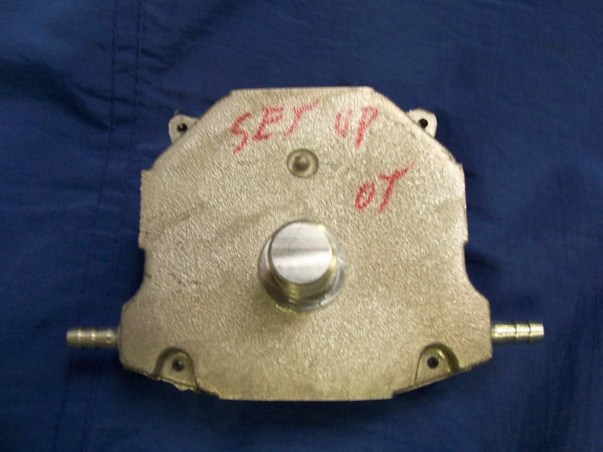
SRA-816
Mar 08, 2007Digital Transmission System
Equipment Class
DTS - Digital Transmission System