SU6-RCSFR1Remote Control Receiver for Crane
Tadano Ltd.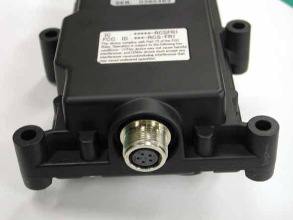
Click to zoom
Application Details
- Equipment Class
- CYY - Communications Receiver used w/Pt 15 Transmitter
- Date of Grant
- Feb 07, 2005
- Application Purpose
- Original Equipment
- Date of Application
- Feb 07, 2005
- Equipment Note
- Remote Control Receiver for Crane
- Frequency Range
- 429.25000000 - 429.73750000
- Company
- Tadano Ltd.
- Country
- Japan
Documents & Files
Document Text
Text extracted from the exhibit documents filed with the FCC. Open a document above to read the original.
Users Manual
2004 PRINTED IN JAPAN 0412 E O307-39(U)-1E Radio-control System ( RCS-FT1 ) for Boom Truck Series CAUTION: Read this manual before operating. Save this manual for future reference. M037910E Safety Caution A-1 Safety Caution Safety Caution FCC NOTICE This device complies with Part 15 of the FCC Rules.Operation is subject to the following two conditions: (1) This device may not cause harmful interference, and (2) This device must accept any interference received, including interference that may cause undesired operation. (1) Do not remove the certificate label. The purpose of the certificate label on the radio-control system is to certify that the device conforms to the Radio Law. Using a system without the certificate label is illegal. Do not remove the certificate label. (2) Dismantling/modification is prohibited. Do not dismantle or modify the radio-control system. Dismantling or modifying the radio-control system is illegal and punishable. Request a repair at the nearest TADANO distributor or dealer if the radio-control system has a problem. Incorrect operation and inspection/maintenance of the crane is very dangerous, causing bodily accidents such as death or serious injury. Before using the crane, carefull y read the operation and maintenance manual of the crane and this manual so that you fully understand them. Never operate and inspect/maintain the crane until you fully understand the manuals. M22318 Communication unitTransmitter IC :-RCSFR1 FCC ID:-RCS-FR1 IC :-RCSFT1 FCC ID:-RCS-FT1 M22649E Warning M037910E Safety Caution A-2 Safety Caution (3) Always keep the transmitter clean. When the transmitter gets dusty or dirty, wipe the dust or dirt away with a dry soft cloth. The attached dust or dirt may give unfavorable impact on operations of the motion selection switches or speed control lever, causing operation failures or malfunctions of the crane. (4) Handle the transmitter with care. Do not throw or drop the transmitter, as a strong shock may cause damage or failure. When you carry the transmitter with you, do not drop it. Hang the transmitter onto a portable hook or use an extended strap to hang the transmitter from your neck. (5) Store the transmitter in a safe place. Store the radio-control transmitter in a safe place after replacing it back into the transmitter-storing bag. Do not leave or store it in a place exposed to sunlight or rain or a place with a high temperature or high humidity. M22310 M22321 M22319E M22650E M037910E Safety Caution A-3 Safety Caution (6) Remove the batteries of the radio-control transmitter when not in use for a long time. Remove the batteries of the transmitter when the transmitter is not used for a long time, as the batteries may leak if not removed. (7) High pressure cleaning is prohibited. Electric devices, such as control unit and communication unit, may develop trouble if water enters inside them. Please do not clean the electric devices with high pressure. (8) Pay attention to surrounding conditions. It is dangerous if your attention is paid only to lifted cargos. Also pay full attention to the conditions of the main unit of the crane. Especially, be careful with a vehicle turnover. (9) Keep the lifted cargo weight lower than the rated lifting capacity for empty chassis. Be careful with overloading to prevent accidents. M22313E Dry battery Battery cover M22655 M22651 M037910E Safety Caution A-4 Safety Caution (10) Be careful with radio wave conditions. Since the radio-control system uses radio waves, it cannot avoid influences of electromagnetic interference, radio interference and exogenous noise. Such influences may hinder the radio wave transmission, stopping the crane operation. Stopping of the crane during the operation may cause dangers. It is especially dangerous during a swing operation of the crane. Pay attention to the following when operating the radio-control system. It is dangerous to operate the crane under conditions with low radio wave transmission, especially during a swing operation of the crane since the crane intermittently moves. Before starting the operation, confirm that there is no problem in the crane operation under no load condition. Too large a distance between the transmitter and communication unit may not only hinder the radio wave transmission but also increase influences of noise. Normally, operate within the operating radius of the crane. Obstacles such as wire nettings and metal doors between the transmitter and communication unit may hinder the radio wave transmission. Use manual control operation under unfavorable radio transmission conditions. Noise from a vehicle’s air-conditioner used during the operation may cause an intermittent crane operation. Refrain from using an air-conditioner when its noise influences the radio-control operation. Noise from an approaching motorcycle to the operation site may cause an intermittent crane operation. Confirm that there is no motorcycle approaching during the operation. M22652E (Wire netting) ? M22653 ?
Users Manual
M037920E Contents 1 Contents Contents Safety Caution A-1 Preface 2 Configurations of Radio-control System 3 Names and Functions of Each Section 4 1. Radio-control Block 4 2. Crane 7 Safety Functions of Radio-control System 8 1. Auto Power-off Function 8 2. Switch Failure Detection Function 8 3. Continual Operation Restriction Function 9 4. Instant Stop Alarm Function 9 5. Alarm Function 10 Radio-control 11 1. Preparation for Radio-control Operation 11 2. How to Operate the Radio-control 13 3. Changing Speed Mode 15 4. Engine Start-up Operation 16 5. Emergency Stop Operation 16 Manual Operation 17 Battery Replacement for Transmitter 18 1. Battery Replacement Timing 18 2. How to Replace Batteries 18 Measures for Emergency Case 19 1. When Radio-Control Operation is Impossible 19 2. If the Radio-control is not Possible 22 Troubleshooting Guide 23 Daily Inspection 25 M037930E Preface 2 Preface Preface This operation and maintenance manual is for safe and proper operation and inspection/maintenance of the radio-control system whose model is shown in the following table. Refer to the operation and maintenance manual of the main unit of the crane for operation and inspection/maintenance of the main unit. Applicable model Transmitter RCS-FT1 Communication unit RCS-FR1 Radio-control system Control unit RCS-FC1 Confirm the model of your radio-control system with the nameplates shown in the following illustrations. Illustrations in this manual may differ from the actual products in details. Note that the illustrations for explanation purposes are sometimes drawn without any cover or guard. Note that the products may be subject to modifications that are not reflected in this manual, because of product improvement. When transferring the crane to another party, transfer this manual also together with the crane. Should you have any comments or inquiries on the delivered crane or this manual, contact the nearest TADANO distributor or dealer. Transmitter Communication unit Control unit M22654E M037940E Configurations of Radio-control System 3 Configurations of Radio-control System Configurations of Radio-control System M22656E Control unit Communication unit Speaker (for alarm) Emergency stop lamp Radio control valve Transmitter Portable hook Transmitter storing bag M037950E Names and Functions of Each Part 4 Names and Functions of Each Part Names and Functions of Each Part 1. Radio-control Block 4 Power switch 5 Speed mode switch 3 Power LED (Red) 13 Emergency stop LED (Red) 11 Engine start switch 10 Horn switch 12 Emergency stop switch 1 Engine start LED (Red/Green)2 Speed mode LED (Red/Green) 6 Elevation selection switch 9 Swing selection switch 7 Hook selection switch 8 Extension selection switch 16 Speed control lever 18 Connector for remote-control operation 19 Reception lamp 17 Mode indicator lamp 15 Battery cover Transmitter Communication Unit Control Unit 14 Strap M22657E 20 Communication unit LED (Red/Green) 0200E S 2 R C S -F R 1 I C : - R C S F R 1 F C C I D : -R C S - F R 1 Motion selection switches 69 M037950E Names and Functions of Each Part 5 Names and Functions of Each Part 1. Engine Start LED The LED shows the condition of the engine start switch. When the switch is not operated: Turned off When the switch is operated: Turned on (Red) 2. Speed Mode LED The LED shows the speed modes. At high-speed mode: Turned off At medium-speed mode: Turned on (Green) At low-speed mode: Turned on (Red) 3. Power LED The LED shows the power ON/OFF of the transmitter and battery consumption condition. At power OFF: Turned off At power ON: Turned on (Red) At battery exhaustion: Flashing (Red) 4. Power Switch This is the switch for power ON/OFF of the transmitter. When the power switch is pressed while the radio-control /manual changeover switch of the crane is turned to “Radio” position after PTO is set to “Engaged” state, the power of the transmitter is turned on and the power LED lights up. When the power switch is pressed once again, the power is turned off and the power LED turns off. 5. Speed Mode Switch This is the switch to select the speed mode. Every time the switch is pressed, the mode changes in the order of: “low-speed” → “medium-speed” → “high-speed” →“low-speed” •••••. At the same time, the speed mode LED changes in the order of: “turned on in red” → “turned on in green” → “turned off” → “turned on in red” •••••. 6. Elevation Selection Switch 7. Hook Selection Switch 8. Extension Selection Switch 9. Swing Selection Switch These are the motion selection switches for the crane operation. When the speed control lever is pulled after the motion selection switch is changed, the crane can be operated. 10. Horn Switch When the switch is pressed, the vehicle’s horn sounds. 11. Engine Start Switch This is the switch to output the engine start signal. When the switch is pressed, the engine starts up. The engine start-up is disabled under the emergency stop state. 12. Emergency Stop Switch Pressing the switch causes an emergency stop and all the crane operation stops. At the same time, the emergency stop LED and emergency stop lamp of the crane light up. When the switch is pressed once again, the emergency stop state is released, and the emergency stop LED and emergency stop lamp of the crane turn off. 13. Emergency Stop LED The LED shows the emergency stop state. Under normal condition: Turned off Under emergency stop state: Turned on (Red) 14. Strap The strap is for portable use of the transmitter. Hook the transmitter onto a belt on your waist or hang it from your neck by extending the strap. 15. Battery Cover This is used when replacing the batteries. 16. Speed Control Lever This is the lever to adjust operation speeds of the crane. According to the pulling amount of the lever, the engine speed increases to increase the speed of the crane. M037950E Names and Functions of Each Part 6 Names and Functions of Each Part 17. Mode Indicator Lamp The lamp indicates the current operation mode. At power on o…
Text truncated - open the document above for the full version.
External Photos
External Photo 1 Receiver Model RCSFR1 External Photo 2 Receiver Model RCSFR1
Internal Photos
Internal Photo 1 Receiver Model RCSFR1 External Photo 2 Receiver Model RCSFR1
Test Setup Photos
Setup Photo Receiver Model RCSFR1
Contact Information
Applicant
Yoichiro Nishi(General Manager)
Test Firm
Tokin EMC Engineering Co., Ltd.Shida Hiro
Technical Specifications
| # | Rule Parts | Frequency Range | Power Output |
|---|---|---|---|
| 1 | 15B | 429.25 MHz - 429.7375 MHz | - |
Other Applications from Tadano Ltd.
SU6-RCSFT1-433
Mar 25, 2014Remote Control Transmitter
Equipment Class
DSC - Part 15 Security/Remote Control Transmitter
SU6-RCSFT1
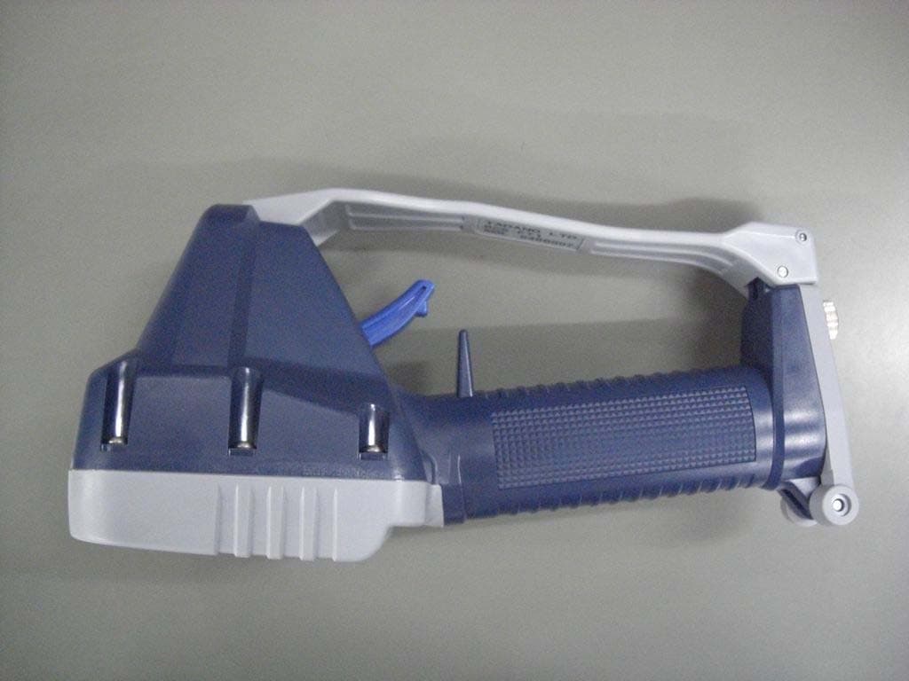
Feb 07, 2005Remote Control Transmitter for Crane
Equipment Class
DSC - Part 15 Security/Remote Control Transmitter