SU6-RCSFT1-433Remote Control Transmitter
Tadano Ltd.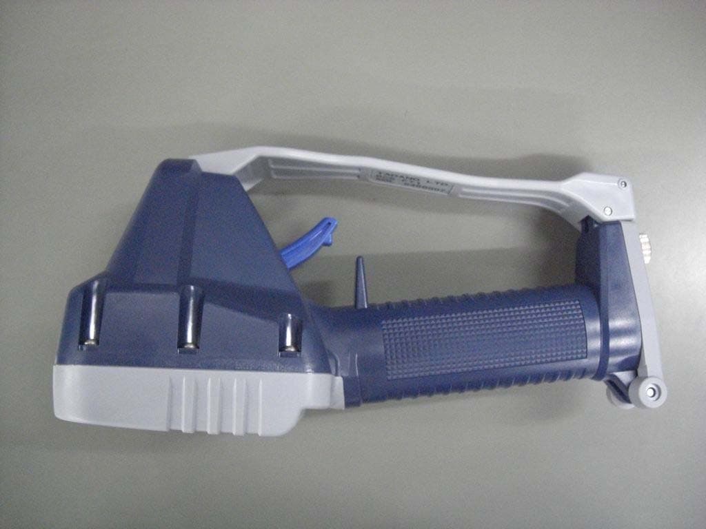
Click to zoom
Application Details
- Equipment Class
- DSC - Part 15 Security/Remote Control Transmitter
- Date of Grant
- Mar 25, 2014
- Application Purpose
- Original Equipment
- Date of Application
- Mar 25, 2014
- Equipment Note
- Remote Control Transmitter
- Frequency Range
- 433.30000000 - 433.78750000
- Company
- Tadano Ltd.
- Country
- Japan
Documents & Files
Document Text
Text extracted from the exhibit documents filed with the FCC. Open a document above to read the original.
Users Manual
2004 PRINTED IN JAPAN 0412 E O307-39(U)-1E Radio-control System ( RCS-FT1 ) for Boom Truck Series CAUTION: Read this manual before operating. Save this manual for future reference. M037920E Contents 1 Contents Contents Safety Caution A-1 Preface 2 Configurations of Radio-control System 3 Names and Functions of Each Section 4 1. Radio-control Block 4 2. Crane 7 Safety Functions of Radio-control System 8 1. Auto Power-off Function 8 2. Switch Failure Detection Function 8 3. Continual Operation Restriction Function 9 4. Instant Stop Alarm Function 9 5. Alarm Function 10 Radio-control 11 1. Preparation for Radio-control Operation 11 2. How to Operate the Radio-control 13 3. Changing Speed Mode 15 4. Engine Start-up Operation 16 5. Emergency Stop Operation 16 Manual Operation 17 Battery Replacement for Transmitter 18 1. Battery Replacement Timing 18 2. How to Replace Batteries 18 Measures for Emergency Case 19 1. When Radio-Control Operation is Impossible 19 2. If the Radio-control is not Possible 22 Troubleshooting Guide 23 Daily Inspection 25 M037930E Preface 2 Preface Preface This operation and maintenance manual is for safe and proper operation and inspection/maintenance of the radio-control system whose model is shown in the following table. Refer to the operation and maintenance manual of the main unit of the crane for operation and inspection/maintenance of the main unit. Applicable model Transmitter RCS-FT1 Communication unit RCS-FR1 Radio-control system Control unit RCS-FC1 Confirm the model of your radio-control system with the nameplates shown in the following illustrations. Illustrations in this manual may differ from the actual products in details. Note that the illustrations for explanation purposes are sometimes drawn without any cover or guard. Note that the products may be subject to modifications that are not reflected in this manual, because of product improvement. When transferring the crane to another party, transfer this manual also together with the crane. Should you have any comments or inquiries on the delivered crane or this manual, contact the nearest TADANO distributor or dealer. Transmitter Communication unit Control unit M22654E M037940E Configurations of Radio-control System 3 Configurations of Radio-control System Configurations of Radio-control System M22656E Control unit Communication unit Speaker (for alarm) Emergency stop lamp Radio control valve Transmitter Portable hook Transmitter storing bag M037950E Names and Functions of Each Part 4 Names and Functions of Each Part Names and Functions of Each Part 1. Radio-control Block 4 Power switch 5 Speed mode switch 3 Power LED (Red) 13 Emergency stop LED (Red) 11 Engine start switch 10 Horn switch 12 Emergency stop switch 1 Engine start LED (Red/Green)2 Speed mode LED (Red/Green) 6 Elevation selection switch 9 Swing selection switch 7 Hook selection switch 8 Extension selection switch 16 Speed control lever 18 Connector for remote-control operation 19 Reception lamp 17 Mode indicator lamp 15 Battery cover Transmitter Communication Unit Control Unit 14 Strap M22657E 20 Communication unit LED (Red/Green) 0200E S 2 R C S -F R 1 I C : - R C S F R 1 F C C I D : -R C S - F R 1 Motion selection switches 69 M037950E Names and Functions of Each Part 5 Names and Functions of Each Part 1. Engine Start LED The LED shows the condition of the engine start switch. When the switch is not operated: Turned off When the switch is operated: Turned on (Red) 2. Speed Mode LED The LED shows the speed modes. At high-speed mode: Turned off At medium-speed mode: Turned on (Green) At low-speed mode: Turned on (Red) 3. Power LED The LED shows the power ON/OFF of the transmitter and battery consumption condition. At power OFF: Turned off At power ON: Turned on (Red) At battery exhaustion: Flashing (Red) 4. Power Switch This is the switch for power ON/OFF of the transmitter. When the power switch is pressed while the radio-control /manual changeover switch of the crane is turned to “Radio” position after PTO is set to “Engaged” state, the power of the transmitter is turned on and the power LED lights up. When the power switch is pressed once again, the power is turned off and the power LED turns off. 5. Speed Mode Switch This is the switch to select the speed mode. Every time the switch is pressed, the mode changes in the order of: “low-speed” → “medium-speed” → “high-speed” →“low-speed” •••••. At the same time, the speed mode LED changes in the order of: “turned on in red” → “turned on in green” → “turned off” → “turned on in red” •••••. 6. Elevation Selection Switch 7. Hook Selection Switch 8. Extension Selection Switch 9. Swing Selection Switch These are the motion selection switches for the crane operation. When the speed control lever is pulled after the motion selection switch is changed, the crane can be operated. 10. Horn Switch When the switch is pressed, the vehicle’s horn sounds. 11. Engine Start Switch This is the switch to output the engine start signal. When the switch is pressed, the engine starts up. The engine start-up is disabled under the emergency stop state. 12. Emergency Stop Switch Pressing the switch causes an emergency stop and all the crane operation stops. At the same time, the emergency stop LED and emergency stop lamp of the crane light up. When the switch is pressed once again, the emergency stop state is released, and the emergency stop LED and emergency stop lamp of the crane turn off. 13. Emergency Stop LED The LED shows the emergency stop state. Under normal condition: Turned off Under emergency stop state: Turned on (Red) 14. Strap The strap is for portable use of the transmitter. Hook the transmitter onto a belt on your waist or hang it from your neck by extending the strap. 15. Battery Cover This is used when replacing the batteries. 16. Speed Control Lever This is the lever to adjust operation speeds of the crane. According to the pulling amount of the lever, the engine speed increases to increase the…
Text truncated - open the document above for the full version.
External Photos
External Photo Tadano Ltd. [Model: RCS-FT1] Front Rear External Photo Tadano Ltd. [Model: RCS-FT1] Left Right External Photo Tadano Ltd. [Model: RCS-FT1] Top Bottom
Internal Photos
Internal Photo Antenna main PCB RF-module(inside of shielding case) RCS-FT1 RF-module (inside of shielding case) RF-module main PCB mainPCB RF-module Internal Photo (RF Module) RF-module side-S RF-module side-C RF-module (inside of shielding case) RF-module
Test Report
Test report No. : 10221735S Page : 1 of 19 Issued date : March 5, 2014 FCC ID : SU6-RCSFT1-433 Revised date : March 25, 2014 UL Japan, Inc. Shonan EMC Lab. 1-22-3 Megumigaoka, Hiratsuka-shi, Kanagawa-ken, 259-1220 JAPAN Telephone : +81 463 50 6400 Facsimile : +81 463 50 6401 RADIO TEST REPORT Test Report No.: 10221735S Applicant : TADANO LTD. Type of Equipment : Remote Control Transmitter Model No. : RCS-FT1 Test regulation: FCC Part15 Subpart C: 2013 FCC ID : SU6-RCSFT1-433 Test result : Complied 1. This test report shall not be reproduced in full or partial, without the written approval of UL Japan, Inc. 2. The results in this report apply only to the sample tested. 3. This sample tested is in compliance with the limits of the above regulation. 4. The test results in this test report are traceable to the national or international standards. 5. This test report must not be used by the customer to claim product certification, approval, or endorsement by any agency of the Federal Government. 6. The opinions and the interpretations to the result of the description in this report are outside scopes where UL Japan has been accredited. Date of test: February 17 to March 3, 2014 Tested by: Shinichi Takano Engineer of WiSE Japan, UL Verification Service Approved by : Toyokazu Imamura Leader of WiSE Japan, UL Verification Service RTL02610 The testing in which "Non-accreditation" is displayed is outside the accreditation scopes in UL Japan. There is no testing item of "Non-accreditation". 13-EM-F0429 Test report No. : 10221735S Page : 2 of 19 Issued date : March 5, 2014 FCC ID : SU6-RCSFT1-433 Revised date : March 25, 2014 UL Japan, Inc. Shonan EMC Lab. 1-22-3 Megumigaoka, Hiratsuka-shi, Kanagawa-ken, 259-1220 JAPAN Telephone : +81 463 50 6400 Facsimile : +81 463 50 6401 REVISION HISTORY Original Test Report No.: 10221735S Revision Test report No. Date Page revised Contents - (Original) 10221735S March 5, 2014 - - 1 10221735S March 25, 2014 10,14,15 P10: Deletion of unnecessary description (6.4 Test procedure) P14: Correction of test result (Limit/Margin/ Inside or Outside of Restricted Bands) P15: Replacement of waveform Test report No. : 10221735S Page : 3 of 19 Issued date : March 5, 2014 FCC ID : SU6-RCSFT1-433 UL Japan, Inc. Shonan EMC Lab. 1-22-3 Megumigaoka, Hiratsuka-shi, Kanagawa-ken, 259-1220 JAPAN Telephone : +81 463 50 6400 Facsimile : +81 463 50 6401 Contents Page SECTION 1: Customer information .................................................................................... 4 SECTION 2: Equipment under test (E.U.T.) ...................................................................... 4 SECTION 3: Test specification, procedures & results ........................................................ 5 SECTION 4: Operation of E.U.T. during testing ................................................................ 7 SECTION 5: Automatically deactivate ................................................................................ 8 SECTION 6: Radiated emission (Fundamental and Spurious emission) ........................... 9 SECTION 7: 20dB bandwidth & Occupied bandwidth (99%) ........................................ 11 Contents of APPENDIXES .................................................................................................. 12 APPENDIX 1: Data of radio tests ...................................................................................... 13 APPENDIX 2: Test instruments ........................................................................................ 17 APPENDIX 3: Photographs of test setup .......................................................................... 18 Test report No. : 10221735S Page : 4 of 19 Issued date : March 5, 2014 FCC ID : SU6-RCSFT1-433 UL Japan, Inc. Shonan EMC Lab. 1-22-3 Megumigaoka, Hiratsuka-shi, Kanagawa-ken, 259-1220 JAPAN Telephone : +81 463 50 6400 Facsimile : +81 463 50 6401 SECTION 1: Customer information Company Name : TADANO AMERICA CORPORATION Address : 4242 West Greens Road Houston, TX 77066 Telephone Number : +1-281- 869-0030 Facsimile Number : +1-281- 869-0040 Contact Person : Tomoyuki Tsukuda SECTION 2: Equipment under test (E.U.T.) 2.1 Identification of E.U.T. Type of Equipment : Remote Control Transmitter Model No. : RCS-FT1 Serial No. : Refer to 4.2 in this report. Rating : DC6.0V Receipt Date of Sample : February 14, 2014 Country of Mass-production : Taiwan Condition of EUT : Engineering prototype (Not for Sale: This sample is equivalent to mass-produced items.) Modification of EUT : No modification by the test lab. 2.2 Product description Model: RCS-FT1 (referred to as the EUT in this report) is a Remote Control Transmitter. Clock frequency(ies) in the system : 9.83MHz, 21.25MHz <Radio part> Equipment type : Transceiver Frequency of operation : 433.3000-433.7875MHz Type of modulation : FSK Antenna type : Internal loop Emission designation : F1D Operating temperature range : -20 to +65 deg.C FCC 15.31 (e) The test was performed with a new battery (DC6.0V) and the stable voltage was supplied to the EUT during the tests. Therefore, the EUT complies with the requirement. FCC 15.203 The equipment and its antenna comply with this requirement since the antenna is mounted inside of the EUT. Test report No. : 10221735S Page : 5 of 19 Issued date : March 5, 2014 FCC ID : SU6-RCSFT1-433 UL Japan, Inc. Shonan EMC Lab. 1-22-3 Megumigaoka, Hiratsuka-shi, Kanagawa-ken, 259-1220 JAPAN Telephone : +81 463 50 6400 Facsimile : +81 463 50 6401 SECTION 3: Test specification, procedures & results 3.1 Test specification Test specification : FCC Part 15 Subpart C: 2013, final revised on September 30, 2013 and effective October 30, 2013 Title : FCC 47CFR Part15 Radio Frequency Device Subpart C Intentional Radiators Section 15.207 Conducted limits Section 15.209 Radiated emission limits, general requirements Section 15.231 Periodic operation in the band 40.66 - 40.70 MHz and above 70 MHz 3.2 Procedures & Results Item Test Procedure Specif…
Text truncated - open the document above for the full version.
Test Setup Photos
UL Japan, Inc. Shonan EMC Lab. 1-22-3 Megumigaoka, Hiratsuka-shi, Kanagawa-ken, 259-1220 JAPAN Telephone : +81 463 50 6400 Facsimile : +81 463 50 6401 APPENDIX 3: Photographs of test setup Radiated emission Front view Rear view (below 1GHz) Rear view (avobe 1GHz) Test report No. : 10221735S 18 of 19 UL Japan, Inc. Shonan EMC Lab. 1-22-3 Megumigaoka, Hiratsuka-shi, Kanagawa-ken, 259-1220 JAPAN Telephone : +81 463 50 6400 Facsimile : +81 463 50 6401 Pre-check of the worst position X-axis Y-axis Z-axis END OF REPORT Test report No. : 10221735S 19 of 19
Contact Information
Applicant
Yoichiro Nishi(General Manager)
Technical Contact
UL Japan, Inc.Toyokazu Imamura
[email protected]81-463-50-6400
1-22-3 Megumigaoka, Hiratsuka-shi · Kanagawa-ken · Japan
Test Firm
UL Japan, Inc. Shonan EMC EMC Lab.Tetsuya Hashimoto
Technical Specifications
| # | Rule Parts | Frequency Range | Power Output |
|---|---|---|---|
| 1 | 15.231 | 433.3 MHz - 433.7875 MHz | - |
Other Applications from Tadano Ltd.
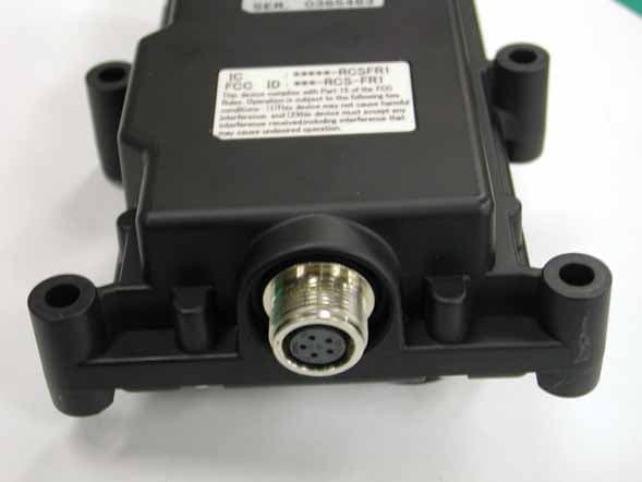
SU6-RCSFR1
Feb 07, 2005Remote Control Receiver for Crane
Equipment Class
CYY - Communications Receiver used w/Pt 15 Transmitter
SU6-RCSFT1
Feb 07, 2005Remote Control Transmitter for Crane
Equipment Class
DSC - Part 15 Security/Remote Control Transmitter