SUD-50RFMWireless Audio Device Module
Soundcast LLC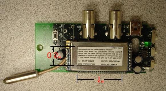
Click to zoom
Application Details
- Equipment Class
- DSS - Part 15 Spread Spectrum Transmitter
- Date of Grant
- Feb 03, 2008
- Application Purpose
- Original Equipment
- Date of Application
- Jan 31, 2008
- Equipment Note
- Wireless Audio Device Module
- Frequency Range
- 2403.30000000 - 2479.10000000
- Company
- Soundcast LLC
- Country
- United States
Documents & Files
Document Text
Text extracted from the exhibit documents filed with the FCC. Open a document above to read the original.
Users Manual
USER MANUAL SOUNDCAST 50RFM WIRELESS AUDIO SYSTEMS KSC INDUSTRIES, INC. 881 KUHN DIRVE, BUILDING 200 CHULA VISTA, CA 91914 1 TABLE OF CONTENT 1. GENERAL DESCRIPTION........................................................................................2 2. FEATURES...................................................................................................................2 3. ELECTRICAL SPECIFICATIONS...........................................................................3 3.1 OPERATING CONDITIONS – SOUNDCAST 50RFM TRANSMITTER.........................3 3.2 ABSOLUTE MAXIMUM RATINGS – SOUNDCAST 50RFM TRANSMITTER...............3 3.3 OPERATING CONDITIONS – SOUNDCAST 50RFM RECEIVER................................4 3.4 ABSOLUTE MAXIMUM RATINGS – SOUNDCAST 50RFM RECEIVER......................4 4. AUDIO CHARACTERISTICS...................................................................................5 5. RF CHARACTERISTICS..........................................................................................5 5.1 RF CHARACTERISTICS - SOUNDCAST 50RFM TRANSMITTER AND RECEIVER....5 6. PIN DESCRIPTION....................................................................................................6 6.1 PIN DESCRIPTION - SOUNDCAST 50RFM TRANSMITTER......................................6 6.2 PIN DESCRIPTION - SOUNDCAST 50RFM RECEIVER.............................................7 7. INFORMATION TO USER........................................................................................8 8. HUMAN EXPOSURE COMPLIANCE STATEMENT...........................................9 2 1. General Description SoundCast 50RFM is a complete point-to-point and point-to-multipoint wireless audio solution. SoundCast 50RFM takes a 2-channel digital stereo input signal, sends it across a robust radio frequency link, and then converts it back to a stereo analog signal for use at a remote location. SoundCast 50RFM is ideal for home theater rear speakers, headphones, public address systems, and outdoor speakers. 2. Features v Stereo Analog In/Analog Out, Digital In/Digital Out; v 92.4 dB SNR, 0.065% THD+N; v Digital volume control; v Auto Mute; v Digital Noise Gate; v 2.4 GHz wireless link, 1.536 Mbps data rate; v 50 m indoor range; v Each transmitter supports two receivers with stereo output from both receivers; v Up to 6 transmitters in one area; v Low latency (15 ms – 64 ms selectable); v Low power consumption; v Best in Class quality of service (QoS); v Duplex utility control channel; v Modules come with antenna soldered on for easy integration 3 3. Electrical Specifications 3.1 Operating Conditions – SoundCast 50RFM Transmitter Note: All Min/Max characteristics and specifications are guaranteed over the Specified operating conditions. Typical performance characteristics and specifications are derived from measurements taken at typical supply voltages and TA=25oC. 3.2 Absolute Maximum Ratings – SoundCast 50RFM Transmitter 4 3.3 Operating Conditions – SoundCast 50RFM Receiver 3.4 Absolute Maximum Ratings – SoundCast 50RFM Receiver 5 4. Audio Characteristics Notes: FS = Full Scale 1. All measurements are for 5 bit MPX encoding. 2. RX line out into a 10 kO Load. 3. All Tests Conducted with AES Filter “In” Unless Otherwise Specified. 5. RF Characteristics The SoundCast 50RFM algorithm is described below paying special attention to include information pertinent to FCC and ETSI regulations. The SoundCast 50RFM software operates by selecting a palette (or group) of 15 random channels out of the total 38 to hop on. For the 15- channel palette, any channels with poor transmission rates are replaced with better channels from the remaining 23 unused channels. The hopping pattern from channel to channel is a random pattern. The following table describes some important aspects of the channel-hopping algorithm: 5.1 RF Characteristics - SoundCast 50RFM Transmitter and Receiver 6 6. Pin Description 6.1 Pin Description - SoundCast 50RFM Transmitter 7 6.2 Pin Description - SoundCast 50RFM Receiver 8 7. Information to User This device complies with Part 15 of the FCC Rules. Operation is subject to the following two conditions: (1) This device may not cause harmful interference, and (2) This device must accept any interference received, including interference that may cause undesired operation. This equipment has been tested and found to comply with the limits for Class B Digital Device, pursuant to Part 15 of the FCC Rules. These limits are designed to provide reasonable protection against harmful interference in a residential installation. This equipment generates and can radiate radio frequency energy and, if not installed and used in accordance with the instructions, may cause harmful interference to radio communications. However, there is no guarantee that interference will not occur in a particular installation. If this equipment does cause harmful interference to radio or television reception, which can be determined by turning the 9 equipment off and on, the user is encouraged to try to correct the interference by one or more of the following measures. • Reorient or relocate the receiving antenna • Increase the separation between the equipment and receiver • Connect the equipment into an outlet on a circuit different from that to which the receiver is connected • Consult the dealer or an experienced radio/TV technician for help Any changes or modifications not expressly approved by the party responsible for compliance could void the user’s authority to operate the equipment. 8. Human Exposure Compliance Statement KSC Industries, Inc. certifies that it has determined that the 50RFM complies with the RF hazard requirements applicable to transmitting equipment operating under the authority of 47 CFR Part 15, Subpart C of the FCC Rules and Regulations. This determination is dependent upon installation, operation and use of the equipment in accordance with all instructions provided. The 50RFM is designed for and intended to …
Text truncated - open the document above for the full version.
Cover Letter(s)
11/28/07 KSC Industries, Inc, 881 Kuhn Drive Building 200 Chula Vista 91914, USA. Nemko Canada Inc 303 River Road Ottawa, Ontario, Canada K1V 1H2 Attn: Director of Certification FCC ID: SUD-50RFM IC: 5613A-50RFM Authority to Act as Agent On our behalf, I appoint Alan Laudani of Nemko USA Inc., 11696 Sorrento Valley Rd, San Diego, CA, USA to act as our agent in the preparation of this application for equipment certification. I certify that submitted documents properly describe the device or system for which equipment certification is sought. I also certify that each unit manufactured, imported or marketed, as the Federal Communication Commission’s regulations will have affixed to it a label identical to that submitted for approval with this application. For instances where our authorized agent signs the application for certification on our behalf, I acknowledge that all responsibility for complying with the terms and conditions for certification, as specified by Nemko Canada Inc, still resides with KSC Industries, Inc, 881 Kuhn Drive Building 200, Chula Vista 91914, USA. Dated this 28 Day of November 20 07 Agency agreement expiration date: 28 November, 2008 By: Jim Wei Signature Printed Title: Sr. Applications Engineer On behalf of : KSC Industries, Inc. Telephone: (619) 671-0110 ext 3039
Cover Letter(s)
11/28/07 KSC Industries, Inc, 881 Kuhn Drive Building 200 Chula Vista 91914, USA. Nemko 11696 Sorrento Valley Rd. San Diego CA, 92121 USA Re: Request of Confidentiality for FCC ID#: SUD-50RFM Pursuant to Sections 0.457(d)(I)(ii) and 0.459 of the Commission’s Rules, the Applicant hereby requests confidential treatment of information accompanying as outlined below: Schematics, Parts List, Operating Description, Block Diagrams The above materials contain trade secrets and proprietary information not customarily released to the public. The public disclosure of these matters might be harmful to the Applicant and provide unjustified benefits to its competitors. The Applicant understands that pursuant to Rule 0.457(d)(I)(ii), disclosure of this Application and all accompanying documentation will not be made before the date of the Grant for this Application. Sincerely, Jim Wei Sr. Applications Engineer KSC Industries, Inc.
Cover Letter(s)
11/28/07 KSC Industries, Inc, 881 Kuhn Drive Building 200 Chula Vista 91914, USA. Nemko Canada Inc 303 River Road Ottawa, Ontario, Canada K1V 1H2 Attn: Director of Certification Request for Limited Modular Approval for Soundcast 50RFM Dear Sir, We request limited modular approval of Soundcast 50RFM wireless audio system based on the following requirement in FCC Public Notice “Part 15 Unlicensed Modular Transmitter Approval”. Since the Soundcast 50RFM wireless audio system does not have its own power supply regulation as required in item number 3 of the FCC public notice, we will use the exact same power supply regulation used for the FCC certification test fixture in our products to ensure that the final products are compliant with FCC regulation. FCC requirement and KSC response: 1. The modular transmitter must have its own RF shielding. This is intended to ensure that the module does not have to rely upon the shielding provided by the device into which it is installed in order for all modular transmitter emissions to comply with Part 15 limits. It is also intended to prevent coupling between the RF circuitry of the module and any wires or circuits in the device into which the module is installed. Such coupling may result in non-compliant operation. KSC response: Soundcast 50RFM has its own RF shielding. 2. The modular transmitter must have buffered modulation/data inputs (if such inputs are provided) to ensure that the module will comply with Part 15 requirements under conditions of excessive data rates or over-modulation. KSC response: Soundcast 50RFM has an analog to digital converter that is fixed at 48 kbps data rate. 3. The modular transmitter must have its own power supply regulation. This is intended to ensure that the module will comply with Part 15 requirements regardless of the design of the power supplying circuitry in the device into which the module is installed. KSC response: Soundcast 50RFM does not have its own power supply regulation. The final product will have a motherboard for the Soundcast module that has the exact power supply regulation as on the test fixture. 4. The modular transmitter must comply with the antenna requirements of Section 15.203 and 15.204(c). The antenna must either be permanently attached or employ a “unique” antenna coupler (at all connections between the module and the antenna, including the cable). Any antenna used with the module must be approved with the module, either at the time of initial authorization or through a Class II permissive change. The “professional installation” provision of Section 15.203 may not be applied to modules. KSC response: The antenna for Soundcast 50RFM is permanently attached to the module and is included in the approval. 5. The modular transmitter must be tested in a stand-alone configuration, i.e., the module must not be inside another device during testing. This is intended to demonstrate that the module is capable of complying with Part 15 emission limits regardless of the device into which it is eventually installed. Unless the transmitter module will be battery powered, it must comply with the AC line conducted requirements found in Section 15.207. AC or DC power lines and data input/output lines connected to the module must not contain ferrites, unless they will be marketed with the module (see Section 15.27(a)). The length of these lines shall be length typical of actual use or, if that length is unknown, at least 10 centimetres to insure that there is no coupling between the case of the module and supporting equipment. Any accessories, peripherals, or support equipment connected to the module during testing shall be unmodified or commercially available (see Section 15.31(i)). KSC response: The modular transmitter is tested in a stand-along configuration. The AC and DC power line and data input/output lines connected to the module do not contain ferrites. The length of these lines is more than 10 centimetres. There is no any accessories, peripherals attached to the module except the test fixture that provides power supply regulation. 6. The modular transmitter must be labeled with its own FCC ID number, and, if the FCC ID is not visible when the module is installed inside another device, then the outside of the device into which the module is installed must also display a label referring to the enclosed module. This exterior label can use wording such as the following: “Contains Transmitter Module FCC ID: SUD- 50RFM” or “Contains FCC ID: SUD-50RFM.” Any similar wording that expresses the same meaning may be used. The Grantee may either provide such a label, an example of which must be included in the application for equipment authorization, or, must provide adequate instructions along with the module which explain this requirement. In the latter case, a copy of these instructions must be included in the application for equipment authorization. KSC response: There will be a label on the RF shield and there will be exterior label that has the wording “Contains FCC ID: SUD-50RFM”. 7. The modular transmitter must comply with any specific rule or operating requirements applicable to the transmitter and the manufacturer must provide adequate instructions along with the module to explain any such requirements. A copy of these instructions must be included in the application for equipment authorization. For example, there are very strict operational and timing requirements that must be met before a transmitter is authorized for operation under Section 15.231. For instance, data transmission is prohibited, except for operation under Section 15.231(e), in which case there are separate field strength level and timing requirements. Compliance with these requirements must be assured. KSC response: KSC will be fully responsible for the integration of final products for its customers for Soundcast modules. KSC will ensure that the final products using Soundcast module comply with rules applicable to the transmitter. 8.…
Text truncated - open the document above for the full version.
External Photos
The plastic case below protected the module during testing but is not part of the module in future use.
ID Label/Location Info
LABEL REQUIREMENTS RF IC & FCC KSC Industries, Inc. Model No.: 50RFM IC: 5613A-50RFM FCC ID: SUD-50RFM * This device complies with Part 15 of the FCC Rules. Operation is subject to the following two conditions: (1) This device may not cause harmful interference, and (2) This device must accept any interference received, including interference that may cause undesired operation. Made in China Label dimension: Length: 1” Height: 0.5” Appear on the typical mother board as shown in the picture below:
Internal Photos
The plastic case below protected the module during testing but is not part of the module in future use.
RF Exposure Info
Prediction of MPE limit at a given distance Equation from page 18 of OET Bulletin 65, Edition 97-01 where:S = power density P = power input to the antenna G = power gain of the antenna in the direction of interest relative to an isotropic radiator R = distance to the center of radiation of the antenna Maximum peak output power --Conducted20.72dBm 0.118(W) Antenna gain(typical):0.00(dBi) Maximum antenna gain:1.00(numeric) Prediction distance:20.00(cm) Prediction frequency:2442.00(MHz) Limit from table below:1(mW/cm^2) Power density at prediction frequency:0.023(mW/cm^2) EUT complies FCC/LSGAC Local Official’s Guide to RF A LOCAL GOVERNMENT OFFICIAL'S GUIDE TO TRANSMITTING ANTENNA RF EMISSION SAFETY: RULES, PROCEDURES, AND PRACTICAL GUIDANCE 2 4R PG S π =
Test Report
Nemko USA, Inc. 11696 Sorrento Valley Rd., Suite F San Diego, CA 92121-1024 Phone (858) 755-5525 Fax (858) 452-1810 CERTIFICATION TEST REPORT PART 15.247C IC RSS-210 For The Subcast Transmitter Model: 50FRM FCC ID: SUD-50FRM IC: 5613A-50RFM PREPARED FOR: KSC Industries, Inc. 881 Kuhn Drive Bldg 200 Chula Vista CA 91914 PREPARED ON 11-08-07 REPORT NUMBER: 2007 117840-FCC 7840-1 Total Pages: 28 Nemko USA, Inc. 11696 Sorrento Valley Road, Suite F, San Diego, CA 92121 Phone (858) 755-5525 Fax (858) 452-1810 DATE DOCUMENT NAME DOCUMENT # PAGE Nov. 8, 2007 50RFM Certification Test Report FCC ID: SUD-50FRM IC: 5613A-50RFM 2007 117840-FCC 2 of 28 DOCUMENT HISTORY REVISION DATE COMMENTS - 11-08-07 Prepared By: J. Garcia - 1-22-08 Initial Release: Alan Laudani NOTE: Nemko USA, Inc. hereby makes the following statements so as to conform to Chapter 10 (Test Reports) Requirements of ANSI C63.4 (2003) “Methods and Measurement of Radio-Noise Emissions from Low-Voltage Electrical and Electronic Equipment in the Range of 9 kHz to 40 GHz”: NOTE: Nemko USA, Inc. hereby makes the following statements so as to conform to Chapter 10 (Test Reports) Requirements of ANSI C63.4 (2003) “Methods and Measurement of Radio-Noise Emissions from Low-Voltage Electrical and Electronic Equipment in the Range of 9 kHz to 40 GHz”: o The unit described in this report was received at Nemko USA, Inc.'s facilities on March 11, 2004. Testing was performed on the unit described in this report on March 11, 2004 to March 16, 2004. o The Test Results reported herein apply only to the Unit actually tested, and to substantially identical Units. o This report does not imply the endorsement of the Federal Communications Commission (FCC), NVLAP or any other government agency. This Report is the property of Nemko USA, Inc., and shall not be reproduced, except in full, without prior written approval of Nemko USA, Inc. However, all ownership rights are hereby returned unconditionally to KSC Industries, Inc., and approval is hereby granted to KSC Industries, Inc., and its employees and agents to reproduce all or part of this report for any legitimate business purpose without further reference to Nemko USA, Inc. Nemko USA, Inc. 11696 Sorrento Valley Road, Suite F, San Diego, CA 92121 Phone (858) 755-5525 Fax (858) 452-1810 DATE DOCUMENT NAME DOCUMENT # PAGE Nov. 8, 2007 50RFM Certification Test Report FCC ID: SUD-50FRM IC: 5613A-50RFM 2007 117840-FCC 3 of 28 TABLE OF CONTENTS 1. ADMINISTRATIVE DATA AND TEST SUMMARY.............................................................................................5 1.1. ADMINISTRATIVE DATA.........................................................................................................................................5 2. SYSTEM CONFIGURATION....................................................................................................................................6 2.1. DESCRIPTION AND METHOD OF EXERCISING THE EUT....................................................................................6 2.2. SYSTEM COMPONENTS AND POWER CABLES......................................................................................................6 2.3. DEVICE INTERCONNECTION AND I/O CABLES.....................................................................................................6 2.4. DESIGN MODIFICATIONS FOR COMPLIANCE........................................................................................................6 3. DESCRIPTION OF TEST SITE AND EQUIPMENT..............................................................................................7 3.1. DESCRIPTION OF TEST SITE...................................................................................................................................7 4. DESCRIPTION OF TESTING METHODS..............................................................................................................8 4.1. INTRODUCTION.........................................................................................................................................................8 4.2. CONFIGURATION AND METHODS OF MEASUREMENTS FOR CONDUCTED EMISSIONS.................................8 4.3. CONFIGURATION AND METHODS OF MEASUREMENTS FOR FREQUENCY IDENTIFICATION......................9 4.4. CONFIGURATION AND METHODS OF MEASUREMENTS FOR RADIATED EMISSIONS...................................10 5. TEST RESULTS.........................................................................................................................................................11 5.1. CONDUCTED EMISSIONS TEST DATA – TRANSMIT MODE..............................................................................11 5.2. RECEIVE MODE........................................................................................................................................................12 5.3 RADIATED EMISSIONS TEST DATA –...................................................................................................................13 5.3. DUTY CYCLE MEASUREMENT.............................................................................................................................15 5.4. BANDWIDTH............................................................................................................................................................16 5.5. POWER LEVEL AND RADIATED SPURIOUS EMISSIONS.....................................................................................18 5.6. BANDEDGE EMISSIONS............................................................................................................................................19 5.7. NUMBER OF HOPPING CHANNELS........................................................................................................................24 5.8. CHANNEL SEPARATION.........................................................................................................................................25 5.9. TIME OF …
Text truncated - open the document above for the full version.
Test Setup Photos
Photograph 1. Conducted Emissions Test Configuration Photograph 2. Radiated Emissions Test Configuration
Contact Information
Applicant
Joan Mei(Product Engineer)
Technical Contact
KSC Industries, Inc.Jim Wei
[email protected](619) 671-0110
881 Kuhn Drive, Building 200 · Chula Vista, California · United States
Non-Technical Contact
KSC Industries, Inc.Jim Wei
[email protected](619) 671-0110
Test Firm
Nemko USA, Inc.Rhonda Saxon
Technical Specifications
| # | Rule Parts | Frequency Range | Power Output |
|---|---|---|---|
| 1 | 15C | 2.40 GHz - 2.48 GHz | 118.00 mW |
Other Applications from Soundcast LLC
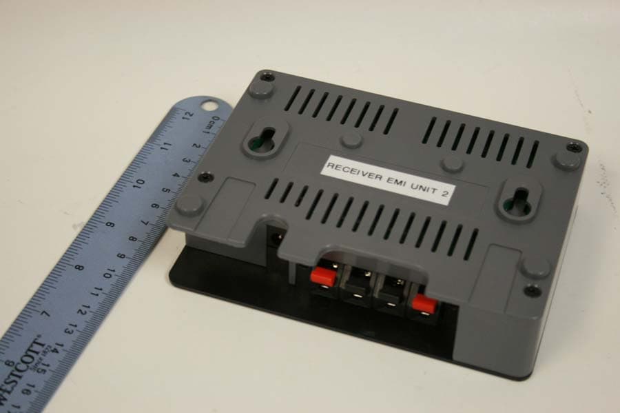
SUDSCR15M
Apr 26, 2010Wireless Surround System
Equipment Class
DSS - Part 15 Spread Spectrum Transmitter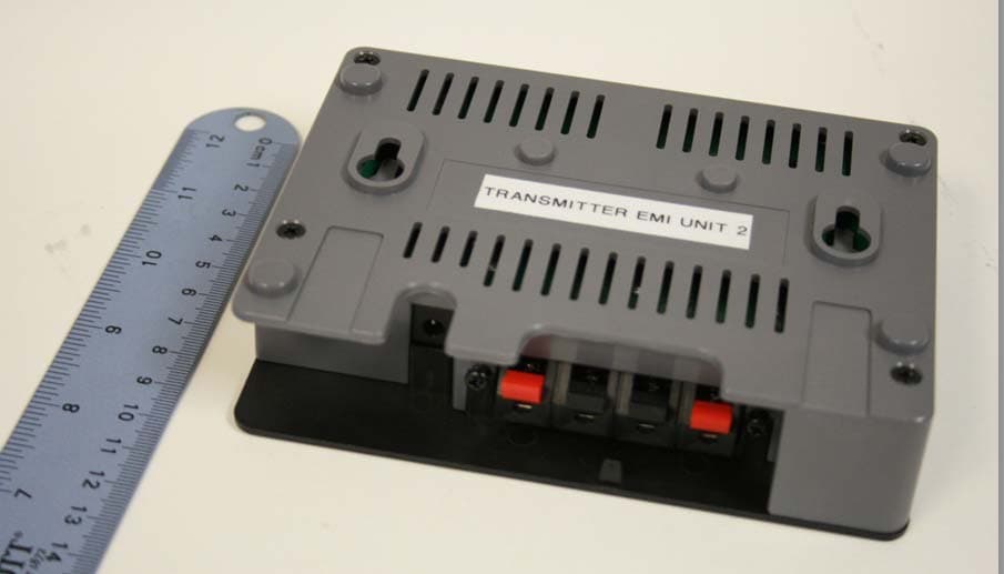
SUDSCT15M
Apr 15, 2010Wireless Surround System
Equipment Class
DSS - Part 15 Spread Spectrum Transmitter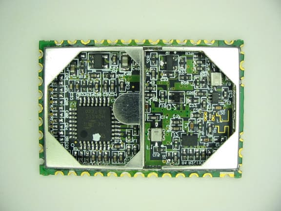
SUD-SCG2ER
May 18, 2006Wireless Audio Transmitter
Equipment Class
DSS - Part 15 Spread Spectrum Transmitter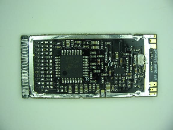
SUD-SCG2
May 18, 2006Wireless Audio Transmitter Module
Equipment Class
DSS - Part 15 Spread Spectrum Transmitter