SUDSCT15MWireless Surround System
Soundcast LLC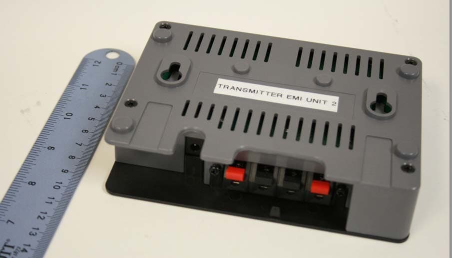
Click to zoom
Application Details
- Equipment Class
- DSS - Part 15 Spread Spectrum Transmitter
- Date of Grant
- Apr 15, 2010
- Application Purpose
- Original Equipment
- Date of Application
- Apr 15, 2010
- Equipment Note
- Wireless Surround System
- Frequency Range
- 2403.30000000 - 2479.00000000
- Company
- Soundcast LLC
- Country
- United States
Documents & Files
Document Text
Text extracted from the exhibit documents filed with the FCC. Open a document above to read the original.
Users Manual
Quick Install Instruction Before you start... • Read the instructions. • Do not install this system in close proximity to water or fire. • Do not expose these products to very hot environments or heat sources. • Use only the original parts and accessories provided by Soundcast Systems. • Avoid spilling liquids on any of the components of the system. • Clean using only a dry cloth. • This equipment is designed and intended for indoor use only. • To avoid a tripping hazard, do not place wires in exposed walkways. • Connect wires by inserting the stripped leads completely inside the spring terminals. Make sure there is no excess stripped wire outside of the spring terminal. Excess stripped wires left outside of spring terminals may cause a short circuit and prevent the unit from functioning properly. • Connect the SCT101 Transmitter (black front and grey enclosure) to the audio source with supplied input wires. Using speaker wire, connect the SCR102 Receiver (black front and enclosure) to your speakers. NOTE: This product uses a radio technology that is not compatible with other Soundcast Products. It is designed for the express purpose of in-room surround sound applications. CAUTION! Do not connect the SCR102 Receiver to the audio source. This will damage the Receiver and/or the audio source. 2 Safety information + Specifications 1 SCT101 Transmitter (Black front, grey enclosure) 1 SCR102 Receiver (Black front and enclosure) 1 SY-0630 115VAC / 6VDC Power Adapter for Transmitter 1 GPE603- 100 – 240VAC / 24VDC Power Adapter for Receiver, AC clip 1 Power Cord for GPE603 Power Adapter 2 Transmitter Input Wires (black / black - white pair) 2 Stands 1 SCS100 SurroundCast Kit Contents • Compact design • Works in the 2.4GHz frequency band • Co-exists with other 2.4GHz devices • Interference free audio operation • Designed for in-room transmission range • Very high quality audio SCT 101 Transmitter SCR 102 Receiver + - 1 2 3 4 56 + - 7 8 3 Features Please observe these guidelines to ensure the reliability and quality of the wireless connection. 1. For best results install both Transmitter and Receiver in a vertical orientation. 2. If the SurroundCast Receiver is wall mounted, optimum performance will occur if it is placed so that the orientation is facing the SurroundCast Transmitter. 3. If the SurroundCast Receiver is mounted in the mounting stand (included), optimum performance will occur if it is placed with an orientation facing the Sur- roundCast Transmitter. 4. It is also recommended to place both SurroundCast units at least 18 inches away from metallic walls or large metallic blocking objects to ensure a strong wireless link. 5. Prevent heavy objects from falling on the system and and/or exposed electrical wiring near SurroundCast components to avoid the risk of an electric shock. 6. Place SurroundCast components away from other sources of wireless signals such as routers, music networks or any other electronic piece of equipment that uses radio commu- nications including other Soundcast products. A distance of 3 ft. or more between SurroundCast and your other wireless devices is preferable for optimum performance. 4 Placement Home Theater Application Left Surround Right Surround Subwoofer Amplifier Left Center Right 5 Setup Transmitter and Receiver Units – 1 Positive (+) volume calibration control 2 Negative (-) volume calibration control 3 Status indicator 4 DC jack 5 Left speaker input terminals 6 Right speaker input terminals 7 Re-mating switch access 8 Wall mounting holes Black/Black Black/Gray SCT 101 Transmitter SCR 102 Receiver CAUTION CAUTION: Be certain that you are connecting the SCT101 Transmitter to your Home Theater System. Connecting the SCR102 Receiver to the Home Theater System could result in damage to SurroundCast and/or your Home Theater equipment. CAUTION Transmitter Audio input (speakers) .................. 10 VRMS MAX Audio output (wireless) ................. 48 kHz, 16-bit stereo Transmission delay ........................ 20 mS Power supply ................................ DC 6 V at 0.3 A Receiver Audio input (wireless) ................... 48 kHz, 16-bit stereo Audio output (speakers) ................ 50 W (RMS) Speakers ....................................... 4 to 8 ohm compatible Signal-to-noise ratio ..................... 100 dB Total harmonic distortion ............... < 0.5% Power supply ................................ DC 24 V at 2.5 A Power consumption ...................... 60 W Poster.indd 12/26/10 11:09:27 AM 1. Control of the volume will always be done using your Home Theater System volume control. The + and - controls on the SCT101 Transmitter and SCR102 Receiver are only to be used for system calibration, and should rarely need adjustment. 2. In most applications there will be no need to adjust the + and - volume calibration controls. These units have been factory calibrated to allow you to simply connect them and set the volume calibration with your Home Theater System’s setup function. However, if your Home Theater System setup function is unable to set the proper level, you may use the + and - volume calibration controls on the SCT101 or SCR102 during system setup by following these simple steps. a. The SCT101 Transmitter and SCR102 Receiver are both furnished with + and - volume calibration controls. The controls perform exactly the same function and are placed on both units for ease of setup in case one of the units is mounted in a place not easily accessible. b. Select the unit that is most accessible. To adjust the level, press the + or – button to the desired level. Once you have set the level, the SurroundCast system will automatically remember that setting and will not need further adjustment. 3. To reset the volume calibration to factory settings, remove power from the SCT101 Transmitter. Press and hold both the + and – buttons while restoring power, and hold the buttons down until the blue indicator starts flashing. 7 Connecting the Receiver …
Text truncated - open the document above for the full version.
Cover Letter(s)
881 Kuhn Drive, Building 200, Chula Vista, CA 91914 USA Phone: 619.671.0110 Fax: 619.671.0330 www.kscind.com 3/03/2010 Nemko Canada Inc 303 River Road Ottawa, Ontario, Canada K1V 1H2 Attn: Director of Certification FCC ID: SUDSCT15M Authority to Act as Agent On our behalf, I appoint Ferdinand Custodio of Nemko USA Inc., 11696 Sorrento Valley Rd, San Diego, CA, USA to act as our agent in the preparation of this application for equipment certification. I certify that submitted documents properly describe the device or system for which equipment certification is sought. I also certify that each unit manufactured, imported or marketed, as defined in Federal Communication Commission’s regulations will have affixed to it a label identical to that submitted for approval with this application. For instances where our authorized agent signs the application for certification on our behalf, I acknowledge that all responsibility for complying with the terms and conditions for certification, as specified by Nemko Canada Inc, still resides with KSC Industries, Inc. 881 Kuhn Dr. Building 200, Chula Vista, CA 91914, expiring September 3 rd 2010. Sincerely, Michael England Senior Audio Systems Engineer KSC Industries, Inc.
Cover Letter(s)
881 Kuhn Drive, Building 200, Chula Vista, CA 91914 USA Phone: 619.671.0110 Fax: 619.671.0330 www.kscind.com 3/03/2010 Nemko Canada Inc. 303 River Road Ottawa, Ontario, Canada K1V 1H2 Re: Request of Confidentiality for FCC ID#: SUDSCT15M Pursuant to Sections 0.457(d)(I)(ii) and 0.459 of the Commission’s Rules, the Applicant hereby requests confidential treatment of information accompanying as outlined below: Schematics, Parts List, Operating Description, Block Diagrams The above materials contain trade secrets and proprietary information not customarily released to the public. The public disclosure of these matters might be harmful to the Applicant and provide unjustified benefits to its competitors. The Applicant understands that pursuant to Rule 0.457(d)(I)(ii), disclosure of this Application and all accompanying documentation will not be made before the date of the Grant for this Application. Sincerely, Michael England Senior Audio Systems Engineer KSC Industries, Inc.
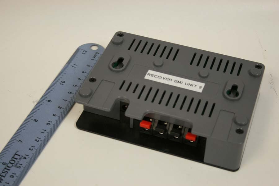
External Photos
FCC ID: SUDSCT15M IC: 5613A-SCT15M
ID Label/Location Info
THIS PRINT DISCLOSES SUBJECT MATTER IN WHICH SOUNDCAST HAS PROPRIETARY RIGHTS. THE RECEIPT OR POSSESSION OF THIS PRINT DOES NOT CONFER, TRANSFER OR LICENSE THE USE OF THE DESIGN OR TECHNICAL INFORMATION SHOWN HEREIN, REPRODUCTION OF THIS PRINT OR ANY INFORMATION CONTAINED HEREIN OR MANUFACTURE OF ANY ARTICLE HEREFROM, FOR DISCLOSURE TO OTHERS, IS FORBIDDEN, EXCEPT BY SPECIFIC WRITTEN PERMISSION FROM SOUNDCAST. DATE DATE DATE DIMENSIONS AND TOLERANCES THIRD PLANE PROJECTION UNLESS OTHERWISE SPECIFIED ARE IN MM: X.XX± X.X± X.XXX± METRICANG. ± APP. BY: CHECKED BY DRAWN BY:DRAWN BY: USED ON: REF. NO: DWG. NO: SCALE: SIZE TITLE: CUST. NO: REV SHEET A 0.5 0.20 0.050 0° 30' -- ------ ----- 2-10-10 ---- ---- D. Belanger Surroundcast Tx Label X5 1 OF 1 NTS ---- 2-250-076-01 NOTES BAR CODE IN 128 CODE 1. 869 = SURROUNDCAST 2. YY = YEAR OF MANUFACTURE 10 = 2010 11 = 2011 12 = 2012 ETC. 3. MM = MONTH OF MANUFACTURE 01 = JAN 02 = FEB 03 = MAR ETC. 4. 1XXXX 10001 10002 10003 ETC. Version: 1.0.2 Made in CN FCC ID: SUDSCT15M IC: 5613A-SCT15M Model: SCT101
Internal Photos
FCC ID: SUDSCT15M IC: 5613A-SCT15M
RF Exposure Info
Prediction of MPE limit at a given distance Equation from page 18 of OET Bulletin 65, Edition 97-01where: S = power density P = power input to the antennaG = power gain of the antenna in the direction of interest relative to isotropicR = distance to the center of radiation of the antenna 0.02924 Maximum peak output power at antenna input terminal: 14.66 (dBm) Maximum p eak out p ut p ower at antenna in p ut terminal: 29.24 ( mW ) 2 4 R PG S π = Maximum peak output power at antenna input terminal: 29.24 (mW) Antenna gain(typical): 3.3 (dBi) Maximum antenna gain: 2.138 (numeric) Prediction distance: 20 (cm) Sourse Based Time Average Duty Cycle: 100 (%) Prediction frequency: 2442.2 (MHz) MPE limit for uncontrolled exposure at prediction frequency: 1.000 (mW/cm^2) Power density at prediction frequency: 0.0124 (mW/cm^2) Power density at prediction frequency: 0.124 (W/m^2) Margin of Compliance: -19.05 (dB) 2 4 R PG S π =
Test Report
Nemko USA, Inc. 11696 Sorrento Valley Rd., Suite F San Diego, CA 92121-1024 Phone (858) 755-5525 Fax (858) 452-1810 FCC Part 15 Subpart C, 15.247 : 14/04/2010 CERTIFICATION TEST REPORT Report Number: 2010 02301489 TX FCC Project Number: 23972 Nex Number: 301489 Applicant: KSC INDUSTRIES INC. 881 KUHN DRIVE BUILDING 200 Chula Vista, CA 91914 Equipment Under Test (EUT): WIRELESS SURROUND SYSTEM Model: SCT101 FCC ID: SUDSCT15M IC: 5613A-SCT15M In Accordance With: FCC Part 15 Subpart C, 15.247 IC RSS-210 Issue 7 June 2007 IC RSS-Gen Issue 2 June 2007 Tested By: Nemko USA Inc. 11696 Sorrento Valley Road, Suite F San Diego, CA 92121 Authorized By: Alan Laudani, EMC/RF Test Engineer Date: March 1, 2010 Total Number of Pages: 55 Nemko USA, Inc. 11696 Sorrento Valley Road, Suite F, San Diego, CA 92121 Phone (858) 755-5525 Fax (858) 452-1810 FCC ID: SUDSCT15M Report Number: 2010 02301489 TX FCC IC: 5613A-SCT15M Specification: FCC Part 15 Subpart C, 15.247 Page 2 of 55 Section1: Summary of Test Results General All measurements are traceable to national standards These tests were conducted on a sample of the equipment for the purpose of demonstrating compliance with FCC Part 15; Subpart C and IC RSS-210. Radiated tests were conducted is accordance with ANSI C63.4-2003. Radiated emissions are made on an open area test site. A description of the test facility is on file with the FCC and IC. The assessment summary is as follows: Apparatus Assessed: Wireless Surround System Model: SCT101 Specification: FCC Part 15 Subpart C, 15.247 IC RSS-210 Issue 7 June 2007 Date Received in Laboratory: February 19, 2010 Compliance Status: Complies Exclusions: None Non-compliances: None Nemko USA, Inc. 11696 Sorrento Valley Road, Suite F, San Diego, CA 92121 Phone (858) 755-5525 Fax (858) 452-1810 FCC ID: SUDSCT15M Report Number: 2010 02301489 TX FCC IC: 5613A-SCT15M Specification: FCC Part 15 Subpart C, 15.247 Page 3 of 55 1.1 Report Release History REVISION DATE COMMENTS - March 1, 2010 Prepared By: Ferdinand Custodio - March 1, 2010 Initial Release: Alan Laudani Note that the results contained in this report relate only to the items tested and were obtained in the period between the date of initial receipt of samples and the date of issue of the report. This test report has been completed in accordance with the requirements of ISO/IEC 17025. Nemko USA Inc. authorizes the applicant to reproduce this report provided it is reproduced in its entirety and for use by the company’s employees only. Any use which a third party makes of this report, or any reliance on or decisions to be made based on it, are the responsibility of such third parties. Nemko USA Inc. accepts no responsibility for damages, if any, suffered by any third party as a result of decisions made or actions based on this report. TESTED BY: ___________________________________ Date: March 1, 2010 Ferdinand Custodio, EMC Test Engineer Nemko USA, Inc. 11696 Sorrento Valley Road, Suite F, San Diego, CA 92121 Phone (858) 755-5525 Fax (858) 452-1810 FCC ID: SUDSCT15M Report Number: 2010 02301489 TX FCC IC: 5613A-SCT15M Specification: FCC Part 15 Subpart C, 15.247 Page 4 of 55 TABLE OF CONTENTS Section1: Summary of Test Results ............................................................................ 2 1.1 Report Release History ..................................................................................... 3 Section 2: Equipment Under Test ................................................................................ 5 2.1 Product Identification ........................................................................................ 5 2.2 Samples Submitted for Assessment ................................................................. 5 2.3 Theory of Operation .......................................................................................... 6 2.4 Technical Specifications of the EUT ................................................................. 6 Section 3: Test Conditions ........................................................................................... 7 3.1 Specifications .................................................................................................... 7 3.2 Deviations From Laboratory Test Procedures ................................................... 7 3.3 Test Environment .............................................................................................. 7 3.4 Test Equipment ................................................................................................. 8 Section 4: Observations ............................................................................................... 9 4.1 Modifications Performed During Assessment ................................................... 9 4.2 Record Of Technical Judgements ..................................................................... 9 4.3 EUT Parameters Affecting Compliance ............................................................ 9 4.4 Test Deleted ...................................................................................................... 9 4.5 Additional Observations .................................................................................... 9 Section 5: Results Summary ...................................................................................... 10 5.1 Test Results .................................................................................................... 10 Appendix A: Test Results ........................................................................................... 11 Section 15.207(a) – Power Line Conducted Emissions................................................. 11 Section 15.247(a)(1) – Carrier Frequency Separation................................................... 16 Section 15.247(a)(1)(iii) – Number of Hopping Frequencies ......................................... 18 Section 15.247(a)(1)(iii) – Time of Occupancy (Dwell Time) ......................................... 20 Section…
Text truncated - open the document above for the full version.
Test Setup Photos
FCC ID: SUDSCT15M IC: 5613ASCT15M
Contact Information
Applicant
Joan Mei(Product Engineer)
Technical Contact
KSC Industries, Inc.Michael England
[email protected](619) 671-0110
881 Kuhn Drive, Building 200 · Chula Vista, California · United States
Non-Technical Contact
KSC Industries, Inc.William McCarty
[email protected](619) 671-0110
Test Firm
Nemko USA, Inc. - San Diego EMC DivisionJan Blomgren
[email protected]760-444-3500
Technical Specifications
| # | Rule Parts | Frequency Range | Power Output |
|---|---|---|---|
| 1 | 15C | 2.40 GHz - 2.48 GHz | 29.24 mW |
Other Applications from Soundcast LLC
SUDSCR15M
Apr 26, 2010Wireless Surround System
Equipment Class
DSS - Part 15 Spread Spectrum Transmitter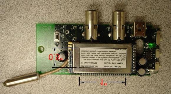
SUD-50RFM
Feb 03, 2008Wireless Audio Device Module
Equipment Class
DSS - Part 15 Spread Spectrum Transmitter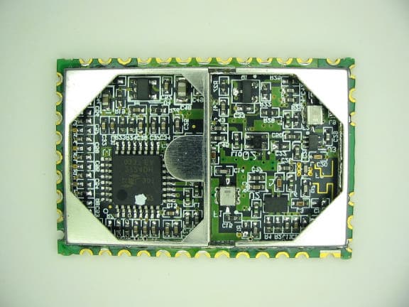
SUD-SCG2ER
May 18, 2006Wireless Audio Transmitter
Equipment Class
DSS - Part 15 Spread Spectrum Transmitter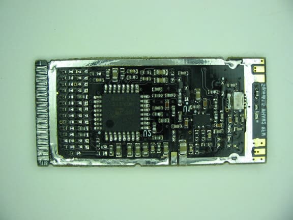
SUD-SCG2
May 18, 2006Wireless Audio Transmitter Module
Equipment Class
DSS - Part 15 Spread Spectrum Transmitter