SV8T-518Two Way Radio
Quanzhou YANTON Electronics Co., Ltd.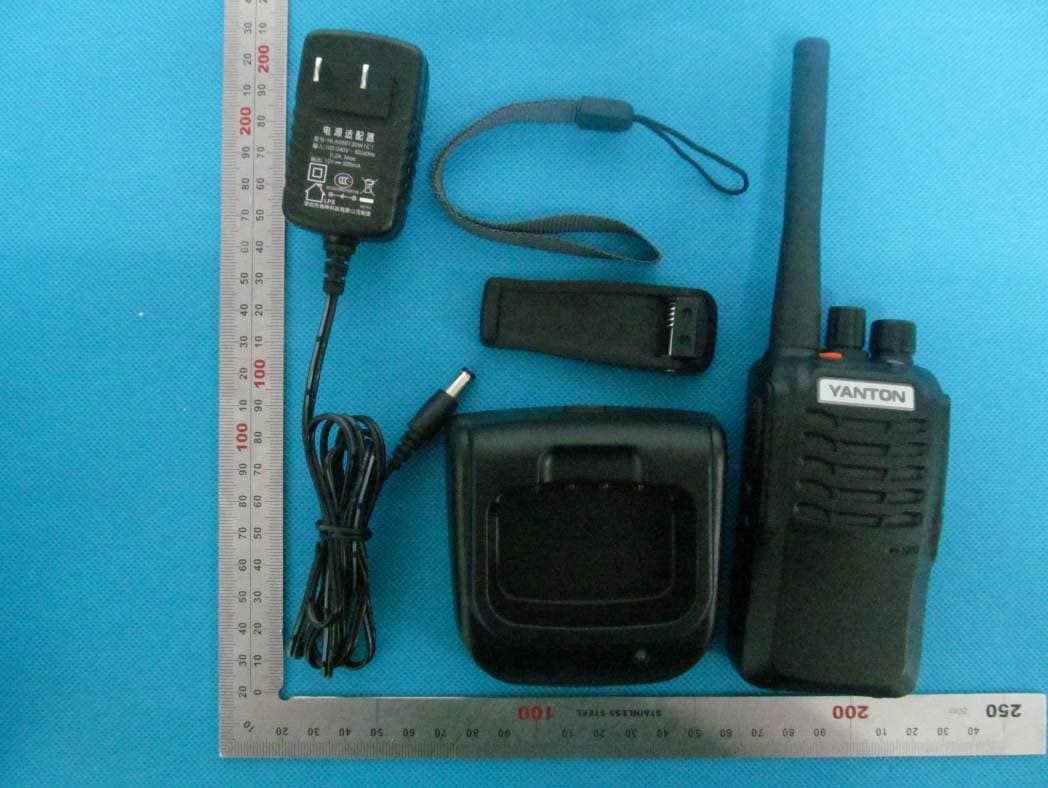
Click to zoom
Application Details
- Equipment Class
- TNF - Licensed Non-Broadcast Transmitter Held to Face
- Date of Grant
- May 09, 2013
- Application Purpose
- Original Equipment
- Date of Application
- May 08, 2013
- Equipment Note
- Two Way Radio
- Frequency Range
- 406.10000000 - 470.00000000
- Country
- China
Documents & Files
Document Text
Text extracted from the exhibit documents filed with the FCC. Open a document above to read the original.
Users Manual
User Manual Two Way Radio Brand Name: YANTON Model Name: T‐518 FCC ID: SV8T‐518 Introduction Thank you for purchasing Series Radio. The Series radios provide cost effective communications for businesses, they are the perfect communications solution for all of todays fast-paced industries. Please read this guide carefully so you know how to properly operate the radio before use. Safety and General Information Important Information on Safe and Efficient Operation. Read This information Before Using Your Radio. The information provided in this document supersedes the general safety information contained in user guides published before. Transmit and Receive Procedure Your two-way radio contains a transmitter and a receiver. To control your exposure and ensure compliance with the occupational/ controlled environment exposure limits, always adhere to the following procedure: ◆ Transmit no more than 50% of the time. ◆ To transmit (talk), press the Push to Talk (PTT) button. ◆ To receive calls, release the PTT button. Transmitting 50% of the time, or less, is important because the radio generates measurable RF energy exposure only when transmitting (in terms of measuring standards compliance). Portable Radio Operation and EME Exposure Antenna Care Use only the supplied or an approved replacement antenna. DO NOT hold the antenna when the radio is "IN USE" Holding the antenna affects the effective range. Two-Way Radio Operation When using your radio as a traditional two-way radio, hold the radio in a vertical position with the microphone 1 to 2 inches (2.5 to 5 cm) away from the lips. Body-Worn Operation If you wear a radio on your body when transmitting, always place the radio in a supplied or approved clip, holder, holster, case, or body harness for this product. If you do not use one of the supplied or approved body-worn accessories, and are not using the radio held in the normal use position, ensure the radio and its antenna are at least 1 inch (2.5 cm) from your body when transmitting. Data Operation If applicable, when using any data feature of the radio with or without an accessory cable, position the radio and its antenna at least 1 inch (2.5 cm) from the body. Electromagnetic Interference/Compatibility Note: Nearly every electronic device is susceptible to electromagnetic interference (EMI) if inadequately shielded, designed, or otherwise configured for electromagnetic compatibility. Facilities To avoid electromagnetic interference and/or compatibility conflicts, turn off your radio in any facility where posted notices instruct you to do so. Hospitals or health care facilities may be using equipment that is sensitive to external RF energy. Aircraft When instructed to do so, turn off your radio when on board' an aircraft. Any use of a radio must be in accordance with applicable regulations per airline crew instructions. Medical Devices Pacemakers The Advanced Medical Technology Association recommends that a minimum separation of 6 inches (15 cm) be maintained between a handheld wireless radio and a pacemaker. These recommendations are consistent with the independent research by,and recommendations of the U.S. Food and Drug Administration. Persons with pacemakers should: ◆ ALWAYS keep the radio more than six inches (15 cm) from their pacemaker when the radio is turned ON. ◆ Not carry the radio In the breast pocket. ◆ Use the ear opposite the pacemaker to minimize the potential for interference. ◆ Turn the radio OFF immediately if you have any reason to suspect that interference is taking place. Hearing Aids Some digital wireless radios may interfere with some hearing aids. In the event of such interference, you may want to consult your hearing aid manufacturer to discuss alternatives. Other Medical Devices If you use any other personal medical device, consult the manufacturer of your device to determine if it is adequately shielded form RF energy. Your physician may be able to assist you in obtaining this information. Safety and General Use While Driving Check the laws and regulations on the use of radios in the area where you drive. Always obey them. When using your radio while driving, please: ◆ Give full attention to driving and to the road. ◆ Use hands-free operation, if available. Pull off the road and park before making or answering a call if driving conditions so require. Operational Warnings ! Warnings ◆ For Vehicles with an Air Bag Do not place a portable radio in the area over an air bag or in the air bag deployment area. Air bags inflate with great force. If a portable radio is placed in the air bag deployment area and the air bag inflates, the radio may be propelled with great force and cause serious injury to occupants of the vehicle. ◆ Potentially Explosive Atmospheres Turn off your radio prior to entering any area with a potentially explosive atmosphere, unless it is a radio type especially qualified for use in such areas as "Intrinsically Safe." Do not remove, install, or charge batteries in such areas. Sparks in a potentially explosive atmosphere can cause an explosion or fire resulting in bodily injury or even death. Note: The areas with potentially explosive atmospheres referred to above include fueling areas such as below decks on boats, fuel or chemical transfer or storage facilities, areas where the air contains chemicals or particles, such as grain, dust or metal powders, and any other area where you would normally be advised to turn off your vehicle engine. Areas with potentially explosive atmospheres are often but not always posted. ◆ Blasting Caps and Areas To avoid possible interference with blasting operations, turn off your radio when you are near electrical blasting caps, in a blasting area, or in areas posted: "Turn off two-way radio. Obey all signs and instructions. Operational Cautions Antennas Do not use any portable radio that has a damaged antenna. If a damaged antenna comes into contact with your skin, a minor burn can result. Batteries All batteries can…
Text truncated - open the document above for the full version.
Cover Letter(s)
April 18, 2013 PHOENIX TESTLAB GmbH Koenigswinkel 10 D‐32825 Blomberg, Germany Subject: FCC ID: SV8T-518 Attestation statement that the end user can’t tune the transmitter. Gentlemen; The equipment meets the requirements of the FCC Rules, Part 90.203(e) and (g), as applicable. Programming of this product’s transmit frequencies can be performed ONLY by the manufacturer or by service or maintenance personal. The operator cannot be program transmit frequencies using the equipment’s external operation controls. Quanzhou YANTON Electronics Co.,Ltd. Alen Chen\G.M.
Cover Letter(s)
April 18, 2013 Federal Communication Commission Authorization and Evaluation Division FCC ID: SV8T-518 Re: Confidentiality Request Pursuant to Sections 0.457 and 0.459 of the Commission’s Rules, the applicant hereby requests confidential treatment of information applied this application as outlined below: 1: Block Diagram 2: Circuit Diagram 3: Operational Description 4: Parts List 5:Tune Up Procedure The above materials contain trade secrets and proprietary information not customarily released to the public. The public disclosure of these matters might be harmful to the applicant and provide unjustified benefits to its competitors. The Applicant understands that pursuant to Rules 0.457, disclosure of this Application and all accompanying documentation will not be made before the date of the Grant for this application. Sincerely, Quanzhou YANTON Electronics Co.,Ltd. Alen Chen\G.M.
Cover Letter(s)
April 18, 2013 Federal Communications Commission Authorization & Evaluation Division 7435 Oakland Mills Road Colombia, Maryland 21046 Subject: FCC ID: SV8T‐518 Justification Letter for Expanded Frequency Range 400‐470 MHz Gentlemen; You have asked Quanzhou YANTON Electronics Co.,Ltd. for justification to have the freq range 400‐470 MHz appears on the face of the FCC Grant of Certification for a Part 90 Certification. This frequency range is regarded as usual & customary by United States Federal Government and its various departments, user organizations and the military to appear on the face of the equipment Grant of Certification. (1) Quanzhou YANTON Electronics Co., Ltd.’s Marketing Department plans to ensure that USA users, other than those specifically identified in this letter, not operate within bands 400‐406 MHz, as controlled by the users’ FCC station license. (2) This device will not be marketed to USA users, other than those identified in the letter, namely the US Government and its various departments & military, for operation in 400‐406 MHz frequency range. Sincerely, Quanzhou YANTON Electronics Co., Ltd. Alen Chen\G.M.
Cover Letter(s)
Quanzhou YA N TO N Electronics Co.,Ltd. YANTON Building, Jinxia Road, Xiamei Town, Nan’an City, Fujian Province, China Date: April 18, 2013 Statement We, Quanzhou YANTON Electronics Co.,Ltd. states that our device, FCC ID: SV8T‐518, has no space to put the label except the battery compartment of this device. It is visible to the users as they purchase the products and install the battery. Sincerely yours, Alen Chen\G.M.
External Photos
External Photos TOTAL VIEW OF EUT TOP VIEW OF EUT BOTTOM VIEW OF EUT FRONT View of EUT BACK VIEW OF EUT LEFT VIEW OF EUT RIGHT VIEW OF EUT
ID Label/Location Info
FCC ID Label Location Product Name FCC RF Warning Label Two Way Radio FCC ID : SV8T‐518 Brand :YANTON Model : T‐518 Frequency Range : 400MHz to 470MHz
Internal Photos
Internal Photos OPEN VIEW-1 OF EUT OPEN VIEW-2 OF EUT INTERNAL VIEW-1 OF EUT INTERNAL VIEW-2 OF EUT INTERNAL VIEW-3 OF EUT
RF Exposure Info
FCC ID APPLIC Produc Brand Model Client Date of STAND REPOR A CAUTIO This rep laborato CATION PUR ct Designati Name Name f Issue DARD(S) RT VERSION Attestat ON: port shall n ory and sha SA : RPOSE ion : : : : : : : tion of G ot be repro all not be q R Te Report N SV8T-518 Original E Two Way YANTON T‐518 Quanzho u Apr.11, 2 0 FCC Oet6 5 IEEE Std. 47CFR § 2 V1.0 Global C oduced exc uoted out o est o.: AGC21 Equipment Radio u YANTON El 013 5 Supplemen 1528‐2003 2.1093 Complia cept in full w of context. Rep 14130401 lectronics Co nt C June 200 ance(Sh without the Re port 1S1 o., Ltd. 01 henzhen e written p eport No.: A t n) Co., L ermission AGC2141304 Page 1 Ltd. of the test 01S1 of 64 Report No.: AGC214130401S1 Page 2 of 64 Report Revise Record Report Version Revise Time Issued Date Valid Version Notes V1.0 / Apr.11, 2013 Valid Original Report Applica Applica Manufa Manufa Product Brand N Model N Differen EUT Vo Applica Te s t Da Te s t Re Perform Report T nt Name nt Address cturer Name cturer Addre t Name Name Name nce Descript oltage ble Standard ate esults med Location Template Tes Q Y A P e Q ess Y A P Tw YA T- tion N/ D d FC IE 47 A M 5. (M n A t 2F G A Docume Check Authoriz st Rep Quanzhou YA ANTON Bu rovince, Ch i Quanzhou YA ANTON Bu rovince, Ch i wo Way Rad ANTON -518 /A C7.4V by ba CC Oet65 S EEE Std. 152 7CFR § 2. pr.11, 2013 MAX SAR ME .993 W/Kg Maximum Sc ttestation of F, Building ushu, Xixia n GCRT-US-P nted By ked By zed By port C ANTON Elec ilding, Jinxi ina. ANTON Elec ilding, Jinxi ina. dio attery Supplement 28-2003 .1093 EASUREME (with 50% caling SAR = fGlobal Com 2, No.1-No ng Street, B PPT2/SAR (2 Vivi Ze Angela Solger Z Certific ctronics Co., a Road , X ctronics Co., a Road , X C June 200 ENT(1g) % duty cycle) = 6.001 W/K mpliance (Sh o.4, Chaxi ao'an Distri c 2013-03-01 eng a Li Zhang Re cation , Ltd. Xiamei Tow , Ltd. Xiamei Tow 1 ) Kg) henzhen) Co Sanwei Tec ct, Shenzhe ) Apr.11, 201 Apr.11, 201 Apr.11, 201 eport No.: A n n ,Nan'an C n ,Nan'an C o., Ltd. chnical Indu n, China 3 3 3 AGC2141304 Page 3 City, Fujian City, Fujian ustrial Park, 01S1 of 64 Report No.: AGC214130401S1 Page 4 of 64 TABLE OF CONTENTS 1. GENERAL INFORMATION ............................................................................................................................ 5 1.1. EUT Description .................................................................................................................................... 5 1.2. Test Procedure ...................................................................................................................................... 6 1.3. Test Environment ................................................................................................................................... 6 2. SAR MEASUREMENT SYSTEM ..................................................................................................................... 7 2.1. COMOSAR System Description ............................................................................................................ 7 2.2. COMOSAR E-Field Probe ..................................................................................................................... 9 2.3 Robot ..................................................................................................................................................... 9 2.4. Video Positioning System .................................................................................................................... 10 2.5. Device Holder...................................................................................................................................... 10 2.6. Elliptic Phantom ................................................................................................................................... 11 3. TISSUE SIMULATING LIQUID ..................................................................................................................... 12 3.1. The composition of the tissue simulating liquid ..................................................................................... 12 3.2. Tissue Calibration Result ..................................................................................................................... 13 3.3. Tissue Dielectric Parameters for Head and Body Phantoms ................................................................. 14 4. SAR MEASUREMENT PROCEDURE ......................................................................................................... 15 4.1. SAR System Validation ........................................................................................................................ 15 4.2. SAR Measurement Procedure ............................................................................................................. 17 5. SAR EXPOSURE LIMITS ............................................................................................................................ 18 6. TEST EQUIPMENT LIST ............................................................................................................................. 19 7. MEASUREMENT UNCERTAINTY ................................................................................................................ 20 8. CONDUCTED POWER MEASUREMENT .................................................................................................... 21 9. TEST RESULTS .......................................................................................................................................... 22 9.1. SAR Test Results Summary ................................................................................................................ 22 APPENDIX A. SAR SYSTEM VALIDATION DATA .......................................................................................... 24 APPENDIX B. SAR MEASUREMENT DATA .................................................................................................…
Text truncated - open the document above for the full version.
Test Report
Report No.: AGC214130401F2 Page 1 of 50 FCC Part 90 Test Report Report No.: AGC214130401F2 FCC ID : SV8T‐518 PRODUCT DESIGNATION : Two Way Radio BRAND NAME : YANTON MODEL NAME : T‐518 CLIENT : Quanzhou YANTON Electronics Co., Ltd. DATE OF ISSUE : Apr.16, 2013 STANDARD(S) : FCC Part 90 Rules REPORT VERSION : V 1.0 Attestation of Global Compliance (Shenzhen) Co., Ltd CAUTION: This report shall not be reproduced except in full without the written permission of the test laboratory and shall not be quoted out of context. Report No.: AGC214130401F2 Page 2 of 50 Report Revise Record Report Version Revise Time Issued Date Valid VersionNotes V1.0 / Apr.16, 2013 Valid Original Report Report No.: AGC214130401F2 Page 3 of 50 VERIFICATION OF COMPLIANCE Applicant: Quanzhou YANTON Electronics Co., Ltd. YANTON Building, Jinxia Road, Xiamei Town, Nan'an City, Fujian Province, China. Manufacturer: Quanzhou YANTON Electronics Co., Ltd. YANTON Building, Jinxia Road, Xiamei Town, Nan'an City, Fujian Province, China. Product Designation: Two Way Radio Brand Name: YANTON Model Name: T-518 Hardware Version: N/A Software Version: VER08.01 Report No.: AGC214130401F2 Date of Test: Apr.09, 2013 to Apr.14, 2013 WE HEREBY CERTIFY THAT: The above equipment was tested by Attestation of Global Compliance (Shenzhen) Co., Ltd. The data evaluation, test procedures, and equipment configurations shown in this report were made in accordance with the procedures given in ANSI C 63.4:2003. The sample tested as described in this report is in compliance with the FCC Rules Part 90 requirements The test results of this report relate only to the tested sample identified in this report. Tested by Wall Huang Apr.16, 2013 Checked By Forrest Lei Apr.16, 2013 Authorized By Solger Zhang Apr.16, 2013 Report No.: AGC214130401F2 Page 4 of 50 TABLE OF CONTENTS 1. GENERAL INFORMATION .................................................................................................................. 6 1.1 PRODUCT DESCRIPTION ............................................................................................................. 6 1.3 TEST METHODOLOGY ................................................................................................................. 7 1.4 TEST FACILITY .............................................................................................................................. 7 1.5 SPECIAL ACCESSORIES .............................................................................................................. 7 1.6 EQUIPMENT MODIFICATIONS ..................................................................................................... 7 2. SYSTEM TEST CONFIGURATION ..................................................................................................... 8 2.1 EUT CONFIGURATION .................................................................................................................. 8 2.2 EUT EXERCISE ............................................................................................................................. 8 2.3 GENERAL TECHNICAL REQUIREMENTS .................................................................................... 8 2.4 CONFIGURATION OF TESTED SYSTEM .................................................................................... 8 3. SUMMARY OF TEST RESULTS ......................................................................................................... 9 4. DESCRIPTION OF TEST MODES ..................................................................................................... 10 5. CONDUCTED LIMITS ........................................................................................................................ 11 5.1 PROVISIONS APPLICABLE ......................................................................................................... 11 5.2 MEASUREMENT PROCEDURE .................................................................................................. 11 5.3 TEST SETUP BLOCK DIAGRAM ................................................................................................. 12 5.4 TEST EQUIPMENT USED ............................................................................................................ 12 5.5 TEST RESULT .............................................................................................................................. 13 6. FREQUENCY TOLERANCE .............................................................................................................. 15 6.1 PROVISIONS APPLICABLE ......................................................................................................... 15 6.2 MEASUREMENT PROCEDURE .................................................................................................. 15 6.3 TEST SETUP BLOCK DIAGRAM ................................................................................................. 16 6.4 TEST EQUIPMENT USED: ........................................................................................................... 16 6.5 TEST RESULT .............................................................................................................................. 16 7. EMISSION BANDWIDTH ................................................................................................................... 20 7.1 PROVISIONS APPLICABLE ......................................................................................................... 20 7.2 MEASUREMENT PROCEDURE .................................................................................................. 20 7.3 TEST SETUP BLOCK DIAGRAM ................................................................................................. 20 7.4 MEASUREMENT EQUIPMENT USED: ........................................................................................ 20 7.5 MEASUREMENT RESULT: ............................................................................................…
Text truncated - open the document above for the full version.
Test Setup Photos
Test Setup Photos RADIATED TEST SETUP CONDUCTED EMISSION TEST SETUP
Contact Information
Applicant
Alen Chen
Test Firm
Attestation of Global Compliance Shenzhen Co. Ltd.Forrest Lei
Technical Specifications
| # | Rule Parts | Frequency Range | Power Output | Emission | Tolerance |
|---|---|---|---|---|---|
| 2 | 9 | 406.1 MHz - 470 MHz | 4.955 W | 8K01F3E | 0.24 ppm |
Other Applications from Quanzhou YANTON Electronics Co., Ltd.
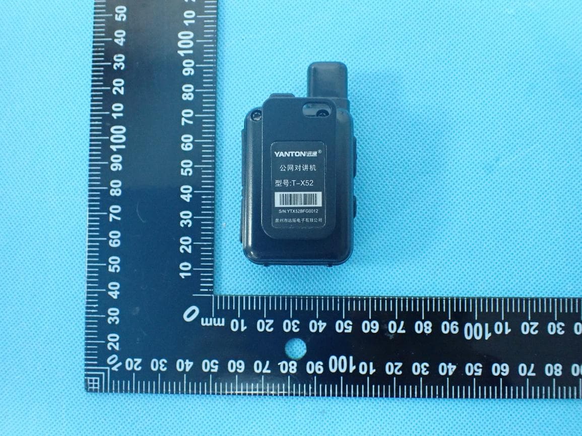
SV8-X5D
Jul 30, 2026SUPER MINI POC RADIO
Equipment Class
PCF - PCS Licensed Transmitter held to face
SV8-W53
Jun 05, 2026Two Way Radio
Equipment Class
FRE - Part 95 Family Radio Ear Held Transmitter
SV8-W7
Jan 26, 20264G POC Radio
Equipment Class
PCB - PCS Licensed Transmitter
SV8-T-S6
Jun 28, 2023TWO WAY RADIO
Equipment Class
FRF - Part 95 Family Radio Face Held Transmitter